
Summary of Contents for Microtronics EC-CAN-005
- Page 1 User manual EC-CAN-005 Cover Valid from: Firmware version: 01v030 Server version: 50v007 Hardware version: 1.4 301424 | Rev.09...
- Page 3 Chapter 1 Table of contents Chapter 1 Table of contents Cover Chapter 1 Table of contents Chapter 2 Declaration of conformity Chapter 3 Specifications Chapter 4 General specifications 4.1 Translation 4.2 Copyright 4.3 General descriptive names 4.4 Safety instructions 4.4.1 Use of the hazard warnings 4.4.2 General safety instructions 4.4.3 Safety and preventative measures for handling GSM/GPRS modems 4.4.3.1 Safety and precautionary measures for the GSM/GPRS modem installation...
- Page 4 6.3 Storage 6.4 Transport 6.5 Return Chapter 7 Installation 7.1 Dimensions 7.2 Installing the EC-CAN-005 7.2.1 Top-hat rail assembly 7.3 Safety instructions for the cabling 7.3.1 Information on preventing electrostatic discharges (ESD) 7.4 Electrical installation 7.4.1 Connecting the sensors, actuators and power supply 7.4.2 Connecting the GSM antenna...
- Page 5 8.2 Applicable documents 8.3 General principles 8.4 Commissioning the system 8.5 Testing communication with the device Chapter 9 User interfaces 9.1 User interface on the EC-CAN-005 9.1.1 Operating elements 9.1.1.1 Button 9.1.1.2 LED 9.2 User interface on the myDatanet server 9.2.1 Site configuration...
- Page 6 Chapter 11 rapidM2M Studio 11.1 General 11.2 Prerequisites 11.3 Project dashboard 11.4 CODEbed 11.5 TESTbed Chapter 12 Device Logic 12.1 General 12.1.1 Direct entry of a device logic 12.1.2 Uploading a binary file 12.1.3 Using the CODEbed of the web-based development environment rapidM2M Studio 12.2 rapidM2M Device API 12.2.1 Constants 12.2.2 Timer, date &...
- Page 7 Chapter 1 Table of contents 12.2.7 SPI, I2C, UART 12.2.7.1 Constants 12.2.7.2 Callback functions 12.2.7.3 Functions 12.2.8 Registry 12.2.8.1 Constants 12.2.8.2 Callback functions 12.2.8.3 Functions 12.2.9 Position 12.2.9.1 Arrays with symbolic indices 12.2.9.2 Constants 12.2.9.3 Functions 12.2.10 Math 12.2.11 Char & String 12.2.12 CRC &...
- Page 8 12.2.18 Brownout 12.2.18.1 Callback Funktionen 12.2.18.2 Funktionen 12.3 Device Logic error codes 12.4 Syntax 12.4.1 General syntax 12.4.1.1 Format 12.4.1.2 Optional semicolons 12.4.1.3 Comments 12.4.1.4 Identifier 12.4.1.5 Reserved keywords 12.4.1.6 Numerical constants 12.4.1.6.1 Numerical integer constants 12.4.1.6.2 Numerical floating-point constants 12.4.2 Variables 12.4.2.1 Declaration 12.4.2.2 Local declaration...
- Page 9 Chapter 1 Table of contents 12.4.5.5 Assignment 12.4.5.6 Comparative operators 12.4.5.7 Boolean 12.4.5.8 Other 12.4.5.9 Priority of the operators 12.4.6 Statements 12.4.6.1 Statement label 12.4.6.2 Composite statements 12.4.6.3 Expression statement 12.4.6.4 Empty statement 12.4.6.5 Assert expression 12.4.6.6 Break 12.4.6.7 Continue 12.4.6.8 Do statement while (expression) 12.4.6.9 Exit expression 12.4.6.10 For (expression 1;...
- Page 10 13.3 Special values of the data types Chapter 14 API 14.1 Backend API 14.2 rapidM2M Playground 14.2.1 Overview Chapter 15 Maintenance 15.1 General maintenance 15.2 Fuse replacement Chapter 16 Removal/disposal Chapter 17 Troubleshooting and repair 17.1 General problems 17.2 Log entries and error codes 17.2.1 Modem error 17.3 Evaluating the device log 17.3.1 Evaluating the device log on the myDatanet server...
-
Page 11: Chapter 2 Declaration Of Conformity
Chapter 2 Declaration of conformity Chapter 2 Declaration of conformity Rev. 09... -
Page 13: Chapter 3 Specifications
Chapter 3 Specifications Chapter 3 Specifications Voltage supply 24VDC (+5/-10%) Additional information is provided in "Technical details about the energy supply" on page Power typ. 0,5W consumption max. 3,5W Integrated Li-Po rechargeable battery with 900mAh for: buffer accu Reaction by application to power supply failure Disconnection from mobile network in the event of a power supply failure Additional information is provided in "Technical details about the energy management "... - Page 14 LTE FDD B1, B2, B3, B4, B5, B7, B8, B12, B13, B18, B19, B20, B26, B28 LTE TDD B38, B39, B40, B41 The EC-CAN-005 is equipped with an integrated SIM chip. MAIN and AUX as preparation for moduls of the category LTE CAT-1 and higher Possible failures or influences on the position determination due to existing 2.4 GHz W-LAN or 2-meter band radio.
-
Page 15: Chapter 4 General Specifications
4.4 Safety instructions For the connection, commissioning and operation of the EC-CAN-005 , the following information and higher legal regulations of the country (e.g. ÖVE), such as valid EX regulations as well as the applicable safety and accident prevention regulations for the respective application case must be observed. -
Page 16: Use Of The Hazard Warnings
4.4.1 Use of the hazard warnings DANGER: Indicates a potential or threatening hazardous situation that will result in death or serious injuries if not avoided. WARNING: Indicates a potential or threatening hazardous situation that can result in death or serious injuries if not avoided. - Page 17 Chapter 4 General specifications In addition to the following safety considerations, all directives of the country in which the device is installed must be complied with. Important note: No liability shall be assumed at any time and under no circumstances for connections via a GSM/GPRS modem for which wireless signals and networks are utilized.
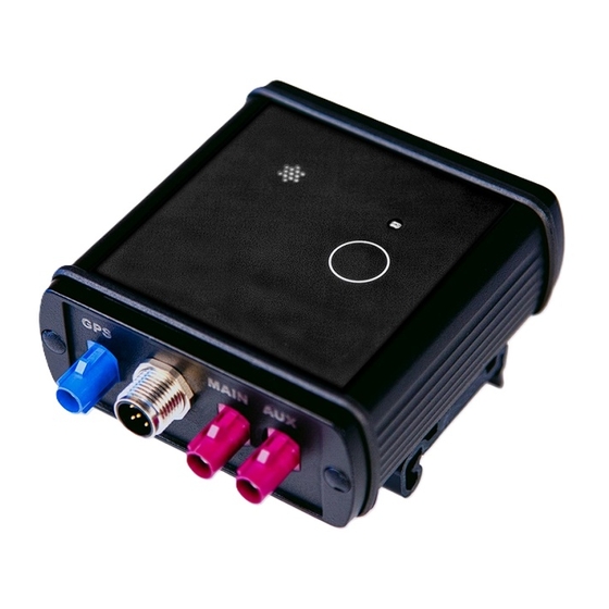
- Page 18 4.5 Overview Front of the EC-CAN-005 Rear of the EC-CAN-005 1 Pressure compensation 5 Connector for the supply and the CAN bus 2 LED 6 Connector for the primary mobile radio antenna (MAIN) 3 Button 7 Connector for the secondary mobile radio...
-
Page 19: Block Diagram
A Managed Service contract with Microtronics Engineering GmbH is required for use of the mobile data transmission (see www.microtronics.com/managedservice). This includes the provisioning of the mobile communications connection via the network of the service provider included in the above-mentioned list. -
Page 20: General Product Information
To acquire the data, there is a non-galvanically isolated CAN interface. It should be noted that the EC-CAN-005 is only suitable for systems with a continuous bus load of up to 40% . The EC-CAN-005 is also equipped with a multi-GNSS modul for an exact determination of the position. However, an external GNSS antenna is required to use this function. -
Page 21: Type Plates
The correct specification of the type designation and serial number is important for all queries and spare part orders. Only then can we process requests promptly and properly. Type plate EC-CAN-005 Note: This symbol indicates the country list profile (see www.microtronics.com/footprint) of the SIM chip installed in the device. 4.8.2 Packaging lables Packaging lable EC-CAN-005 Rev. -
Page 22: Installation Of Spare And Wear Parts
4.10 Storage of the product For safekeeping of the EC-CAN-005 , ensure that all relevant data was transferred to the myDatanet server. If necessary, initiate a transmission directly on the device using the solenoid contact (see "Button" on page 51), if you have included this in your Device Logic, and then check again to see whether all of the relevant data has now been transferred. -
Page 23: Obligation Of The Operator
For safety and warranty reasons, all internal work on the instruments beyond from that involved in normal installation and connection, must be carried out only by qualified Microtronics personnel or persons or companies authorised by Microtronics . -
Page 24: Personnel Requirements
4.14 Personnel requirements Installation, commissioning and maintenance may only be completed by personnel who meet the following conditions: Qualified specialist personnel with the relevant training Authorised by the facility operator Note: Qualified personnel In the context of these instructions and the warnings on the product itself, individuals responsible for the setup, installation, commissioning and operation of the product must have gained relevant qualifications relating to their activities, including, for example: Training, instruction and authorisation to activate/deactivate, ground and label electric circuits and... -
Page 25: Chapter 5 Functional Principle
Functional principle 1 EC-CAN-005 with integrated managed service SIM chip (including data transmission) 2 Application created by the customer (Device Logic) that collects and records the data (see "Device Logic" on page 71) - Page 26 The data blocks, on the other hand, are stored by the firmware of the EC-CAN-005 (see "rM2M_ RecData()"). The time of the synchronisation and the type of connection must also be determined by the application created by the customer.
-
Page 27: Recommended Procedure
393.216 Byte The internal data memory of the EC-CAN-005 is designed as a circular buffer with 8 sectors. If the entire memory (3MB ) is full, the sector with the oldest data is deleted fully before new data can be saved in this sector again. - Page 28 Note: Additional explanation regarding the functionality of the circular buffer Data memory after the first data is recorded: Data memory once 3MB has been recorded Data memory if further data is recorded once 3MB has already been recorded Note: Additional explanation on calculating the data volume to be saved: To provide a clear and simple overview, the following example assumes that the sectors can only record two complete data records.
-
Page 29: Memory Organisation
This memory block is only available if it was initialised via the "rM2M_RegInit()" function. The size of the binary must not exceed 256kB for the transmission to the EC-CAN-005 . If necessary, the data area of the binary can be compressed using a compiler instruction (#pragma amxcompress <0-3>). The binary (256kB ), 10 configuration blocks (4000 Bytes each), 4 registration memory blocks (1kB each) and measurement data (3MB ) are stored in the flash memory of the EC-CAN-005 . - Page 30 5.4 Procedure in case of connection aborts If the connection is terminated, another attempt to establish a connection is made after 2min. for all connections, except for "online" mode. Up to 2 attempts to establish a connection are made. Connection could be established during first retry. Connection could not be established despite 2 retries.
- Page 31 5.5 Timeout monitoring in online mode In online mode, the EC-CAN-005 sends a keep alive ping to the myDatanet server by default at an interval of 15 min. and 3 sec. (i.e. every 903 sec.). This enables the server to detect whether the connection to the EC- CAN-005 is still available.
-
Page 32: Error Handling
The "rM2M_GSMGetRSSI()" function can be used to read the last determined value from the system. 5.8 Determining the GSM position data An internal flag is set by the firmware every 24h , which ensures that the GSM position data is also determined the next time the "rM2M_TxStart()"... - Page 33 Chapter 5 Functional principle 5.10 Registration memory blocks In addition to 4 1kB blocks, that are saved in the flash, another one, that is saved in the RAM, can optionally be initialised via the "rM2M_RegInit()" function. Its size can be specified during initialisation, although it is limited to a maximum of 1kB .
-
Page 34: File Transfer
pipCtx Name of the site that should be created/used [2-50 characters]. pipAppId ID of the IoT application based on which the site should be created [max. 50 characters]. pipAppVer (optional) Version of the Device Logic currently installed on the device (e.g. 7) [Integer]. pipCtxAutocreate (optional) Indicates whether the site (if it does not exist yet) should be created ("0"... - Page 35 Chapter 5 Functional principle 5.12 Meaning of the SIM state The device receives information about the permissible use of the SIM chip from the myDatanet server. The following states are defined for this SIM status: Transmission via SIM state Explanation Device Logic RM2M_SIM_STATE_NONE Initial state...
-
Page 37: Chapter 6 Storage, Delivery And Transport
An RMA number is mandatory for any returns and can be obtained from the Support & Service Centre (see "Contact information" on page 225). The return shipment of the EC-CAN-005 must occur in the original packaging and with freight and insurance paid to Microtronics Engineering GmbH (see "Contact information"... -
Page 39: Chapter 7 Installation
7.1 Dimensions Dimensions: hight Dimensions: width and depth 7.2 Installing the EC-CAN-005 Important note: Ensure installation is completed correctly. Comply with existing legal and/or operational directives. Improper handling can cause injuries and/or damage to the devices. - Page 40 7.2.1 Top-hat rail assembly Top-hat rail assembly 1 EC-CAN-005 3 Top-hat rail 2 Assembly loop Important note: The EC-CAN-005 has to be mounted with the connection plugs pointing downwards. All other mounting positions are not permitted. Rev. 09...
-
Page 41: Safety Instructions For The Cabling
1. Place the assembly loop (2) on to the bottom edge of the top-hat rail. Turn slightly around the horizontal axis so that the EC-CAN-005 the assembly loop (2) clicks into the top-hat rail (see Abbildung "Top-hat rail assembly" on page 40). - Page 42 7.4.1 Connecting the sensors, actuators and power supply Important note: All wiring work must be performed in the de-energised state. Ensure installation is completed correctly. Comply with existing legal and/or operational directives. Improper handling can cause injuries and/or damage to the instruments. Run all data and power cables so that they do not pose a trip hazard and ensure that cables do not have any sharp bends.
-
Page 43: Connecting The Gsm Antenna
3. Cover all plugs that are not required with appropriate protective caps. Important note: All unused plugs of the EC-CAN-005 must be sealed watertightly using the protective caps included in the scope of delivery. Otherwise the degree of protection for the entire device is not guaranteed and the manufacturer's warranty is void. - Page 44 CAN interface are protected against overloading and are not damaged by a short circuit. It is possible to connect the EC-CAN-005 to the CAN bus at the end as well as via the branch lines. If the EC-CAN-005 is connected at the end of the bus instead of the prescribed 120Ω...
- Page 45 As soon as the external voltage supply available again, the EC-CAN-005 resumes operation according to the configuration and the charge controller ensures that the buffer battery is recharged. The charge controller is permanently active and works independently of firmware or device logic.
- Page 46 7.4.7 Technical details about the system time The EC-CAN-005 is equipped with a hardware real-time clock that has its own buffer battery with an expected service life of >10 years. The system time continues to run even if the power supply unit is removed.
-
Page 47: Chapter 8 Initial Start-Up
Study the manual thoroughly before placing into operation to prevent faulty or incorrect configuration. Utilise the manual to familiarise yourself with the operation of the EC-CAN-005 and the input screens of the myDatanet server before you begin with the configuration. - Page 48 4. Connect the antenna cables (see "Connecting the GSM antenna" on page 43). 5. Establish a connection so that the configuration of site is transferred to the EC-CAN-005 . If no script has been loaded in the device yet, this can be achieved by establishing the power supply (see "Connecting the sensors, actuators and power supply"...
-
Page 49: Testing Communication With The Device
With the exception of the "Online" connection type (see "rM2M_TxSetMode()"), the time during which the EC-CAN-005 is connected to the server is very short. It can therefore also be checked whether the time stamp of the last connection (under the green status symbol) has been updated. -
Page 51: Chapter 9 User Interfaces
2 Button 9.1.1.1 Button The button of the EC-CAN-005 is connected to the INT1 (X1-3 1-pin) of the inserted rapidM2M module. To use the button, both the interrupt has to be enabled using the rM2M_IrqInit() device logic function, and a callback fuction must be created to be called up by the system in the event on an interrupt. -
Page 52: Site Configuration
9.1.1.2 LED The LED of the EC-CAN-005 is connected to the GPIO1 (X1-23-pin) of the inserted rapidM2M module. The LED is controlled via the "rM2M_GpioSet()" device logic function. However, the signal direction of the GPIO1 has to be set to "Output" via the device logic function "rM2M_GpioDir()". - Page 53 Selection of the device logic binary file (*.amx) that is compiled script uploaded to the myDatanet server and is loaded into the EC-CAN-005 during the next connection. The file path is only displayed as long as the input screen for configuring the site has not been closed.
- Page 54 9.2.1.6 Basic settings Time zone Regional settings (not relevant for raw measurement data as this is stored in UTC) Daylight saving time Configuration for automatic time adjustment Standard The configuration for the time adjustment is adopted by the global server setting. Automatic time adjustment deactivated Predefined setting for the American area Predefined setting for the European area...
-
Page 55: Device Configuration
Chapter 9 User interfaces 9.2.2 Device configuration Note: Several of the configuration fields in the following sub chapters may possibly be hidden depending on the respective user level. In this case, contact the myDatanet server administrator. You can reach the input screen for configuring the device by clicking on the serial number in the site list (see "myDatanet Server Manual "... - Page 56 (malfunctions may occur). Identification String specifying the hardware platform implemented in the device and the corresponding hardware version (i.e. the rapidM2M module identification). Hardware version Hardware version of the EC-CAN-005 9.2.2.3 GPRS SIM tariff Selected SIM tariff...
-
Page 57: Explanation Of The Symbols
Chapter 10 myDatanet server Chapter 10 myDatanet server Note: All of the screenshots show version 50v007 of the myDatanet server using the standard colour scheme. Newer versions may include minor changes to the appearance of the server. 10.1 Overview Overview of the myDatanet server 1 Freely selectable logo 5 Opens the screen to input the global settings for the server... - Page 58 10.2 "Customer" area Overview of the "Customer" area 1 Area where an image file can be displayed as a "Map" and/or the OpenStreetMaps map can be displayed The sites can be manually placed on the image file used as a "map". In the OpenStreetMaps map, the sites are only displayed once GPS coordinates have been assigned to the site.
- Page 59 Chapter 10 myDatanet server 3 List of tags that are assigned to at least one of the customers displayed in the list of customers. If the list of customers was limited by the search field or selection of a tag, this is taken into consideration when creating the list of tags.
- Page 60 10.3 "Site" area at customer level Overview of the "Sites" area at customer level 1 Area where an image file can be displayed as a "Map" and/or the OpenStreetMaps map can be displayed The sites can be manually placed on the image file used as a "map". In the OpenStreetMaps map, the sites are only displayed once GPS coordinates have been assigned to the site.
-
Page 61: Map View
Chapter 10 myDatanet server 2 List of reports (see "Reports" on page 61) 3 List of sites/applications (see "Site" on page 52) 4 Symbol that represents a site on the "Map" 5 Symbol via which a OpenStreetMaps map, on which the sites are displayed, can be loaded. (see "Map view"... - Page 62 2. Click on the "Customer" menu item of the myDatanet server to call up the list of available customers. Select an existing customer or create a new customer. Selecting the customer 1 Menu item to call up the list of customers 3 List of available customers 2 Creating a new customer 3.
- Page 63 Chapter 10 myDatanet server 4. If necessary, change the suggested name of the site, select the desired site type or the desired application from the drop-down list and then click the "Add" button. Completing site creation 1 Name of the site (freely selectable) 3 "Add"...
- Page 65 11.1 General Access to the web-based development environment rapidM2M Studio is included in the Microtronics Partner Program, for which you can register free of charge at the following address: https://partner.microtronics.com...
- Page 66 11.2 Prerequisites Interfaces 1 x USB Operating system Windows 7 Windows 10 (recommended) MacOS 10.12 or higher Linux (Fedora 32, Ubuntu 20.04, Archlinux 2020.06.01) Internet Required connection Required disk No installation required space Browser Google Chrome only Rev. 09...
- Page 67 7 Tile that contains all important information about an IoT project 8 List of the "Collections" All projects that are not assigned to another "Collection" Favourite projects Sample libraries provided by Microtronics Samples provided by Microtronics "Collection" created by user 9 Button for creating a new "Collection"...
- Page 68 11.4 CODEbed CODEbed of the rapidM2M Studio 1 Navigation panel 2 Back to the project dashboard 3 Editor panel 4 Compiler results incl. warnings and errors 5 Memory usage 6 Context-sensitive help 7 Installs the current binaries of the project on the device and backend (i.e. on the myDatanet server) and opens the TESTbed Rev.
- Page 69 11.5 TESTbed TESTbed of the rapidM2M Studio 1 Debug console 2 First opens the window for selecting and connecting the "Device under test" and then the window for entering the access data for the "Backend under test" 3 Information on the "Device under test" 4 Watch panel 5 Information on the "Backend under test"...
- Page 71 The device logic is entered via the "Control" configuration section (see "Control" on page 53) of the input screen for configuring the site. "Pawn" must be selected as the "Device Logic Type" so that the EC-CAN-005 interprets the commands entered under "Device Logic" as a script.
- Page 72 12.2 rapidM2M Device API 12.2.1 Constants Return codes for general purposes = 0, ERROR = -1, ERROR_PARAM = -2, // Parameter error ERROR_UNKNOWN_HDL = -3, // Unknown handler, handle or resource error ERROR_ALREADY_SUBSCRIBED = -4, // Already subscribed service or resource error ERROR_NOT_SUBSCRIBED = -5, // Not subscribed service error...
- Page 73 Chapter 12 Device Logic 12.2.2 Timer, date & time 12.2.2.1 Arrays with symbolic indices TrM2M_DateTime Detailed breakdown of the date and time // year Year specified relates to the 21st century, i.e. 14 refers to the year 2014 // month Month (1..12) // day...
- Page 74 native rM2M_GetDate(&year=0, &month=0, &day=0, timestamp=0); If no time stamp was transferred (timestamp=0), the date (year, month, day) is determined for the current system time (in UTC). Alternatively, the date (year, month, day) is determined for the transferred time stamp. Parameter Explanation year Variable to store the year - OPTIONAL...
- Page 75 Chapter 12 Device Logic native rM2M_SetDateTime(datetime[TrM2M_DateTime], flags=0); Sets the system date and time to the values contained in the transferred structure Parameter Explanation datetime Structure that contains a detailed breakdown of the date and time (see "TrM2M_ DateTime" in chapter "Arrays with symbolic indices" on page 73). .timestamp = 0: The values contained in .year, .month, .day, .hour, .minute and .second are used to set the date/time.
- Page 76 native rM2M_TimerAdd(funcidx); Generates a new 1s timer Parameter Explanation funcidx Index of the public function that should be called up following expiry of the timer Type of function: public func(); Explanation Return value OK, if successful ERROR, If one of the following errors occurs: No valid index was transferred No further timers can be created (maximum number reached) In the event of an internal error...
- Page 77 Chapter 12 Device Logic native rM2M_TimerAddExt(funcidx, bool:cyclic, time); Generates a new ms timer Important note: The maximum number of simultaneously active ms timers is 8. Parameter Explanation funcidx Index of the public function that should be called up following expiry of the timer Type of function: public func();...
- Page 78 12.2.3 Uplink 12.2.3.1 Arrays with symbolic indices TrM2M_GSMInfo Information regarding the GSM modem, SIM chip and the GSM network used during the last connection // cgmi Manufacturer identification of the modem // cgmm Modem model information // cgmr Modem revision information // imei International mobile equipment identity of the modem // imsi...
- Page 79 Chapter 12 Device Logic 12.2.3.2 Constants SIM state //Connection can be initiated via devic logic RM2M_SIM_STATE_NONE = 0, //Initial state RM2M_SIM_STATE_PRODUCTION = 1, //Newly produced device is in stock RM2M_SIM_STATE_HOT = 2, //Valid contract //Connection cannot be initiated via device logic RM2M_SIM_STATE_COLD = 3, /*End of the contract or fair use policy...
- Page 80 Communication modes Communication modes for the rM2M_TxSetMode() function RM2M_TXMODE_TRIG = 0, // Interval RM2M_TXMODE_WAKEUP = 1, // Interval & wakeup RM2M_TXMODE_ONLINE = 2, // Online Communication mode flags Configuration flags for the rM2M_TxSetMode() function RM2M_TXMODE_SUPPRESS_SYNC = 0b00000001, /* no auto. sync. with the server when the connection type is changed */ Connection status Return values of the rM2M_TxGetStatus() function...
- Page 81 Chapter 12 Device Logic RM2M_TXERR_MODEM_SIM_NO_PIN, // pin code required but not available RM2M_TXERR_MODEM_EXTSIM_DENIED, /* external SIM not allowed (APN and/or feature key) */ RM2M_TXERR_MODEM_EXTSIM_MISSING, // external SIM not found RM2M_TXERR_MODEM_SIM_OTHER, /* any other problem with SIM card (e.g. internal SIM not found) */ // network-related error (GSM, GPRS, PDP, etc.) RM2M_TXERR_MODEM_NETWORK = 50, // unspecified network related error...
- Page 82 // network-related Ethernet errors RM2M_TXERR_ETH_NETWORK = 320, // unspecified network related Ethernet error RM2M_TXERR_ETH_NETWORK_TIMEOUT, // timeout accessing network RM2M_TXERR_ETH_DHCP_TIMEOUT, /* timeout receiving IP address from DHCP server */ // TCP-related Ethernet errors RM2M_TXERR_ETH_TCP = 340, // unspecified TCP related Ethernet error RM2M_TXERR_ETH_TCP_OPEN_TIMEOUT, // timeout opening TCP connection RM2M_TXERR_ETH_TCP_SEND_TIMEOUT,...
- Page 83 Chapter 12 Device Logic 12.2.3.3 Callback functions public func(const data[], len, timestamp, timestamp256); Function to be provided by the device logic developer, that is called up, once a data record has been read (using the function "rM2M_ReadData()" ) from the internal flash memory. Important note: The parameter "timestamp256"...
- Page 84 12.2.3.4 Functions native rM2M_TxStart(flags=0); triggers a connection to the server with subsequent synchronisation of all memory areas (measurement data, configuration, position data, device log, files,...) between the device and the server. Only those memory areas are transmitted whose content has been changed. If the device is in "online" mode and an active connection to the server is established then this function only triggers synchronisation.
- Page 85 Chapter 12 Device Logic native rM2M_TxSetMode(mode, flags=0); Sets the connection type to be used. If the connection type is changed to "Online" or "Interval & wakeup", this is immediately followed by a connection being established incl. a synchronisation with the server, as long as this is not suppressed by the "RM2M_TXMODE_SUPPRESS_SYNC"...
- Page 86 Note: Additional explanation about the connection types Connection type Energy consumption Data volumes Response time online Interval & wakeup Interval native rM2M_TxGetStatus(&errorcode=0); Returns the current connection status Parameter Explanation errorcode Variable to store the error code that occurred during the last connection attempt RM2M_TXERR_NONE: Last connection establishment successful >...
- Page 87 Chapter 12 Device Logic native rM2M_TxSelectItf(itf); Selects the communication interface to be used for the uplink Parameter Explanation Selection of the communication interface RM2M_TXITF_NONE: No uplink, communication with the server not possible RM2M_TXITF_MODEM: Mobile network modem RM2M_TXITF_WIFI: WiFi module RM2M_TXITF_LAN: LAN interface Explanation Return value...
- Page 88 native rM2M_GSMGetRSSI(flags=0); Returns the GSM/UMTS/LTE signal strength Important note: Although this function will still be supported for the purpose of downward compatibility, it should no longer be used for new projects. The "rM2M_GetRSSI()" function should be used as an alternative. Parameter Explanation flags...
- Page 89 Chapter 12 Device Logic native rM2M_GSMGetInfo(info[TrM2M_GSMInfo], len=sizeof info); Returns information on the GSM modem, SIM chip and the GSM network used during the last connection Parameter Explanation info Structure for storing the information (see "TrM2M_GSMInfo" in chapter "Arrays with symbolic indices" on page 78) Size (in cells) of the structure to store the information - OPTIONAL Explanation Return value...
- Page 90 native rM2M_RecData(timestamp, const data{}, len); Saves a data record in the internal flash memory. Use the "rM2M_Pack", "rM2M_SetPacked" or "rM2M_SetPackedB" functions to generate the data area. Parameter Explanation timestamp Time stamp that should be used for the recording = 0: The current system time is used as the time stamp. >...
- Page 91 Chapter 12 Device Logic native rM2M_CfgInit(cfg, flags); Sets the configuration for a configuration memory block. Calling the function is only necessary if one of the configuration flags should be set. Parameter Explanation Number of the configuration memory block starting with 0 for the first memory block.
- Page 92 native rM2M_CfgWrite(cfg, pos, const data{}, size); Saves the transferred data block at the specified position in a configuration memory block. Note that the configuration memory block is either saved in the RAM in a volatile manner (Bit0 = RM2M_CFG_ VOLATILE) or in the FLASH in a non-volatile manner (Bit0 = 0, default) depending on the type of storage selected via the "rM2M_CfgInit"...
- Page 93 Chapter 12 Device Logic native rM2M_CfgRead(cfg, pos, data{}, size); Reads a data block from the specified position in a configuration memory block. The function is also informed which of the 10 available memory blocks in the internal flash memory should be read. Use the "rM2M_Pack", "rM2M_GetPacked"...
- Page 94 = 1, // GPIO 1 GPIO_2 = 2, // GPIO 2 GPIO_3 = 3, // GPIO 3 GPIO_4 = 4, // GPIO 4 GPIO_5 = 5, // GPIO 5 //Number of GPIOs that the EC-CAN-005 has GPIO_NUM = 6, Rev. 09...
- Page 95 Chapter 12 Device Logic 12.2.4.3 Functions native Mx_GetSysValues(values[TMx_SysValue], len=sizeof values); Reads the last valid operating voltage values V and V from the system. The interval for determining these values is 1sec. and cannot be changed. Parameter Explanation values Structure for recording the measurement values (see "TMx_SysValue" in chapter "Arrays with symbolic indices"...
- Page 96 12.2.5 Encoding 12.2.5.1 Constants Configuration flags for the rM2M_Pack() function RM2M_PACK_GET = 0b00000001, // Value should be read (get packed) RM2M_PACK_BE = 0b00000010, // Use "Big endian" format RM2M_PACK_U8 = 0b00010000, // 8-bit unsigned RM2M_PACK_S8 = 0b10010000, // 8-bit signed RM2M_PACK_U16 = 0b00100000, // 16-bit unsigned RM2M_PACK_S16...
- Page 97 Chapter 12 Device Logic 12.2.5.2 Functions native rM2M_SetPacked(data{}, pos, &{Float,Fixed,_}:value, size=4, bool:bigendian=false); Writes the transferred value to a specified position in an array Important note: Although this function will still be supported for the purpose of downward compatibility, it should no longer be used for new projects as the signed data types might lead to problems.
- Page 98 native rM2M_SetPackedB(data{}, pos, const block{}, size); Writes the transferred data block to the specified position in an array Parameter Explanation data Array that should be used as a data area for a data record or a configuration Byte offset within the array to determine the position where the data block should be written block Data block that should be written in the array...
- Page 99 Chapter 12 Device Logic native rM2M_GetPacked(const data{}, pos, &{Float,Fixed,_}:value, size=4, bool:bigendian=false); Supplies the value that is located at the specified position in an array Important note: Although this function will still be supported for the purpose of downward compatibility, it should no longer be used for new projects as the signed data types might lead to problems.
- Page 100 native rM2M_GetPackedB(const data{}, pos, block{}, size); Reads a data block that is located at the specified position in an array Parameter Explanation data Array that should be used as a data area for a data record or a configuration Byte offset within the array to determine the position from which the data should be read block Array to store the data to be read...
- Page 101 Chapter 12 Device Logic native rM2M_Pack(const data{}, pos, &{Float,Fixed,_}:value, type); Function to access packed data. If the Bit0 (RM2M_PACK_GET) of the "type" parameter was set, the function returns the value that is located at the specified position in the array. Otherwise the function writes the transferred value to the specified position in the array.
- Page 102 12.2.6 GPIO, IRQ 12.2.6.1 Constants Signal direction settings of the GPIOs RM2M_GPIO_DISABLED = -1, /* Deactivate GPIO to minimise power consumption -) This turns off any input and output drivers -) If the device has level shifters, those shifters having all lines disabled become powered down, too.
- Page 103 Chapter 12 Device Logic 12.2.6.3 Functions native rM2M_GpioDir(gpio, dir); Sets the signal direction for a GPIO Parameter Explanation gpio Number of the GPIO, starting with 0 for the first GPIO of the device Signal direction to be used for the GPIO: RM2M_GPIO_DISABLED : GPIO deactivated RM2M_GPIO_INPUT : Input...
- Page 104 native rM2M_GpioGet(gpio); Reads the signal level of a GPIO that was configured as an input Parameter Explanation gpio Number of the GPIO, starting with 0 for the first GPIO of the device Explanation Return value RM2M_GPIO_LOW for "low" at the input RM2M_GPIO_HIGH for "high"...
- Page 105 Chapter 12 Device Logic native rM2M_IrqClose(irq); Deactivates the interrupt functionality of an interruptible pin. Parameter Explanation Number of the interruptible pin, starting with 0 for the first interruptible pin of the device Explanation Return value OK, if successful < OK, if an error occurs (see "Return codes for general purposes" in chapter "Constants"...
- Page 106 Configuration of the UART interface Configuration flags for the rM2M_UartInit() function RM2M_UART_1_STOPBIT = 0b000000001, // 1 stop bit RM2M_UART_2_STOPBIT = 0b0000000010, // 2 stop bits RM2M_UART_PARITY_NONE = 0b0000000000, // no parity RM2M_UART_PARITY_ODD = 0b0000000100, // odd parity RM2M_UART_PARITY_EVEN = 0b0000001000, // even parity RM2M_UART_7_DATABIT = 0b0000000000, // 7 data bits RM2M_UART_8_DATABIT...
- Page 107 Chapter 12 Device Logic 12.2.7.3 Functions native rM2M_SpiInit(spi, clock, config); Initialises the SPI interface Parameter Explanation Number of the SPI interface, starting with 0 for SPI1 clock Clock frequency in Hz to be used. Please observe the valid limits for the module being used (see ).
- Page 108 native rM2M_SpiClose(spi); Closes the SPI interface Parameter Explanation Number of the SPI interface, starting with 0 for SPI1 Explanation Return value OK, if successful ERROR, if the number of the SPI interface is invalid < OK, if another error occurs (see "Return codes for general purposes" in chapter "Constants"...
- Page 109 Chapter 12 Device Logic native rM2M_I2cInit(i2c, clock, config); Initialises the I C interface. Parameter Explanation Number of the I C interface, starting with 0 for I2C1 clock Clock frequency in Hz to be used. Please observe the valid limits for the module being used (see "Specifications"...
- Page 110 native rM2M_I2cCom(i2c, adr, data{}, txlen, rxlen); Executes an I C communication. Data is first of all sent and data is then received. Parameter Explanation Number of the I C interface, starting with 0 for I2C1 Address of the I C slave (Bit7-Bit1, Bit0 unused) data Array in which the data to be sent must initially be saved.
- Page 111 Chapter 12 Device Logic native rM2M_UartInit(uart, baudrate, mode, funcidx); Initialises the UART interface Parameter Explanation uart Number of the UART interface, starting with 0 for UART1 baudrate Baud rate to be used. Please observe the valid limits for the module being used (see "Specifications"...
- Page 112 Explanation Return value OK, if successful ERROR_NOT_SUPPORTED, if one of the pins required for the UART interface (e.g. RxD)is used elsewhere (e.g. as GPIO) ERROR, if an error occurs (see "Return codes for general purposes" in chapter "Constants" on page 72) native rM2M_UartSetbuf(uart, rxbuf{}, rxlen, txbuf{}, txlen);...
- Page 113 Chapter 12 Device Logic native rM2M_UartClose(uart); Closes the UART interface Parameter Explanation uart Number of the UART interface, starting with 0 for UART1 Explanation Return value OK, if successful < OK, if an error occurs (see "Return codes for general purposes" in chapter "Constants"...
- Page 114 12.2.8 Registry 12.2.8.1 Constants Indices of the registration memory blocks that can be accessed via the "rM2M_RegGetString()", "rM2M_RegGetValue()", "rM2M_ RegSetString()", "rM2M_RegSetValue()", "rM2M_RegDelValue()" and "rM2M_RegDelKey()" functions. Detailed information on the registration memory blocks is provided in chapter "Registration memory blocks" on page 33. //System-specific data RM2M_REG_SYS_OTP = 0, /* Written once as part of the production...
- Page 115 Chapter 12 Device Logic 12.2.8.2 Callback functions public func(reg); Function to be provided by the device logic developer, that is called up if the registration has changed Parameter Explanation Index of the registration memory block (see "Indices of the registration memory blocks"...
- Page 116 native rM2M_RegGetString(reg, const name[], string[], len=sizeof string); Reads a character string from a registration memory block. Detailed information on the registration memory blocks is provided in chapter "Registration memory blocks" on page 33. Parameter Explanation Index of the registration memory block (see "Indices of the registration memory blocks"...
- Page 117 Chapter 12 Device Logic native rM2M_RegSetString(reg, const name[], const string[]); Writes a character string into a registration memory block. Detailed information on the registration memory blocks is provided in chapter "Registration memory blocks" on page 33. Important note: This function accepts even characters which are fobidden according to JSON standard, such as ...
- Page 118 native rM2M_RegDelValue(reg, const name[]); Searches for an entry based on its name and sets the value of this entry (regardless of whether it is a string or value) to "null". Detailed information on the registration memory blocks is provided in chapter "Registration memory blocks"...
- Page 119 Chapter 12 Device Logic native rM2M_RegOnChg(funcidx); Specifies the function that should be called up if one of the registration memory blocks has changed (i.e. has been updated by the server). The callback is not triggered upon local (device-side) changes of a registration memory.Detailed information on the registration memory blocks is provided in chapter "Registration memory blocks"...
- Page 120 TrM2M_PosUpdateUMTS Information about a UMTS cell in the receiving range // type specifies the type of the entry (RM2M_POSUPDATE_TYPE_UMTS) // stamp Time when data was recorded // mcc MCC (Mobile Country Code) of the GSM cell // mnc MNC (Mobile Network Code) of the GSM cell // lac LAC (Location Area Code) of the GSM cell // cid...
- Page 121 Chapter 12 Device Logic 12.2.9.2 Constants List of the supported types of cell/network information entries Possible types of cell/network information entries that can be read from the system via the function "rM2M_EnumPosUpdate()" RM2M_POSUPDATE_TYPE_ERR = 0, //invalid entry RM2M_POSUPDATE_TYPE_GSM = 1, //Information about a GSM cell RM2M_POSUPDATE_TYPE_UMTS = 2, //Information about a UMTS cell RM2M_POSUPDATE_TYPE_LTE = 3, //Information about an LTE cell...
- Page 122 12.2.9.3 Functions native rM2M_SetPos(Lat, Long, Elev, Qual, SatUsed); Saves the GPS position information in the device. A historical record is not maintained. This means that the current position information always overwrites the last known position. The information is transmitted to the myDatanet server and can, for example, be read out via the API (see "API" on page 197).
- Page 123 Chapter 12 Device Logic native rM2M_DecodeNMEA(const sentence{}, data[], len=sizeof data); Decodes a transferred NMEA data record Parameter Explanation sentence NMEA data record from a GPS receiver starting with the '$' character. Important note: The strings must be terminated ('\0') immediately after the checksum.
- Page 124 native rM2M_SetPosNMEA(const Sentence{}); Takes the GPS position information from the transferred NMEA data record and saves it in the device. A historical record is not maintained. This means that the current position information always overwrites the last known position. The information is transmitted to the myDatanet server and can, for example, be read out via the API (see "API"...
- Page 125 Chapter 12 Device Logic native rM2M_GetPos(&Lat, &Long, &Elev, &Qual=0, &SatUsed=0); Reads out the GPS position information saved to the device Parameter Explanation Variable to store the geographical latitude in degrees (resolution: 0.000001°) -90 000 000 = South pole 90° south 0 = Equator +90 000 000 = North pole 90°...
- Page 126 native rM2M_EnumPosUpdate(...); lists the information saved in the device about the GSM/UMTS/LTE cells and WiFi networks in the receiving range. With this function a variable list of parameters is used. The parameters to be passed depend on the purpose. The following procedure is recommended: 1.
- Page 127 Chapter 12 Device Logic native rM2M_GetGSMPos(posidx, pos[TrM2M_GSMPos]=0); Returns the number of GSM/UMTS/LTE cells for which valid information is saved to the device (posidx < 0) or reads out the information saved to the device about a GSM/UMTS/LTE cell in the receiving range (posidx >= 0) Note: Use the "rM2M_EnumPosUpdate()"...
- Page 128 12.2.10 Math Helpful constants Definition Value Description 2.7182818284590452354 M_LOG2E 1.4426950408889634074 M_LOG10E 0.43429448190325182765 M_LN2 0.69314718055994530942 ln 2 M_LN10 2.30258509299404568402 ln 10 M_PI 3.14159265358979323846 π M_PI_2 1.57079632679489661923 π/2 M_PI_4 0.78539816339744830962 π/4 M_1_PI 0.31830988618379067154 1/π M_2_PI 0.63661977236758134308 2/π M_2_SQRTPI 1.12837916709551257390 2/sqrt(π) M_SQRT2 1.41421356237309504880 sqrt(2) M_SQRT1_2 0.70710678118654752440...
- Page 129 Chapter 12 Device Logic native max(value1, value2); Supplies the larger of the two transferred values Parameter Explanation value1 Two values of which the larger one is to be determined value1 Explanation Return value The larger of the two transferred values native clamp(value, min=cellmin, max=cellmax);...
- Page 130 native Float:asin(Float:x); Arcsine(x) in the range [-π/2, π/2], x element of [-1, 1] native Float:acos(Float:x); Arccosine(x) in the range [0, π], x element of [-1, 1] native Float:atan(Float:x); Arctangent(x) in the range [-π/2, π/2] native Float:atan2(Float:y, Float:x); Arctangent(y/x) in the range [-π, π] native Float:sinh(Float:x);...
- Page 131 Chapter 12 Device Logic 12.2.11 Char & String The mode of operation of the following functions essentially corresponds to that of the standard ANSI-C implementation: native strlen(const string[]); Returns the length of the string (without '\0') Parameter Explanation string Character string for which the length has to be determined Explanation Return value Number of characters without the final '\0'...
- Page 132 native sprintf(dest[], maxlength=sizeof dest, const format[], {Float,Fixed,_}:...); Saves the transferred format string in the array dest. The mode of operation of the functions corresponds to that of the "snprintf" function of the standard ANSI-C implementation. Note: If resulting string is longer than <dest>'s size, the very last character is set to terminating zero.
- Page 133 Chapter 12 Device Logic native strcat(dest[], const source[], maxlength=sizeof dest); Adds the source character string to the dest character string (including '\0') Important note: Both strings must be zero-terminated. Parameter Explanation dest Array to store the result. This array already contains one character string to which the source character string should be added.
- Page 134 native strrchr(const string[], char); Searches for a character (last occurrence) in a character string Parameter Explanation string Character string that should be searched char Character that the search is looking for Explanation Return value -1, if the character that the search is looking for is not included in the character string Array index for the character that the search is looking for (last character occurring in the character string)
- Page 135 Chapter 12 Device Logic native strpbrk(const string1[], const string2[]); Searches the array index of the first character that is also included in the character string of permitted characters Note: See similar function strcspn () which has a slightly different result. Parameter Explanation string1...
- Page 136 native strtol(const string[], base); Converts a character string into a value Note: Function differs slightly from it's C variant. Parsing consumes as many characters as possible, up to the first char not matching with given base. Parameter Explanation string Character string to be converted Important note: Strings >...
- Page 137 Chapter 12 Device Logic native memcpy_native(dst{}, const dstofs, const src{}, const srcofs, const bytes, const dst_ cells=sizeof dst, const src_cells=sizeof src); Copies bytes from one buffer to another one Parameter Explanation Target buffer to which the data should be copied dstofs Position (byte offset) in the target buffer to which the data should be copied Source buffer from which the data should be copied...
- Page 138 native memcmp_native(const src1{}, const src1ofs, const src2{}, const src2ofs, bytes, src1cells=sizeof src1, src2cells=sizeof src2); Compares two buffers, byte for byte Parameter Explanation src1 Buffer #1 src1ofs Position (byte offset) within buffer #1 from which the bytes should be compared src2 Buffer #2 src2ofs Position (byte offset) within buffer #2 from which the bytes should be compared...
- Page 139 Chapter 12 Device Logic 12.2.12 CRC & hash 12.2.12.1 Arrays with symbolic indices TMD5_Ctx Context structure for the MD5 calculation // init After being set to "0", the context structure can be used to calculate a new hash. If a calculation should be implemented by calling up the "MD5"...
- Page 140 native MD5(data{}, len, hash{16}, ctx[TMD5_Ctx] = [0]); Calculates the MD5 hash for the transferred data. If the hash for a data block should be calculated by calling up this function several times (e.g. when receiving data in blocks), then the same context structure must be transferred every time the function is called up.
- Page 141 Chapter 12 Device Logic TrM2M_Id Information for identifying the module/device // string rapidM2M module identification (e.g. "rapidM2M M2 HW1.3") // module rapidM2M module type (e.g. "M2") // hwmajor Hardware: Major version number // hwminor Hardware: Minor version number // sn Device serial number (binary) in BIG endian format E.g.: "010146AF251CED1C"...
- Page 142 native exists(const name[]); checks whether the required rapidM2M API function is supported by the device firmware Important note: Use getapilevel () upfront to check if exists() is avilable with your firmware version. Parameter Explanation name Name of the required rapidM2M API function Explanation Return value true, if the function is available...
- Page 143 Chapter 12 Device Logic native rtm_stop(measurement[TRTM_Data]); Stops the runtime measurement and calculates the time in [ms] since the "rtm_start()" function was called up and the instructions executed since then. The determined values are written in the ".runtime" and ".instructions" elements of the transferred structure to record the information regarding a runtime measurement.
- Page 144 native CalcTable(key, &value, const table[][TablePoint], size = sizeof table); Searches for a certain value in the "key" column of the transferred reference point table and supplies the relevant value from the "value" column in the table. If the searched value is between two reference points, the returned value is interpolated linearly between the two adjacent values in the "value"...
- Page 145 Chapter 12 Device Logic native rM2M_GetId(id[TrM2M_Id], len=sizeof id); Provides the information to identify the module/device Parameter Explanation Structure for storing the information to identify the module/device (see "TrM2M_ Id" in chapter "Arrays with symbolic indices" on page 140) Size (in cells) of the structure to store the information - OPTIONAL Explanation Return value Used size (in cells) of the structure for storing the information...
- Page 146 native getarg(arg, index=0); This function supplies an argument from a variable argument list. If the argument is an array, the "index" specifies the index of the required array element. Parameter Explanation The sequence number of the argument. Use 0 for the first argument. index Index if "arg"...
- Page 147 Chapter 12 Device Logic native delay_us(us); Blocking delay function. The execution of the device logic is stopped and the following code line is only executed once the delay time has expired. Parameter Explanation Delay time (1...10000 [µs]). Explanation Return value OK, if successful ERROR, if an error occurs 12.2.14 Console...
- Page 148 native printf(const format[], {Float,Fixed,_}:...); Prints the transferred format string to the standard output. The mode of operation of the functions corresponds to that of the standard ANSI-C implementation. Note: Characters may get lost if console output buffer overflows. Use sprintf () to write to a string buffer instead of the console. Parameter Explanation format[]...
- Page 149 Chapter 12 Device Logic 12.2.15 SMS Important note: If the device is in "online" mode no SMS can be processed. 12.2.15.1 Callback functions public func(const SmsTel[], const SmsText[]); Function to be provided by the device logic developer, that is called up if an SMS is received Parameter Explanation SmsTel...
- Page 150 12.2.16 File transfer 12.2.16.1 Arrays with symbolic indices TFT_Info Properties of a file entry // name Name of the file // stamp Time stamp of the file (seconds since 31.12.1999) // stamp256 Fraction of the next started sec. (resolution 1/256 sec.) // size File size in byte // crc...
- Page 151 Chapter 12 Device Logic Parameter Explanation Unique identification with which the file is referenced (specified during registration) File transfer command that was received from the system and that has to be processed by the callback function data This parameter is only relevant when the following file transfer commands are received: FT_CMD_STORE: Array that contains the properties of the file that should be newly created.
- Page 152 12.2.16.4 Functions native FT_Register(const name{}, id, funcidx); Registers a file made available by the device logic. Parameter Explanation name Unique file name Unique identification with which the file is subsequently referenced (freely selectable) funcidx Index of the public function that should be called up if a file transfer command has been received Type of function: public func(id, cmd, const data{}, len, ofs);...
- Page 153 Chapter 12 Device Logic native FT_RegisterEnum(id, funcidx, props[TFT_Info], len=sizeof props); Registers a file node made available by the device logic. Several files can be managed via a file node. Parameter Explanation Unique identification with which the file node is subsequently referenced (freely selectable) funcidx Index of the public function that should be called up if a file transfer command has...
- Page 154 native FT_SetProps(id, stamp, size, crc, flags); Sets the properties of a file Important note: This function must be called up following receipt of a "FT_CMD_LIST" command. Important note: Although this function will still be supported for the purpose of downward compatibility, it should no longer be used for new projects.
- Page 155 Chapter 12 Device Logic native FT_Read(id, const data{}, len); Transmits the data to the system, to transfer it to the myDatanet server. The data must be provided by the callback function specified via "FT_Register()". Important note: This function must be called up following receipt of a "FT_CMD_READ" command.
- Page 156 native FT_Written(id, len); Confirms that the data received from the myDatanet server has been written. The actual writing process must be executed via the callback function specified via "FT_Register()". The data that is to be written is transmitted to the callback function by the system (see "Callback functions" on page 150). Important note: This function must be called up following receipt of a "FT_CMD_WRITE"...
- Page 157 Chapter 12 Device Logic 12.2.17.2 Functions native MxLed_Init(mode); Initialises the open drain output to which an LED can be connected Parameter Explanation mode Selection of whether the output is controlled by the firmware or device logic MX_LED_MODE_ The output is used to indicate the operating state (see INTERNAL : "LED"...
- Page 158 native MxLed_Off(bool:green); Sets the open drain output to "high", which triggers an LED connected between the supply and output to switch off Parameter Explanation green true: The LED is switched off. Explanation Return value OK, if successful ERROR, if an invalid parameter was transferred native MxLed_Blink(green);...
- Page 159 Chapter 12 Device Logic native MxLed_Flicker(green); Enables an LED connected to the open drain output to flicker (t = 94ms , t = 31ms ). Parameter Explanation green -1 : The LED remains switched off. 0 : The LED flickers until it is deliberately switched off. >0 : Number of times the LED should flicker Explanation Return value...
- Page 160 12.2.18 Brownout 12.2.18.1 Callback Funktionen public func(level); Function to be provided by the device logic developer, that is called up when a BrownOut is detected on the supply voltage input V Parameter Explanation level Voltage level in [mV] that caused the BrownOut to be detected 12.2.18.2 Funktionen native Mx_BrownOutInit(funcidx, level);...
- Page 161 Chapter 12 Device Logic Log entry Parameter Description Code Plain text Code Plain text 3000 SCRIPT_ERR NO SCRIPT No valid Device Logic available SCRIPT UPDATE New Device Logic received SCRIPT EXCEPT Exception loop detected (4 system starts due to LOOP exception within 10 min.).
- Page 162 Log entry Parameter Description Code Plain text Code Plain text 3002 AMX_ERR_ Assertion failed ASSERT 3003 AMX_ERR_ Stack/heap collision (insufficient stack size) STACKERR 3004 AMX_ERR_ Array index outside the valid range BOUNDS 3005 AMX_ERR_ Invalid memory access MEMACCESS e.g. mix-up between cell (32-bit element) access [] and byte access {} 3006 AMX_ERR_ Invalid statement...
- Page 163 Chapter 12 Device Logic Log entry Parameter Description Code Plain text Code Plain text 3024 AMX_ERR_INIT_ JIT cannot be initialised. 3025 AMX_ERR_ Faulty parameter PARAMS 3026 AMX_ERR_ Domain error. The result of the expression is not DOMAIN in the valid range. 3027 AMX_ERR_ General error (invalid or non-specific error) GENERAL...
-
Page 164: General Syntax
12.4 Syntax 12.4.1 General syntax 12.4.1.1 Format Identifiers, numbers and characters are separated by spaces, tabs, line breaks and "form feed". A series of one or more of these separators is recognised as an empty space. 12.4.1.2 Optional semicolons Semicolons (used to finish a statement) are optional if they are at the end of a line. Semicolons are required to separate several statements in a line. - Page 165 Chapter 12 Device Logic 12.4.1.6 Numerical constants 12.4.1.6.1 Numerical integer constants Binary 0b followed by a series of 0 and 1 Decimal A series of numbers between 0 and 9 Hexadecimal 0x followed by a series of numbers between 0 and 9 and the letters a to f 12.4.1.6.2 Numerical floating-point constants A floating-point number is a number with numbers after the decimal point.
-
Page 166: Array Variables
12.4.2.4 Static local declaration A local variable is destroyed if the execution leaves the block in which the variable was created. Local variables in a function only exist during the operating time of the specified function. Each new call up of the function creates and initialises new local variables. - Page 167 Chapter 12 Device Logic 12.4.4.2 Initialisation Data objects can be initialised during their declaration. The initialised value from global data objects must be a constant value. Global or local arrays must also be initialised with constant values. Data that is not initialised are zero by default.
- Page 168 new e[2][] = [ ’’OK’’, ’’Cancel’’ ] new f[][] = [ ’’OK’’, ’’Cancel’’ ] As the last two declarations (variables "e" and "f") illustrates, the last dimension has an unspecified length. In this case, the length of the sub-array is detected by the associated initialiser. Each sub-array is a different length.
- Page 169 Chapter 12 Device Logic 12.4.5 Operators and expressions 12.4.5.1 Notational conventions The use of some operators is dependent on the relevant type of operand. The following notations are therefore used in this chapter: Any expression Any expression that can be assigned a value ("lvalue" expression - variable) An array A function A symbol - this can be a variable, a constant or a function...
- Page 170 12.4.5.4 Bit manipulation Operator Example Explanation The result is the one's complement of e. >> e1 >> e2 The result of the arithmetic shift to the right of e1 by e2 bits. The shift is signed: The bit on the far left is copied to the free bits of the result. >>>...
- Page 171 Chapter 12 Device Logic 12.4.5.6 Comparative operators A logical "false" is represented by an integer value of 0; a logical "true" is represented by a value that is not 0. Results of a comparative expression are either 0 or 1 and the "tag" is set to "bool". Operator Example Explanation e1 == e2 The result is "true"...
- Page 172 12.4.5.8 Other Operator Example Explanation a[e] Array index: The result is the entry at position e of array a. a{e} Array index: The result is the index at position e of "packed" array a: f(e1, e2, ... eN) The result is the value that is returned by function f. The function is called up with parameters e1, e2, ...
- Page 173 Chapter 12 Device Logic Operator Explanation Reading order Function call left-to-right array index (element) array index (character) logical not right-to-left one's complement two's complement (unary minus) increase decrease "tag" overwritten defined symbol definition status sizeof symbol size in "elements" tagof unique number of the tag multiplication left-to-right...
- Page 174 Each statement can be marked with a label. The label must be followed by a statement, which can also be an "empty statement". The scope of a label is the function in which it was declared, i.e. a "goto" statement cannot jump from the current function to another function.
- Page 175 Chapter 12 Device Logic 12.4.6.6 Break Terminates and leaves the smallest, encircling "do", "for" or "while" statement at any point in the loop. The "break" statement moves the program flow to the next statement outside the loop. Example: example(n) new a = 0 for(new i = 0;...
- Page 176 12.4.6.8 Do statement while (expression) Executes a statement before the conditional part (the "while" condition) is evaluated. The statement is repeated as long as the condition is logical "true". The statement is executed at least once. Example: example(n) new a = 0 while(n >= 0) return a 12.4.6.9 Exit expression...
- Page 177 Chapter 12 Device Logic Example: example(n) new a = 0 for(new i = 0; i < n; i++) return a The "for ( ; ; )" statement is the same as the "while (true)" statement. 12.4.6.11 Goto label Moves the program control (unconditionally) to the statement that follows the specified label. The label must be within the same function as the "goto"-statement (a "goto"-statement cannot jump out of a function).
- Page 178 The "switch" statement shifts the sequence control to a "case" clause if a value from the list corresponds to the value of the "switch" expression. The "default" clause consists of the "default" keyword and a double point. The "default" clause is optional, however, if it is specified it must be included as the last entry in the "case"...
- Page 179 Chapter 12 Device Logic 12.4.7 Functions A function declaration specifies the name of the function and the formal parameters enclosed in brackets. A function can also return a value. A function must be defined globally, i.e. declared outside of another function and is globally available.
- Page 180 main() new v = 5 new f = faculty(v) faculty(n) assert n >= 0 new result = 1 while (n > 0) result *= n-- return result Regardless of what (positive) value the "n" variable has at the start of the "while" loop, "n" will equal zero at the end of the function.
- Page 181 Chapter 12 Device Logic The following code example calls up the "addvector" function and adds five to each element of the "vect" variables: new vect[3] = [ 1, 2, 3 ] addvector(vect, [5, 5, 5], 3) /* vect[] now comprises the values 6, 7 and 8 */ 12.4.7.2 Named parameters versus fixed parameters In the previous examples, the order of the parameters in a function call were important as each parameter was copied to the same position of the function parameter.
- Page 182 For example, if the "increment" function is defined as follows: increment(&value, incr=1) value += incr The following function calls are all the same: increment(a) increment(a, _) increment(a, 1) Standard values for arguments that are transferred as a reference are helpful in making these parameters optional.
- Page 183 Chapter 12 Device Logic "pointers" are not supported. A "reference" argument to transfer function parameters as a reference (see "Function arguments ("call-by-value" versus "call-by-reference")" on page 179) is included.. The "placeholder" argument replaces some applications of the ZERO pointer (see "Standard values of function arguments"...
- Page 184 In most cases, the forward declarations of functions (i.e. prototypes) are not necessary as a two-pass compiler is used. It detects all of the functions during the first cycle and uses them during the second. User-defined operators must however be declared before use. If available, forward declarations must be exactly the same as the definition of the function.
-
Page 185: Data Structure
The basic principle of the EC-CAN-005 is "storage-2-storage" data transmission. For this type of data transmission, neither the EC-CAN-005 nor the server must know about the logical content of the data blocks. Therefore, the only aim is to transport a block of data from A to B. - Page 186 13.1.1 Division of a structured measurement data channel into individual data fields #histdata0 Measurements up BatVoltage s16 title="Battery Voltage" decpl=2 units="V" vscale=0.001 InputVoltage s16 title="USB Voltage" decpl=2 units="V" vscale=0.001 The first line in the example above specifies the container to be used for the measurement data: #histdata0: The measurement data should be stored in histdata channel 0. Measurements: "Measurements"...
- Page 187 13.1.2 Division of a configuration memory block into individual data fields #config0 BasicCfg down title="Basic configuration" RecordItv u32 title="Record Interval" units="sec" min=10 default=10 TransmissionItv u32 title="Transmission Interval" units="min" min=10 default=60 The first line in the example above specifies the container to be used for the configuration: #config0: The parameters should be stored in configuration memory block 0. BasicCfg: "BasicCfg"...
- Page 188 13.1.3 Division of the aloha data into individual data fields #aloha up BatVoltage s16 title="Battery Voltage" decpl=2 units="V" vscale=0.001 InputVoltage s16 title="USB Voltage" decpl=2 units="V" vscale=0.001 The first line in the example above specifies the container to be used for the aloha data: #aloha: The measurement data should be stored in the aloha data container. The data is only transmitted from the device to the server.
- Page 189 editmask Format statements for displaying the field content on the interface of the myDatanet server or input via the interface of the myDatanet server. usable for strings (data type "astr", "nstr", "wstr" and "ustr", however not for "cstr") Format statements Explanation "%COLORPICKER%"...
- Page 190 usable for numeric fields (data type "u8", "s8", "f32", ..) Format statements Explanation "%2.x0" Creates an input field in which the numeric value is displayed in hex format. Each byte of the data type is therefore represented by two characters. The number after "%" must match the number of characters required to represent the data type (e.g.
- Page 191 usable for timestamps (data type "stamp32" and "stamp40") Format statements Explanation %DATETIMEPICKER% Creates an input field in which the timestamp is displayed as date/time. When clicking on the input field, a dialog field to select date and time appears. decpl Numeral, integer positive.
- Page 192 view Numeral, integer positive. Specifies from which user level, the field is visible on the interface of the myDatanet server. edit Numeral, integer positive. Specifies the user level that is required to be able to change the field content via the interface of the myDatanet server. If this attribute is not specified or if the specified value is lower than that of the "view"...
- Page 193 13.2 Example #histdata0 Measurements up Delay title="Delay" units="sec" min=10 max=2000 vofs=10 chmode=3 index=1 Height f32 title="Height" decpl=2 units="cm" min=0 max=2000 vscale=0.01 chmode=6 index=0 Pump view=99 edit=99 @Pump Pump_MSK dlorw=skip title="Pump" bitmask=$01 min=0 max=1 chmode=1 Info astr.50 title="Info" index=10 The first line specifies the container to be used for the measurement data: #histdata0: The measurement data should be stored in histdata channel 0. Measurements: "Measurements"...
- Page 194 max: Maximum value for the further display on the server (e.g. graphic) vscale: Virtual scaling of the value (see "Attributes of the field definition" on page 188). In the current example the extracted value is multiplied by 0.01. chmode: Channel mode 6 =^ analogue channel (a "simple"...
- Page 195 The 7th line describes the fourth measurement value "Info" in the measurement data container used: Info: "Info" should be used as the name for the measurement value. astr.50: The data type used for the measurement value should be an ANSI string. After the dot the number of characters (50 in the current example) are specified.
- Page 197 Chapter 14 API Chapter 14 API Important note: The relevant licences are required on the myDatanet server to use the API (Application Programming Interface). For future information contact your responsible sales partner. 14.1 Backend API The API is provided to export data from and import data to the myDatanet server. However, this is not just limited to the pure measurement data but includes all of the data provided by myDatanet server (e.g.
- Page 198 14.2.1 Overview rapidM2M Playground 1 Input field for the user name 2 Input field for the password 3 List of the available HTTP commands. The HTTP commands are grouped according to their fields of application. 4 Depending on the selected HTTP command, the drop down lists for selecting the customer, user and site that should replace the corresponding wild cards ("$CID"...customer , "$UID"...user, "$SID"...site) in the resource path of the HTTP command are displayed.
-
Page 199: Chapter 15 Maintenance
Check all of the connections for leaks or corrosion on a regular basis. Check all of the cables for mechanical damage at regular intervals. Clean the EC-CAN-005 with a soft, moist cloth. Use a mild cleaning agent, if necessary. 15.2 Fuse replacement DANGER: Risk of fire. -
Page 201: Chapter 16 Removal/Disposal
Logo of the EU WEEE Directive This symbol indicates that the requirements of Directive 2012/19/EU regarding the scrap disposal of waste from electric and electronic equipment must be observed. Microtronics Engineering GmbHsupports and promotes recycling and environmentally friendly, separate collection/disposal of waste from electric and electronic equipment in order to protect the environment and human health. -
Page 203: Chapter 17 Troubleshooting And Repair
Check the T2A pre-fuse (see "Block diagram" on page 19). Communication Load the device log using the DeviceConfig of the EC-CAN-005 (see "Evaluating problems the device log using DeviceConfig " on page 211). A list of all the possible error codes is included in the chapter "Log entries and error codes"... -
Page 204: Log Entries And Error Codes
17.2 Log entries and error codes Log entry Parameter Description Code Plain text Code Plain text 1000 POWER ON Restart following a power failure Watchdog reset (e.g. because of an exception) Reset was initiated by the device itself (e.g. in event of firmware update) Restart for another reason. - Page 205 Chapter 17 Troubleshooting and repair Log entry Parameter Description Code Plain text Code Plain text 1039 UV MODEM The rechargeable battery or battery voltage once RECOVER again suffices to guarantee a stable connection. This is either achieved by replacing the rechargeable battery or battery pack or by ensuring that the charge control has charged the battery sufficiently.
- Page 206 Log entry Parameter Description Code Plain text Code Plain text 1208 GPRS NETWORK NOT REGISTERED Not registered, modem is currently not looking REGISTRATION for any new operators to register HOME Registered, home network SEARCHING Not registered, but the modem is currently looking for a new operator with which it can register DENIED...
- Page 207 Chapter 17 Troubleshooting and repair Log entry Parameter Description Code Plain text Code Plain text 1335 LOG_SHT2X_ SHT2X SENSOR The internal temperature and air humidity sensor STATE is returning valid values again SHT2X RH ERROR A communication error occured when reading the air humidity value from the internal temperature and air humidity sensor.
- Page 208 Log entry Parameter Description Code Plain text Code Plain text 1910 ACCU 0 E2PROM Rechargeable battery not available ERROR Invalid length of the data structure in the EEPROM of the rechargeable battery No charging profile available in the EEPROM (only with Li-ion rechargeable batteries) Error when reading the SoC-value Error when writing the SoC-value The charging profiles of the rechargeable...
-
Page 209: Modem Error
FAILED Try to improve the position of the antenna. Check whether the device is in the coverage area (www.microtronics.com/footprint). 1200 BAND SEL FAILED -969 --- A network could not be found on the GSM900/1800 or on the GSM850/1900 band. Try to improve the position of the antenna. -
Page 210: Evaluating The Device Log
1200 NETLOCK ERROR -966 Error when selecting the network. Check whether the device is in the coverage area. Internal SIM chip: see www.microtronics.com/footprint TCP channel error 1200 CHANNEL -965 --- An attempt is being made to write to/read a TCP ABORTED client that is no longer available. - Page 211 The DeviceConfig program can be used to read all of the stored log entries, including those that have not yet been transferred to the myDatanet server, directly from the EC-CAN-005 via the USB interface. Rev. 09...
-
Page 213: Chapter 18 Document History
Chapter 18 Document history Chapter 18 Document history Rev. Date Changes 15.09.2017 First version 16.10.2017 Chapter "Block diagram" on page 19 The pre-fuse implemented by the user has been added to the diagram. Chapter "Connecting the sensors, actuators and power supply" on page 42 Note added indicating that the supply line must be secured by the user using a pre- fuse Chapter "Fuse replacement"... - Page 214 Chapter "File transfer" on page 34 Specification of the maximum number of files that can be registered for file transfer added Chapter "Installing the EC-CAN-005 " on page 39 Note added indicating that the pressure compensation must be protected against contamination Chapter "Technical details about the system time"...
- Page 215 Chapter 18 Document history Rev. Date Changes 14.06.2019 Chapter "Uplink" on page 78 Explanation supplemented in such a way to indicate that the connection in online (2/3) (2/3) mode is interrupted every seven days to check the server assignment Explanation of the "errorcode" parameter of the "rM2M_TxGetStatus()" function added Explanation of the constants for the connection error codes added Explanation of the "RM2M_TX_SUPPRESS_POSUPDATE"...
- Page 216 Chapter "Technical Compliance Statement FCC" Chapter added Chapter "Declaration of conformity" on page 11 Variants EC-CAN-001and EC-CAN-002 removed Variant EC-CAN-005 added Chapter "Specifications" on page 13 Specified system-related overheads per data record adjusted from 10 bytes to 11 bytes Specified max. size of a data record adjusted from 1024 bytes to 1023 bytes...
- Page 217 Chapter "Technical details about the USB interface" on page 45 The rapidM2M Toolset has been replaced by the web-based develompment environment rapidM2M Studio . Link for free registration to the Microtronics Partner programme added. Chapter "Applicable documents " on page 47 Chapter added...
- Page 218 Rev. Date Changes 31.01.2023 Chapter "Commissioning the system" on page 47 Explanation adapted to version 50v007 of the myDatanet server (3/6) (3/6) Chapter "Testing communication with the device" on page 49 Explanation adapted to version 50v007 of the myDatanet server Chapter "Site"...
- Page 219 Chapter 18 Document history Rev. Date Changes 31.01.2023 Chapter "Uplink" on page 78 Explanation of the arrays with symbolic indices "TrM2M_GSMInfo" extended to (4/6) (4/6) include the description of the "act", "lac" and "cid" elements Explanation of the array with symbolic indices "TrM2M_TxItfStats" added Explanation of the constants for the mobile radio AcT (access technology) added Explanation of the constants for the signal strength measurement flags added Explanation of the function, that must be provided by the device logic developer and...
- Page 220 Rev. Date Changes 31.01.2023 Chapter "Char & String" on page 131 Note added to the "strchr", "strrchr", "strspn", "strcspn" , "strpbrk" , "strstr" , "strtol" (5/6) (5/6) and "atof" functions indicating that strings > 128 bytes are not supported Explanation of the "memcpy_native", "memset_native" and "memcomp_native" functions added Explanations of the "sprintf()", "strcat()", "strcmp()", "strcspn()", "strpbrk()", "strstr()", "strtol()"...
- Page 221 Chapter 18 Document history Rev. Date Changes 31.01.2023 Chapter "Evaluating the device log using DeviceConfig " on page 211 Chapter added (6/6) (6/6) Chapter "Log entries and error codes" on page 204 Explanation of the error codes "GSM NETWORK REGISTRATION", "GPRS NETWORK REGISTRATION"...
-
Page 223: Chapter 19 Glossary
The manufacturer's devices are equipped with subscriber identity modules (SIM) ex-works for the purpose of mobile data transmission. The footprint describes those countries and regions where a mobile connection is available (see www.microtronics.com/footprint). Device logic The device logic is the intelligence installed on the device that determines the local functionality of the device. - Page 224 rapidM2M Store Is responsible for distributing the app models to the individual myDatanet servers. When installing and updating IoT apps the myDatanet server access the app models provided in the rapidM2M Store . The developer of the respective app model defines which myDatanet servers are allowed to access an app model via the rapidM2M Studio .
-
Page 225: Chapter 20 Contact Information
Chapter 20 Contact information Chapter 20 Contact information Support & Service: Microtronics Engineering GmbH Hauptstrasse 7 3244 Ruprechtshofen Austria, Europe Tel. +43 (0)2756 7718023 support@microtronics.com www.microtronics.com Microtronics Engineering GmbH (Headquarters) Hauptstrasse 7 3244 Ruprechtshofen Austria, Europe Tel. +43 (0)2756 77180 Fax. - Page 226 Certified by TÜV AUSTRIA: EN ISO 9001:2015, EN ISO 14001:2015, ISO/IEC 27001:2013, EN ISO 50001:2011 for myDatanet | TÜV SÜD: ATEX Directive 2014/34/EU © Microtronics Engineering GmbH. All rights reserved. Photos: Microtronics, shutterstock.com Microtronics Engineering GmbH | www.microtronics.com Hauptstrasse 7 | 3244 Ruprechtshofen | Austria | +43 2756 77180 | office@microtronics.com 301424 | Rev.09...
Need help?
Do you have a question about the EC-CAN-005 and is the answer not in the manual?
Questions and answers