
Summary of Contents for Alpha Communications GSM4INTLTE-2
- Page 1 Installation & Operations Manual 4G Cellular Gateway GSM4INTLTE-2 42 Central Drive - Farmingdale NY 11735 AWD302 Rev 05/23 www.alphacommunications.com...
-
Page 2: Table Of Contents
Table of Contents Items Needed ....... . Page 3 Setting up the Cellular Gateway ....Page 3 Connector Description . -
Page 3: Items Needed
Items Needed Included: • 4G Cellular Gateway • Antenna • 2-year prepaid SIM card and plan (AT&T or Verizon) Note: We recommend utilizing the provided antenna. If the signal is not strong enough in the intended installation location, we suggest moving the unit to a location with a stronger signal. If this is not feasible, you can try installing signal boosters to amplify the cellular signal throughout the building. - Page 4 5. Connect the phone(s). The Cellular Gateway provides an RJ11 jack or hardwired screw terminals for Do not exceed 1,000 feet. connecting devices. RJ11 Jack: a. Take a male RJ11 phone line cord or plug it into the J1A jack on the Cellular Gateway. b.
-
Page 5: Connector Description
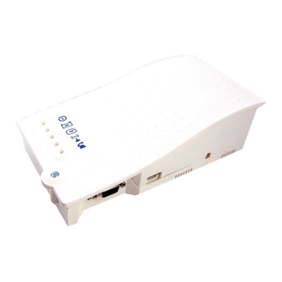
Connector Description DESCRIPTION EXTERNAL ANTENNA BATTERY POWER SUPPLY CANBUS J9/J1A PHONE LINE RS232 CONNECTOR Note: To access dipswitches and connectors, open the Cellular Gateway case by unfastening the front screw using a Phillips screwdriver and removing the lid. Note: Connect to RS232 (J10) to use as a data pass through. Distance limitation is approximately 1,000 feet. Actual numbers will vary based on the cable and gauge used. -
Page 6: Led Indicators
LED Indicators The Cellular Gateway has five indicator LEDs that constantly report the device status. The indicators will be red, amber, or green. Each indicator will be fully on, fully off, or flashing. The table below provides an overview of what each colored LED indicates: RUN LED FLASHING... -
Page 7: Wiring Diagrams
Wiring Diagrams Elevator Application Wiring Diagram: Antenna Traveling Cable Machine Elevator Room Single Pair 120vac Power Cellular Do not exceed 1,000’ Gateway Single Pair AlphaRefuge 2100 System Wiring Diagram: Antenna RCC Command Center DISCONNECT CALL TO RESCUE RCB Call Box SERVICES RESCUE SERVICES SUB-MASTER 1... - Page 8 AlphaRefuge 2400 System Wiring Diagram: Two Wire Connection Command Antenna Center Two Wire Connection Do not 1 Wire Pair (22/24 ga.) exceed 1,000’ Single Cellular Pair Distribution Single Pair Gateway Module Two Wire Connection Power Cord Connection (Provided) Power Supply with UPS Two Wire Connection...
- Page 9 Elevator Application Wiring Diagram: Antenna **External Power Required** Traveling Cable Machine Elevator Room Single Pair 120vac Power Do not exceed 1,000’ Cellular Gateway Single Pair Page 9...
-
Page 10: Appendix
Appendix Installation: This equipment is intended for installation in restricted areas by qualified personnel. Environmental Conditions: This device is designed to be used indoors (32° F to 113° F with relative humidity between 20% and 80% not condensing). Sudden changes of temperature and humidity should be avoided. Cleaning and Maintenance: Use a soft dry cloth.
Need help?
Do you have a question about the GSM4INTLTE-2 and is the answer not in the manual?
Questions and answers