
Summary of Contents for GM8 Group DR-DWS-1000
- Page 1 SUBMERSIBLE WATER PUMP DR-DWS-1000 For enquiries, please call us on 01462 429765 or email us at cs@gm8group.com...
-
Page 2: Specification
This machine was designed for pumping clear or dirty water. It is ideally suited to pumping out garden ponds where the water is free of debris. These pumps are not designed for use in fish ponds. 4.2 SPECIFICATION SKU: ......................... DR-DWS-1000 Motor: Rated voltage ....................... 230V Rated frequency......................50Hz Rated input ......................1000W Output aperture size ......................25mm... -
Page 3: General Safety Instructions For Power Tool Use
HEALTH AND SAFETY INFORMATION Have this tool repaired by a qualified person. This tool is designed to conform to the relevant international and local standards and as such should be maintained and repaired by someone qualified; using only original parts supplied by the manufacturer: This will ensure the tool remains safe to use. - Page 4 HEALTH AND SAFETY INFORMATION 3) Personal safety continued... e) Do not overreach. Keep proper footing and balance at all times. This enables better control of the power tool in unexpected situations. f) Dress properly. Do not wear loose clothing or jewellery. Keep your hair, clothing and gloves away from moving parts.
-
Page 5: Additional Safety Instructions For Submersible Water Pumps
HEALTH AND SAFETY INFORMATION 5.2 ADDITIONAL SAFETY INSTRUCTIONS FOR SUBMERSIBLE WATER PUMPS When carrying or lifting the submersible pump always use the transport handle, DO NOT carry or lift using the power cable or float switch cable. Before connecting to the power supply: •... -
Page 6: Connection To The Power Supply
HEALTH AND SAFETY INFORMATION 5.3 CONNECTION TO THE POWER SUPPLY Caution: Risk of electric shock. Do not open. 230V: 98911, 98912, 98914, 98917, 98918, 98919 & 98921. These machines come supplied with a UK standard 3 pin plug fitted. Designed for connection to a domestic power supply rated at 230V AC. -
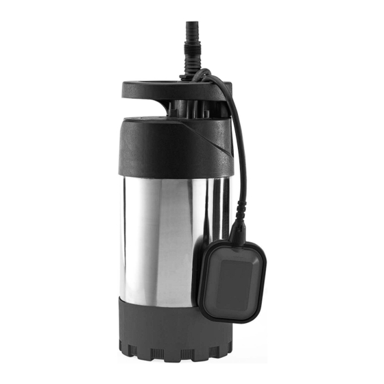
Page 7: Main Component Descriptions
TECHNICAL DESCRIPTION 6.1 IDENTIFICATION Outlet. Carry handle. Float switch cable clamp presses. Approved 3 pin non-rewireable moulded plug and cable (not fitted to 110V models) Automatic cut off float switch Filter base plate. Hose adaptor. 6.2 MAIN COMPONENT DESCRIPTIONS The CARRY HANDLE for ease of transportation. The HOSE ADAPTOR allows the use of different size hoses. - Page 8 UNPACKING AND CHECKING 7.1 PACKAGING Carefully remove the machine from the packaging and examine it for any sign of damage that may have happened during shipping. Lay the contents out and check them against the parts shown below. If any part is damaged or missing do not attempt to use the machine. The packaging material should be retained at least during the guarantee period: in case the machine needs to be returned for repair.
- Page 9 READYING THE PUMP 8.1 INSTALLATION OF PARTS – FIG.1 WARNING: DO NOT MAKE ANY OF THE FOLLOWING ADJUSTMENTS WITH THE PUMP CONNECTED TO THE POWER SUPPLY. Before first use it is important to carry out a visual check of the product to ensure that the product has not suffered any transit damage and is safe to use.
- Page 10 INSTALLING THE PUMP 9.1 PUMPING DISTANCE AND VOLUME – FIG.2 FIG.2 Fig.2 provides a guide for volumes pumped in relation to hose height. 25L/min Horizontal pumping distance is directly affected by the working head height (Maximum 55L/min head height minus actual working head height ×...
- Page 11 INSTALLING THE PUMP 9.2 FLOATING SWITCH - FIGS. 3 - 6 FIG.3 An automatic float switch is fitted to the pump. This enables the pump to switch off automatically when the water has reached the minimum level. As the water level drops the float switch will fall with the water level.
- Page 12 INSTALLING THE PUMP 9.3 SET CUT OFF FLOAT HEIGHT FIG. 7 FIG.7 The float switch can be set to a specific cut off level by increasing or decreasing the length of cable between the cable clamp recess and float switch 9.4 SET INTEGRAL FLOAT HEIGHT FIG.
- Page 13 INSTALLING THE PUMP 9.5 PLACEMENT - FIGS. 9 - 11 FIG.9 The pump must be fully submersed before the power is switched on. DO NOT turn on when dry. When submersing or lifting the pump it will be FIG.10 necessary to use a rope or chain, this must be attached to the transport handle.
-
Page 14: Switching On The Pump
INSTALLING THE PUMP 9.6 CONNECTING TO POWER VIA RCD – FIG.12 FIG.12 Once you have the pump safely situated and the float switch adjusted, if required, you are ready to turn on the pump. Plug your pump into a Residual Current Device (RCD) and connect to your mains supply. - Page 15 10. MAINTENANCE 10.1 CLEARING OBSTRUCTIONS IN THE IMPELLER HOUSING – FIG.13 FIG.13 WARNING: For your own safety, remove plug from power supply before maintaining your submersible pump. If the impeller becomes blocked or obstructed, remove base plate by removing the screws. DO NOT lever the impeller as this will cause damage due to its brittle construction.
-
Page 16: Troubleshooting Checklist
12. TROUBLESHOOTING 12.1 TROUBLESHOOTING CHECKLIST WARNING: For your own safety, always turn the main switch on the machine "Off" and remove the plug from the power supply before carrying out any servicing or maintenance. Motor does not 1. Make sure the motor is Service agent.
Need help?
Do you have a question about the DR-DWS-1000 and is the answer not in the manual?
Questions and answers