Table of Contents
Advertisement
Quick Links
Bulletin TI-GCGS-E
Technical Information
Parker Balston
GC-4000 and FID-4000
Installation, Operation, and Maintenance Manual
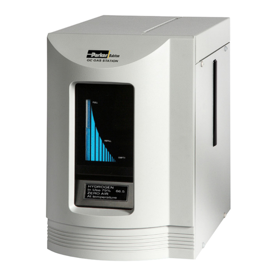
FRONT VIEW
Figure 1 - FID Gas Station
GC Gas Stations
®
These instructions must be thoroughly read and understood before install ing and operating
this product. Any modification of the product will void the warranty. Failure to operate
this product in accordance with the instructions set forth in this manual and other safety
governing bodies could jeopardize the safety of the operator and void the safety certification
of this product.
If you have any questions or concerns, please call the Technical Services Department at
800-343-4048, 8AM to 5PM Eastern Time or email at balstontechsupport@parker.com
(North America only). For other locations, please contact your local representative.
Do not use a Hydrogen gas storage vessel in conjunction with the Hydrogen generator.
Stored quantities of hydrogen pose an explosion hazard.
Normal precautions for any hydrogen supply should be taken when using the hydrogen
generator. DO NOT USE IN A SEALED OR UNVENTED ROOM.
CAUTION: DO NOT USE AN OPEN FLAME OR OTHER IGNITION SOURCE WITHIN 10 INCHES
(25cm) OF THE OXYGEN VENT!
Shelf Life is 3 months. The generator should be run every 3 months. See Operating and
Storage instructions for more detail
Installation, Operation and Maintenance Manual
GC Gas Stations GC-4000, FID-4000
RIGHT SIDE VIEW
1
www.labgasgenerators.com
Advertisement
Table of Contents

Summary of Contents for Parker Balston GC-4000
- Page 1 Installation, Operation and Maintenance Manual Bulletin TI-GCGS-E Technical Information GC Gas Stations GC-4000, FID-4000 Parker Balston GC Gas Stations ® GC-4000 and FID-4000 Installation, Operation, and Maintenance Manual FRONT VIEW RIGHT SIDE VIEW Figure 1 - FID Gas Station These instructions must be thoroughly read and understood before install ing and operating this product.
-
Page 2: General Description
Final Filtration The final filter on the Parker Balston GC Gas Generator is a high efficiency filter which removes particulate contamination to 0.5 micron. This final filter ensures that the outlet air from the Parker Balston Gas Station is particle-free. - Page 3 GC Gas Stations GC-4000, FID-4000 Hydrogen System The Parker Balston GC Gas Station also includes a system to generate and purify hydrogen gas. This portion of the generator includes: water feed system, proton exchange membrane cell, and palladium purifier (See figure 3).
-
Page 4: Installation
Installation, Operation and Maintenance Manual Bulletin TI-GCGS-E Technical Information GC Gas Stations GC-4000, FID-4000 Installation General Note: All installation, operation and maintenance activities for the GC Gas Stations should be performed by suitable personnel using reasonable care. The GC Gas Station is a free-standing bench-top unit. Do not suspend the generator from the wall or ceiling. - Page 5 fittings. Utilities Power -The Parker Balston GC Gas Station may be operated by a 120 VAC, 220 VAC, 230 VAC, or 240 VAC, 50/60 Hz power supply. Main supply voltage fluctuations must be within ±10% of the nominal main supply voltage. The generator is shipped with a tag at the power receptacle which specifies the factory setting of the voltage selector.
-
Page 6: Filling The Water Reservoir
Connect the compressed air supply to the inlet port for the Parker Balston GC Gas Station, which is 1/4” NPT and is located as shown in Figure 4. Inlet tubing and fittings should be clean and rated for 125 psig (8.5 Barg), minimally. The tubing and fittings used downstream from the GC Gas Station should be clean stainless steel or pre-cleaned... - Page 7 Bulletin TI-GCGS-E Technical Information GC Gas Stations GC-4000, FID-4000 The GC Gas Station’s default mode of operation includes an auto water feed system. If that system is NOT used, by the operator, then it will become disabled to prevent repeated, un- necessary actuation of the auto water feed solenoid valve.
- Page 8 When power is supplied to the unit, the catalyst module and the purifier will begin to heat up. The Parker Balston GC Gas Station requires approximately 90 minutes to warm up and achieve hydrocarbon removal to 0.05 ppm (see Figure 5 Power Up / Start Up Sequence) and Hydrogen flow at the specified flow rate.
-
Page 9: Quick Start Instructions
Installation, Operation and Maintenance Manual Bulletin TI-GCGS-E Technical Information GC Gas Stations GC-4000, FID-4000 Turn the pressure regulator in a clockwise direction to increase the outlet pressure. If 100 psig is required, turn the pressure regulator all the way in (clockwise) to the maximum value. -
Page 10: Operation
The outlet air will contain hydrocarbons in excess of 0.05 ppm. The Parker Balston GC Gas Station is designed to operate continuously, 24 hours per day, as long as the compressed air supply is not interrupted. -
Page 11: Operational Summary
Zero air at temperature- indicating the zero air module can produce gas at the required purity. Diagnostics The Parker Balston GC Gas Station has built-in system diagnostics to monitor the operation of the generator and alert the operator both visually and audibly in case of a failure. - Page 12 Electrolytic Proton Exchange Membrane Cell and eliminates the 90 minute warm up period. To shut down the Parker Balston GC Gas Station, turn the power switch to the OFF position. Maintain the compressed air flow through the unit for at least 10 minutes to improve heat dis- sipation.
- Page 13 Installation, Operation and Maintenance Manual Bulletin TI-GCGS-E Technical Information GC Gas Stations GC-4000, FID-4000 Main Reservoir Hydrogen Cell Water Pump PEM Cell Water Pump Solenoid Block Valve Left side Main Reservoir Drain Figure 7 - Shown with main cover removed Hydrogen Purifier...
-
Page 14: Troubleshooting Error Messages
Installation, Operation and Maintenance Manual Bulletin TI-GCGS-E Technical Information GC Gas Stations GC-4000, FID-4000 Troubleshooting / Error Messages All troubleshooting activities should be performed by suitable personnel using reasonable care. Warning: Any troubleshooting or service activity which requires removal of the generator cover should be done using extreme caution. - Page 15 Installation, Operation and Maintenance Manual Bulletin TI-GCGS-E Technical Information GC Gas Stations GC-4000, FID-4000 Symptom Course of Action Change Water Poor quality water added to fill reservoir. See maintenance section for Deionizer Resin Cartridge replacement. Low Cell Pressure Hydrogen Overflow due to a leak detected in system or downstream. If the hydrogen pressure drops below 10 psi, the “Cell Pressure Low”...
-
Page 16: Maintenance
Service should be performed by persons familiar with the service and safety requirements of electromechanical / electrochemical devices. The primary maintenance tasks required by the Parker Balston GC Gas Station are: changing the deionizer resin cartridge, changing the compressed air filter cartridge (annually), changing the zero air filter (annually), and replacing the catalyst module (3 years), replacing... -
Page 17: Water Pump Replacement
Installation, Operation and Maintenance Manual Bulletin TI-GCGS-E Technical Information GC Gas Stations GC-4000, FID-4000 Remove 2 screws, using a “stubby” screw driver, holding the catalyst assembly module cover to the base of the hydrogen purifier. Slowly lower the module though the access opening in the base of the generator- as far as needed to free the module from the hydrogen purifier. - Page 18 Installation, Operation and Maintenance Manual Bulletin TI-GCGS-E Technical Information GC Gas Stations GC-4000, FID-4000 Water Refill See “Filling the Water Reservoir” (Page 7) for operation details. Refill the water in the generator whenever the ADD WATER message is displayed on the front panel.
-
Page 19: Maintenance Notes
Installation, Operation and Maintenance Manual Bulletin TI-GCGS-E Technical Information GC Gas Stations GC-4000, FID-4000 Fuse Replacement Occasionally, the fuses in the GC Gas Station may burn out. The fuses are located in the power receptacle on the back side of the generator. Before servicing the fuse, turn the unit off and disconnect the power cord from both the power supply and the generator power receptacle. -
Page 20: Explanation Of Warning Symbols
Installation, Operation and Maintenance Manual Bulletin TI-GCGS-E Technical Information GC Gas Stations GC-4000, FID-4000 Don’t Forget To: 1 Complete and mail or fax in your warranty registration card (978-478-2501). 2 Keep your product certification in a safe place. 3 Call the Technical Services Department at 800-343-4048, 8AM to 5PM Eastern Time with any questions (North America only) or email at: balstontechsupport@parker.com.
Need help?
Do you have a question about the GC-4000 and is the answer not in the manual?
Questions and answers