
Summary of Contents for ClearSound LA V3
- Page 1 Clear Sound Ltd. Sofia 1700, Bulgaria Prof. Hristo Vakarelski Str. 4 VAT BG201105102 www.clearsound.bg office@clearsound.bg Clear Sound LA V3 Line Array Operation Manual Page 1 of 46 Clear Sound Ltd. LA V3 Operation Manual...
- Page 2 3.2 Rigging Safety 3.3 Electrical Safety 3.4 Other Activities Concerning Safety 3.5 Disposal and Recycling 4. Clear Sound LA V3 System Description 4.1 Brief System Overview 4.2 System Components 5. Technical Specifications, Outline Drawings and Frequency Response Graphics 5.1 Technical Specifications 5.2 Outline Dimension Drawings...
- Page 3 9.3 General Principles 9.4 Routing 9.5 Setting up the Crossover Points 9.6 Gains 9.7 Delay Times 9.8 Setting the Limiters / Compressors 10. Subwoofers 10.1 General Safety 10.2 Recommended Subwoofers Page 3 of 46 Clear Sound Ltd. LA V3 Operation Manual...
- Page 4 Please, contact Clear Sound in case of any questions or difficulties concerning the information in this manual! The purpose of this manual is to equip you, the user of LA V3 Line Array, with the most important information of how it is used, its parameters, and yours and your property safety. We assume in advance that you have some basic knowledge, skills and training in this field.
- Page 5 The crew should have basic skills in first aid and rescue. 3.2 Rigging Safety LA V3 must be rigged and lifted up ONLY by professional riggers or by trained personnel under a supervision of a professional rigger. The rigging is a work with a high potential of risk for the people and for the equipment.
- Page 6 LA V3 is 3-way fully active connected (tri-amp) speaker operating with external amplifiers connected to it with long cables. The amps are not a part from LA V3 Line Array; it can operate with many different types. Here the theme about the amps and the power is described from the safety point of view because it is significant for the whole system’s safety.
- Page 7 The power plug / connector without proper grounding must not be used. It is widely spread to remove the ground connection from the power plug in the case of hum and other Page 7 of 46 Clear Sound Ltd. LA V3 Operation Manual...
- Page 8 LA V3 speaker boxes are designed to be right and left. The left and right speakers’ orientation should be done in such a way that Hi-frequency section to be inside, towards the stage.
- Page 9 Figure 1 is a right one. 4.2 System Components One LA V3 speaker consists of three sections: LO, MID and HI. For subs, please refer to Chapter 10. LO section is designed with 2 custom made 10” loudspeakers loaded with frontloaded horn.
- Page 10 Prof. Hristo Vakarelski Str. 4 VAT BG201105102 www.clearsound.bg office@clearsound.bg 5.2 Outline Dimensions Drawings For components description, please refer to corresponding chapters of this manual. Figure 1. LA V3 – Isometric View Page 10 of 46 Clear Sound Ltd. LA V3 Operation Manual...
- Page 11 Sofia 1700, Bulgaria Prof. Hristo Vakarelski Str. 4 VAT BG201105102 www.clearsound.bg office@clearsound.bg Figure 2. LA V3 – Front View Figure 3. LA V3 – Side View Figure 4. LA V3 – Top View Page 11 of 46 Clear Sound Ltd.
- Page 12 Clear Sound Ltd. Sofia 1700, Bulgaria Prof. Hristo Vakarelski Str. 4 VAT BG201105102 www.clearsound.bg office@clearsound.bg Figure 5. Line Array Flying Frame - Flybar Page 12 of 46 Clear Sound Ltd. LA V3 Operation Manual...
- Page 13 Prof. Hristo Vakarelski Str. 4 VAT BG201105102 www.clearsound.bg office@clearsound.bg Figure 6a. Ball-Lock Pin types and position. Figure 6b. Ball-lock Pin F14S (left picture) and Ball-lock Pin F14L (right picture). Page 13 of 46 Clear Sound Ltd. LA V3 Operation Manual...
- Page 14 Clear Sound Ltd. Sofia 1700, Bulgaria Prof. Hristo Vakarelski Str. 4 VAT BG201105102 www.clearsound.bg office@clearsound.bg Page 14 of 46 Clear Sound Ltd. LA V3 Operation Manual...
- Page 15 Clear Sound Ltd. Sofia 1700, Bulgaria Prof. Hristo Vakarelski Str. 4 VAT BG201105102 www.clearsound.bg office@clearsound.bg Figure 7. Dolly Board Page 15 of 46 Clear Sound Ltd. LA V3 Operation Manual...
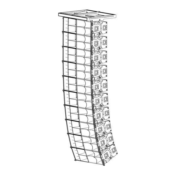
- Page 16 Clear Sound Ltd. Sofia 1700, Bulgaria Prof. Hristo Vakarelski Str. 4 VAT BG201105102 www.clearsound.bg office@clearsound.bg Figure 8. LA V3 10 right speakers rigged together. FOH right side. Page 16 of 46 Clear Sound Ltd. LA V3 Operation Manual...
- Page 17 VAT BG201105102 www.clearsound.bg office@clearsound.bg 5.3 Frequency Response Graphics Figure 9a. LO Section - Frequency Response of LO Section of 4xLA V3, free space (4xPi), 8Vrms, at 4m on axis, unprocessed Page 17 of 46 Clear Sound Ltd. LA V3 Operation Manual...
- Page 18 (ground, stage, etc.) one over the other using their hardware. The choice between flying and stacking depends on the venue dimensions, the area covered, the scene height and other specific factors. Page 18 of 46 Clear Sound Ltd. LA V3 Operation Manual...
- Page 19 The stage structure, if it is strong enough. Refer to stage documentation, stage owner, stage engineer. LA V3 Line Array is a heavy one and only a few stage types can be used for hanging.
- Page 20 All chain hoists’ hooks are down to the ground. e) You know the correct angles between each speakers. Each angle is already known, determined with suitable calculators or in other way. Page 20 of 46 Clear Sound Ltd. LA V3 Operation Manual...
- Page 21 Figure 11. Before hanging the speaker, you should take out every moving bar from the speaker frame. Lock them in position using Ball Lock Pin F-14S, as shown on Figure 12. Page 21 of 46 Clear Sound Ltd. LA V3 Operation Manual...
- Page 22 The speaker is over the dolly board. Figure 12. LA V3 speaker with the moving bars outside the speaker frame. Bars in working position, locked with 2 pcs Ball Lock Pins F-14S. Two more pins of the same type lock the bars from the other side.
- Page 23 Move the first / upper speaker near the flybar. Connect carefully both upper moving bars of the speaker to the front holes of the flybar using Ball Lock Pins F-14L, as shown on Figure 14. Note different pins type. Page 23 of 46 Clear Sound Ltd. LA V3 Operation Manual...
- Page 24 Lift up the flybar with the first speaker using all chain hoists together. The flybar have to be horizontal all the time. Remove the dolly board. Flybar must be approx. 1m from the ground. Page 24 of 46 Clear Sound Ltd. LA V3 Operation Manual...
- Page 25 Now lift up the back side of the speaker up and lock it with 2 Ball Lock Pins F-14L to the back holes of the Flybar. Use holes closer to the front if you use LA V3 speaker. Use holes closer to the back of the flybar if you use LAV2 speaker.
- Page 26 Please note that Ball Lock Pin F13-L and Ball Lock Pin 14-L are the same devices. Lift up the flybar with the first speaker so another speaker with dolly board can be attached from down. Step 5. Attaching the second speaker Page 26 of 46 Clear Sound Ltd. LA V3 Operation Manual...
- Page 27 Same way connect the third speaker to the second one and so on. Connect the cables. Lift up the speakers with all chain hoists simultaneously, keeping the flybar horizontal all the time. Page 27 of 46 Clear Sound Ltd. LA V3 Operation Manual...
- Page 28 The Flybar has to remain horizontal all the time. This is the main function of the person supervising the process from the side, see Chapter 3.2. Step 8. Setting up the site angle Please, see Chapter 6.6 Page 28 of 46 Clear Sound Ltd. LA V3 Operation Manual...
- Page 29 Ball Lock Pin F14-S in, see Figure 20. The ball-lock pin must lock the moving bar into the frame tightly and then the pushbutton of the pin have to be released. Page 29 of 46 Clear Sound Ltd. LA V3 Operation Manual...
- Page 30 Please, refer to Chapter 3.3 for Electrical Safety. 7.2 Speaker Internal Diagram LA V3 is 3-way fully active connected (tri-amp) speaker. All drivers are internally connected and their external terminals are wired to NL-8 connectors as shown on Figure21. Page 30 of 46 Clear Sound Ltd.
- Page 31 VAT BG201105102 www.clearsound.bg office@clearsound.bg Figure 21. LA V3 Internal Electrical Wiring Diagram 7.3 General System Block Diagram The maximum number of speakers per side is 10 (ten). The minimum number of speakers that forms Line Array is 4 (four). You may use one speaker or two speakers per side but there will be no good sound coverage at the distance.
- Page 32 Standard cable manufactured by Clear Sound is wired 1+ to be positive and 1- to be negative signal to the LO section. Other’s connections (say 1+ positive and 2+ negative signal) are available on request. Page 32 of 46 Clear Sound Ltd. LA V3 Operation Manual...
- Page 33 Clear Sound Ltd. Sofia 1700, Bulgaria Prof. Hristo Vakarelski Str. 4 VAT BG201105102 www.clearsound.bg office@clearsound.bg Figure 23. System Connection with Two Speakers Page 33 of 46 Clear Sound Ltd. LA V3 Operation Manual...
- Page 34 Clear Sound Ltd. Sofia 1700, Bulgaria Prof. Hristo Vakarelski Str. 4 VAT BG201105102 www.clearsound.bg office@clearsound.bg Figure 24. System Connection with Three Speakers Page 34 of 46 Clear Sound Ltd. LA V3 Operation Manual...
- Page 35 Clear Sound Ltd. Sofia 1700, Bulgaria Prof. Hristo Vakarelski Str. 4 VAT BG201105102 www.clearsound.bg office@clearsound.bg Figure 25. System Connection with Four Speakers Page 35 of 46 Clear Sound Ltd. LA V3 Operation Manual...
- Page 36 Clear Sound Ltd. Sofia 1700, Bulgaria Prof. Hristo Vakarelski Str. 4 VAT BG201105102 www.clearsound.bg office@clearsound.bg Figure 26. System Connection with Six Speakers. Please note 2 group of amps. Page 36 of 46 Clear Sound Ltd. LA V3 Operation Manual...
- Page 37 Clear Sound Ltd. Sofia 1700, Bulgaria Prof. Hristo Vakarelski Str. 4 VAT BG201105102 www.clearsound.bg office@clearsound.bg Figure 27. System Connection with Eight Speakers. Please note 2 group of amps. Page 37 of 46 Clear Sound Ltd. LA V3 Operation Manual...
- Page 38 Prof. Hristo Vakarelski Str. 4 VAT BG201105102 www.clearsound.bg office@clearsound.bg Figure 28. System Connection with ten Speakers per side. Note the 3 groups of amps. The maximum number of speakers per side is 10. Page 38 of 46 Clear Sound Ltd. LA V3 Operation Manual...
- Page 39 8 connector. On the other side (the amp side) the attack cable is divided into three cables each one with NeutrikTM SpeakONTM NL-4 connector, and in this way supplying tree different sections of LA V3 (LO, MID, HI) with different signals from the different amps. Please, see Figure 29.
- Page 40 Figure 30. Link Cable, Connectors and Pins Description 7.5 Amplifiers For supplying LA V3 you may use different types of amps according to your needs and other specific conditions. Figure 31 shows the most important system parameters: Section Rated Power (AES) and Section Impedance vs. Number of Speakers connected in parallel.
- Page 41 (crest-factor, power factor, etc.). Otherwise, the voltage drop at the end of the cable at the peak moments will decrease the mains voltage which supplies the amps during the peaks, which is unacceptable. Some amps with SMPS (switching-mode power supply) draw Page 41 of 46 Clear Sound Ltd. LA V3 Operation Manual...
- Page 42 (initial start-up) current when you switch-on the amps. The usage of residual current breakers is mandatory in some areas. Please, check your local regulations! 8.6 Using a Generator Page 42 of 46 Clear Sound Ltd. LA V3 Operation Manual...
- Page 43 It is used for setting different delay time for each band because the sound waves paths from the loudspeakers through the different horns are different. As a result of Page 43 of 46 Clear Sound Ltd. LA V3 Operation Manual...
- Page 44 (L+R sum) for the subwoofers. 9.5 Setting up the Crossover Points Each section of LA V3 is carefully designed to operate only in a certain frequency range. See Figure 32 for recommended cross-over points and signal polarity. Recommended Crossover Points...
- Page 45 Line Array speakers. Clear Sound models RLH118SX, HL118BR and HL121 are very good choice. You can use different types of subwoofers depending on your needs. Page 45 of 46 Clear Sound Ltd. LA V3 Operation Manual...
- Page 46 There are many different theories concerning the subwoofers position and the subwoofers’ configuration but they are not subject of this manual. Electrical connections depend on the number and the amps used. Notes Page 46 of 46 Clear Sound Ltd. LA V3 Operation Manual...
Need help?
Do you have a question about the LA V3 and is the answer not in the manual?
Questions and answers