
Related Manuals for Protected Home HomeSitter HS-700

Summary of Contents for Protected Home HomeSitter HS-700
- Page 1 HomeSitter HS-700 Installation and Operations Manual Protected Home A Division of Control Products, Inc. 1724 Lake Drive West Chanhassen, MN 55317 Document No. 42420062A...
-
Page 2: Table Of Contents
Procedures for obtaining performance Changing phone numbers ....16 for warranty ........26 Installation considerations ......16 To return a product to Protected Home HS-700 assembled ........17 ............26 Phone test ..........18 How to request an RGA number ..26 Testing your HS-700 ...... - Page 3 HS-700 HomeSitter is a trademark of Protected Home. Touch Tone® is a registered trademark of AT&T. Copyright © 2009 Protected Home: All rights reserved. No part of this work may be reproduced or used in any form or by any means—graphic, electronic, or mechanical—without written permission from Protected Home.
-
Page 4: Cautions And Warnings
Cautions and warnings Cautions indicate the possibility of poor equipment performance or potential damage to the equipment. Warnings indicate the possibility of injury to persons. The symbols shown below identify Cautions and Warnings: Cautions and warnings appear here and may appear throughout this manual where appropriate. -
Page 5: Description
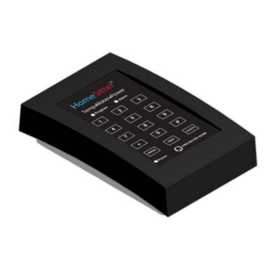
Description Physical description Figure 1 identifies the parts of the HS-700. Figure 1: HS-700 Parts List Table 1: HS-700 Parts and Purpose Part Purpose 1. Key Pad Used to enter the call-to phone numbers, activate a phone test, and cancel an alarm. 2. -
Page 6: General Description
General description The HS-700 monitors your home for a variety of alarm conditions. When an alarm event occurs, the HS-700 calls the three entered phone numbers for the following alarms: Temperature drops below 45ºF (7ºC) or temperature rises above 85ºF (34ºC) DIP switch (selectable) ... -
Page 7: Audible Alarm
Audible alarm The HS-700 produces a 40 db beep during an alarm event. You can turn the audible alarm (beep) OFF for alarm conditions ONLY by setting DIP switch “6” to the DOWN position. What conditions activate the audible alarm? The HS-700 will beep during the following alarm events: ... -
Page 8: How The Hs-700 Handles An Alarm Condition
How the HS-700 handles an alarm condition Stage Description When an alarm occurs, the alarm LED lights up (if not an AC power failure), and the HS-700 emits a beep every so many seconds depending on the alarm type. The HS-700 starts calling the call-list phone numbers in sequence, attempting to deliver an in progress alarm voice message. -
Page 9: Dip Switch Functions And Settings
DIP switch functions and settings The HS-700 has a 7-position DIP switch. The switch settings determine how the HS-700 will respond to specific alarm conditions. Figure 2 shows the DIP switch and Table 3 explains the functions of each switch. Turn the HS-700 upside down as shown in Figure 2 for proper DIP switch orientation. -
Page 10: Initial Setup
Note: A surge protector is recommended, but not provided. You can purchase a surge protector from Protected Home or from a local computer or hardware store. To connect AC power to the HS-700 through the AC power adapter, follow the number sequence shown in Figure 3. -
Page 11: Connections
Batteries Battery handling and safety Do not throw batteries into a fire. Failure to observe this warning could result in an explosion. Note: REMOVE the batteries when the HS-700 is not in service. Battery life If the back-up battery voltage drops below 2.35 volts, a low battery alarm will be sent, even when the unit is powered by the AC power adapter. -
Page 12: Connecting The Water Sensor
Connecting the water sensor To connect the water sensor to the HS-700, do the following: Plug water sensor connector here Water Sensor Note: You can lengthen the cable of the water sensor to 100ft (30.8m), using the equivalent size wire. (24 gauge, 2 conductor wire) Figure 3: Water Sensor Connected to HS-700 Connecting to the standard phone line To connect the HS-700 to a phone line, do the following:... -
Page 13: Connecting The Hs-700 And Another Device To The Same Phone Jack
Connecting the HS-700 and another device to the same phone jack If you need to connect the HS-700 and some other device, such as a telephone, to the same wall phone jack, simply use a phone jack splitter (not provided). To use a splitter, do the following: Step Action... -
Page 14: Phone Services And Your Hs-700
Phone services and your HS-700 DSL and other digital phone services Please note that the HS-700 is designed and certified by the FCC to operate on a standard telephone line, provided by your local telephone company. DSL, Cable, or Digital phone service may work with the appropriate in-line filters. -
Page 15: Programming (Entering Phone Numbers)
Programming (entering phone numbers) You can program the HS-700 with up to three phone numbers (60 digits each), which it uses to communicate alarm messages. Before you start entering phone numbers DO NOT enter phone numbers of emergency services (fire, police or ambulance) into the HS-700. -
Page 16: Deleting Phone Numbers
Deleting phone numbers To delete a phone number, do the following: Step Action Press the PROGRAM key—a beep and the program LED starts flashing. Press the number 1, 2, or 3 key of the location of the phone number that you want to delete—a beep and the program LED is ON, not flashing. -
Page 17: Hs-700 Assembled
HS-700 assembled Figure 8 shows an example of an ideal setup of the HS-700 fully assembled. Place the HS- 700 on any flat surface, preferably a table top near an AC Power outlet and a phone jack as shown in Figure 8. Once the HS-700 is fully assembled and operational (power LED ON), perform a phone test to ensure that the HS-700 can call the call-list phone numbers during an alarm. -
Page 18: Phone Test
Phone test After entering all phone numbers, it is crucial that you test your HS-700 to verify that it can reach the call list phone numbers. Note: The CANCEL key does not function when the HS-700 is in “test mode.” Testing your HS-700 To test the HS-700, do the following: Step... -
Page 19: Calling The Hs-700 During An Alarm Event
Calling the HS-700 during an alarm event To call the HS-700 during an alarm, do the following: Step Action Call the phone number of location where the HS-700 is located—the HS-700 will answer in 5 or 10 rings (DIP switch set) and deliver an alarm specific message. -
Page 20: How To Cancel An Alarm Call Out Sequence
How to cancel an alarm call out sequence You can cancel an alarm call out sequence in two ways: Remotely, press the number “1” key and then the pound (#) key at any time during the alarm message. Locally, press the CANCEL key on the key pad. Canceling an alarm call out sequence while listening to an alarm message To cancel a call out sequence while listening to an alarm message, do the following:...
Need help?
Do you have a question about the HomeSitter HS-700 and is the answer not in the manual?
Questions and answers