Table of Contents
Advertisement
Quick Links
Advertisement
Table of Contents

Subscribe to Our Youtube Channel
Related Manuals for SCHUSTER WKV Series


Summary of Contents for SCHUSTER WKV Series
- Page 1 150 - 230 300 - 348 INSTALLATION AND SERVICING MANUAL...
-
Page 2: Table Of Contents
General Information Warning: this manual contains instructions to be used exclusively by the in- staller and/or a competent person in accordance with the current laws in force. The end user MUST not make any alterations to the boiler. Failure to follow the instructions indicated in this manual, which is supplied with the boiler, could cause injury to persons, animals or damage to property. -
Page 3: General Informationi
General Information GENERAL INFORMATION 1.1 - SYMBOLS USED IN THIS GUIDE When reading this guide particular care has to be given to the parts marked with the followings symbols: DANGER! WARNING! NOTE! Indicates serious danger Indicates a potentially dangerous Suggestions for the for your personal safety situation for the product and the en- user... -
Page 4: Safety Warnings
General Information 1.4 - SAFETY WARNINGS WARNING! The device should not be used by people with reduced physical, mental and sensory, experience and knowledge. These people must be well-informed and supervised during the work. Children must be supervised so they do not play with the appliance. WARNING! The installation, adjustment, and servicing of this appliance must be carried out by a competent person and installed in accordance with the current standards and regulations. -
Page 5: Data Plate
General Information 1.7 - DATA PLATE - The essential requirements of the Directive regarding 2004/108 EC electromagnetic compatibility (Directive The data plate can be found underneath the casing above - The essential requirements of the Efficiency Directive the first module‘s electrical box, a duplicate of the same data (Directive 92/42/EEC) plate can be found on the control instrument‘s inside door. -
Page 6: General Warnings
General Information WARNING If the boiler operates with a forced draught gas burner, the appliance, not appertaining to any category contemplated in the annexe II of the legislative decree n°93 dated 25/02/2000 (implementation of the PED Directive 97/23/EC), and moreover also being contemplated in the Gas Appliances Directive 90/396/EEC), to which the art. - Page 7 2.1 - TECHNICAL FEATURES - For boilers in battery (up to 7), control panel and electronic The WKV series is made up of gas heating units and very low slave, external to the mantle, placed vertically at the side condensing temperature according to dir. 92/42, made entirely...
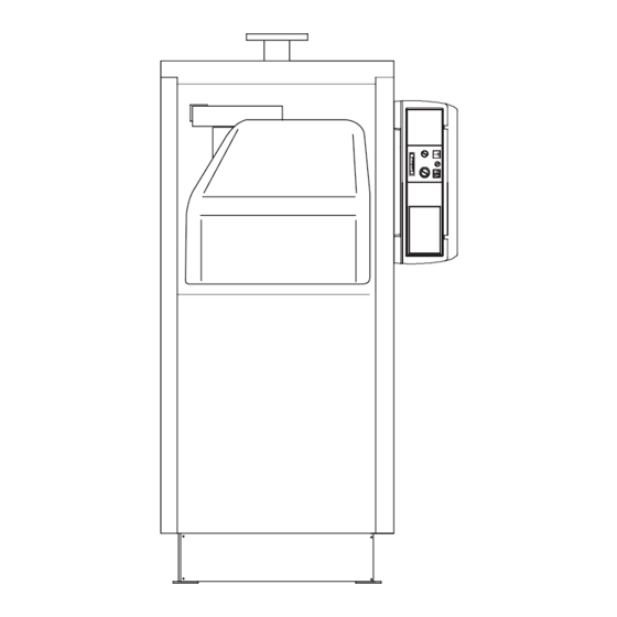
- Page 8 Technical features and dimensions 2.2 - MAIN COMPONENTS AND FUNCTIONING The WKV boilers are built with a blind furnace, in which the burner’s central flame travels towards the bottom and then is distributed in the flue pipes; at the terminal part of the pipes the combustion gas is collected in the flue chamber and then sent to the chimney.
- Page 9 Technical features and dimensions 2.3 - DIMENSIONS 1 Control box T1 C.H flow Cable sheathing leads bulbs 2 Flame control sight glass T2 Average temperature system return Cable sheathing leads bulbs T3 Low temperature system return Chimney connection T4 Expansion vessel connection Burner connection T5 Boiler drainage T10 Condensate drain...
-
Page 10: Performance Data
Technical features and dimensions 2.4 - PERFORMANCE DATA BOILER TYPE WKV150 WKV230 WKV300 WKV348 Boiler family gas category II 2H3P Nominal heat input on LCV Qn Minimum heat input on LCV Qmin Nominal heat output (Tr 60/Tm 80°C) Pn 136,5 209,2 273,6 317,7... -
Page 11: Instructions For The Installer
Instructions for the installer INSTRUCTIONS FOR THE INSTALLER 3.1 - GENERAL WARNINGS The connection between the boiler and chimney/ AThis boiler has to be destined for the use for flue outlet can be made only after this verification which it has been expressively designed for. has been carried out. -
Page 12: General Warnings
Instructions for the installer INSTRUCTIONS FOR THE INSTALLER 3.1 - GENERAL WARNINGS 3.2 - STANDARD CODES FOR INSTALLATION This boiler has to be destined for the use for which it has been expressively designed for. This appliance must be installed in compliance to the manu- Any other use shall be considered improper and facturer’s instructions and therefore dangerous. -
Page 13: Packaging
Instructions for the installer 3.3 - PACKAGING The WKV boilers are delivered fully complete with door and ISOLATION AND CASING smoke chamber already fitted, whilst the casing with the insulation mattress is contained N.B. For the model WKV150, mantle and isolation are in separate cardboard contained in 1 package marked: packaging(s). -
Page 14: Handling And Lifting
Instructions for the installer 3.4 - HANDLING AND LIFTING The boiler can be moved by lifting, via the holes or upper hooks. If necessary, due to the dimensions of the boiler, it is possible to remove the front door to facilitate the introduction in the boiler house. -
Page 15: Boiler Location
Instructions for the installer 3.6 - BOILER LOCATION The boiler must be installed in accordance with the relevant requirements of the Gas Safety Regulations, current I.E.E. Regulations, local water authority by e-laws and it should also comply with any relevant requirements of the local gas supplier, local authority and the relevant Standard Codes of Practice and building regulations. - Page 16 Instructions for the installer Esemple: WKM 230 Flue gas mass flow rate Flue gas mass flow rate = 349,6 K g/h Flue gas mass Chimney height = 25 m flow rate (max) Chimney connect. diam. = 200 mm kg/h 228,8 349,6 Note: The diagram shows indicative values 457,7 529,6...
- Page 17 Instructions for the installer 3.8 - CONDENSARE DRAIN The condensate drain system must be: built in order to prevent the products of combustion dischar- have an inclination toward the drain of at least 30 mm/m (3/8 ging in the ambient or in the sewage(siphon); in./ft).
- Page 18 Instructions for the installer 3.9 - FIRE DOOR: ADJUSTMENT,OPENING & CLOSING IMPORTANT - The door must be opened only when the boiler is cold to avoid causing damages to the fibre lining due to thermal stress. - The door’s fibre lining can crack after a brief period of boiler operation;...
-
Page 19: Gas Conection
Instructions for the installer 3.10 - GAS CONENCTION DANGER! The gas supply pipe must have a section which is adequate to The gas connection must be carried out only the burner’s output. by a qualified registered engineer who will have to respect and comply to the regulations It is however important to comply with the specific standards in force and to the requirements indicated by and requirements in force. -
Page 20: System Connection
Instructions for the installer 3.11 - SYSTEM CONNECTION WARNING! CH pressure relief valve Before connecting the boiler to the heating sy- drainage stem we recommend that the system is flushed In correspondence to the CH pressure relief valve, provision out with a suitable product in order to eliminate should be made to install a discharge pipe with a funnel and a any metallic tooling or welding residues, oil siphon which lead to an adequate drainage. -
Page 21: Determination Of Primary Circuit Pump Or Boiler System Pump
Instructions for the installer 3.12 - DETERMINATION OF PRIMARY CIRCUIT PUMP OR BOILER SYSTEM PUMP The size of the pumps must be determined by The boiler pump must have a delivery head which can ensure installers or technical engineers according to the water flow rate as shown in the graph “Water pressure boiler data and system design. - Page 22 Instructions for the installer WKV230 WATER SIDE PRESSURE LOSSES Q: water flow rate (l/h) WKV300 WATER SIDE PRESSURE LOSSES Q: water flow rate (l/h)
-
Page 23: Frost Protection
Instructions for the installer WKV348 WATER SIDE PRESSURE LOSSES Q: water flow rate (l/h) 3.13 - FROST PROTECTION If the flow temperature (measured at global flow NTC) falls WARNING: below 7°C, the system pump circulates water around the If the boiler has remained unused for a water circuit and all the heat modules will operate at minimum long period, and you notice the presence of output. -
Page 24: Water Treatment
Instructions for the installer 3.15 - WATER TREATMENT To minimize corrosion it is essential to use a scale inhibitor, however in order for this to function correctly, the metallic The chemical-physical characteristics of the filling water and surfaces have to be clean. reinstatement water in heating systems are of fundamental importance for guaranteeing correct and safe boiler operation. -
Page 25: Casing Assembly
Instructions for the installer 3.16 - CASING ASSEMBLY C. Fit the self-tapping screws onto the internal profiles of the 2 side panels (4 and 5 ). (With panel on the right side) A. Fit the insulation blanket (1) onto the boiler shell and secure in to place using the elasticated straps (2) provided, ensu- ring that the metal clips grip in to the external surface of the insulation. - Page 26 Instructions for the installer E. After removal of the two side screws from the control panel F. Fit the right hand side panel (5) to the lower panel and fix it rotate its cover towards the front to the upper squadretta on the right hand side of the boiler body, inserting the lower bend inside the bottom L profiles.
- Page 27 Instructions for the installer Guide the burner plug through the side cable clamp H. Fit the top panel (8) and fix it onto the side panels (4 & 5). plate(6) and clamp the cable using the cable clamp supplied. Fix the side cable clamp plates to the casing side panels.
- Page 28 Instructions for the installer M. Fit the lower right hand side rear panel (11) onto the right O. Position the top panels (14 and 15) and press them hand side rear panel (5), to the left hand side rear panel (10) against the side panels.
- Page 29 Instructions for the installer R) after removing the cover disconnect the connector “4”, un- U) plug the connector “4” on the unit, screw the 2 nuts “5” and remove the bracket “6”, V) replace the cover “2” access to the terminal unit, and secure with the two screws “1”.
- Page 30 Instructions for the installer 3.17 - SYSTEM FILLING AND DRAINING Warning! To fill the system it is necessary to fit a filling cock on the Do not mix the CH system’s water with anti-fre- system’s return. eze or anti-corrosion solutions using wrong concentrations! It could cause damage to the The boiler is equipped with its own drain tap, whose position is washers and could provoke noise during nor-...
-
Page 31: Electrical Connections
Instructions for the installer 3.18 - ELECTRICAL CONNECTIONS separation in both poles, in an easy accessible position in order to make quick and safe the ser- vicing operations. General warnings The elctrical safety of the appliance is assured only when it is The supply cable must be replaced only by hi- correctly earthed, according to the electrical rules in force. - Page 32 Instructions for the installer Outdoor sensor connection Single boiler Gain access to the rear of the eBus and remove the DANGER! terminals numbered from 5 to 11. Switch off and disconnect the electricity sup- ply before carrying out any operations on the Outdoor sensor connection: insert the cables between electrical parts.
- Page 33 Instructions for the installer Pump Connection Single Boiler FIXED - For the fixed flow rate pump connection, place the RATE PUMP cables between pin 1.2 and terminal M1. Boiler battery Modulating Pump The BCM (optional kit) board, elaborates the data con- cerning the thermal drop (Dt between primary flow and return) and provided power.
-
Page 34: Functional Low Wiring Diagram
Instructions for the installer 3.19 - FUNCTIONAL FLOW WIRING DIAGRAM E.ACC = Ignition electrode E.RIV = Ionization electrode = Main switch = Flue switch = Gas switch = CH sensor = CH return sensor = Condensate level sensor = Limit thermostat TR.ACC = Ignition transformer = Gas valve = Modulating fan detection/adjustment... -
Page 35: Types Of Installation
Instructions for the installer 3.20 - TYPES OF INSTALLATION Single boiler Boiler Cascade Control panel Control panel fitted with an fitted with an eBus heating eBus heating controller controller Slave Panel BCM cascade manager (kit 00361602) - Page 36 Instructions for the installer Electrical connections for boilers installed in a cascade formation The cable for the connection between the boiler and the BCM must have the following characteristics: PVC HT CABLE 3x0,5 BOILER 1 remove the bridge between contacts IN and OUT Y1 terminal BOILER 2...
-
Page 37: Installation Examples
Instructions for the installer 3.21 - INSTALLATION EXAMPLES (Functional diagram) Boiler connection to the heating system, with 1 direct high temperature heating zone NB: In case of a single system return (low or medium temperature), the connection must ALWAYS be carried out on the inlet and the lower back of the boiler (stub “low-temperature system return”). - Page 38 Instructions for the installer...
-
Page 39: Initial Lighting
Instructions for the installer 3.26 - INITIAL LIGHTING PRELIMINARY CHECKS The first ignition must be carried out by a qualified use and operation of the boiler and in particular detail: technician. Failure to do so could cause injury to persons, animals or damage to property. The Hand over to the person in charge of the appliance the manufacturer shall not be held liable for any injury booklet: “INSTRUCTIONS GUIDE FOR THE PERSON IN... -
Page 40: Burner Pressure Adjustment
Instructions for the installer 3.23 - BURNER PRESSURE ADJUSTMENT WKV 150 M A X I M U M O U T P U T ADJUSTMENT SCREW WARNING! All the instructions indicated below are for the exclusive use of qualified service technicians or installers. - Page 41 Instructions for the installer In case of gas valve replacement or difficult ignition: Tighten the maximum adjustment screw “A” in a clockwise direction until you arrive to the abutting end, than slacken for 7 turns. Verify boiler ignition; if the boiler goes into lockout slacken the screw “A”...
- Page 42 Instructions for the installer B) Min output adjustment M I N I M U M O U T P U T ADJUSTMENT SCREW Via the e-bus controller Change the “Test” mode and run the boiler at minimum output (refer to procedure illustrated on page 43).
- Page 43 Instructions for HSCP calibration/adjustment 3.25 - ACTIVATION CHIMNEYSWEEPER MODE Press key A (store) Turn the C until “Manual control” appears on the display. For activating the “CHIMNEYSWEEPER MODE” proceed as follows: Press key B (menu) Select the activation command of the function Turn the knob C until the symbol appears...
- Page 44 Instructions for HSCP calibration/adjustment 3.26 - PROGRAMMING THE OPERATOR PARAMETERS ATTENTION! OPERATIONS TO BE CARRIED OUT ONLY BY TECHNICIANS TO VERIFY AND MODIFY (IF REQUIRED) THE OPERATING PARAMETERS Press key A (2nd zero) appears on the display Press key A (3rd zero) appears on the display Press key A (4th zero) appears on the display...
- Page 45 Instructions for HSCP calibration/adjustment DEFAULT SETTINGS Position Identification Parameter description WKV 150 WKV 230 WKV 300 WKV 348 CH: Minimum Setpoint CH: Maximum Setpoint Pump: Overrun System Config. (single master) System Config. (master in battery) System Config. (slave) Ignition modulation Standby modulation Maximum Modulation Minimum Modulation...
-
Page 46: Inspection And Maintenance
Inspections and maintenance INSPECTIONS AND MAINTENANCE Inspection and maintenance instructions Inspections and maintenance performed professionally and according to a regular To assure long-term functioning of your applian- schedule as well as the use of original spare ce and to avoid altering its approved status, only parts are of the utmost importance for fau- original spare parts must be used. - Page 47 Inspections and maintenance Checking status of gaskets and insulation fibres Boiler body maintenance The insulation fibre of the door can show cracks Danger! after a short time of operation; this however does Before performing any maintenance, make not reduce its insulation capacity nor jeopardise sure the boiler and its components have its lifespan.
- Page 48 Error codes ERROR CODES 5.1 - ERROR CODES DISPLAY Reset key Failure notification Error description Error code Error codes of EBUS control unit are indicated below together with its meaning and corrective actions. Code: Meaning: Code: Meaning: Insufficient gas pressure Sanitary sensor failure (only if the boiler is coupled with an outer storage tank) Solution:...
- Page 49 Error codes Code: Meaning: Code: Meaning: Excessive water temperature detected by the he- Safety thermostat intervention (TL) ating sensor (SR) (> 95°C) Solution: Solution: Press the unblock key on the panel Check water circulation in installation Code: Meaning: Heating system failure (SR) Code: Meaning: Loss of the flame signal during operation...
- Page 52 The manufacturer declines every responsibility for the possible inaccuracies if owed to errors of transcript or press. Also reserves the right to bring those changes that it will hold necessary to it own products or profits, without jeopardizing its essential characteristics Schuster - via Padana Inferiore 52/C - 29012 Caorso (PC) - Italy - e-mail: info@schusterboilers.com - www.schusterboilers.com...
Need help?
Do you have a question about the WKV Series and is the answer not in the manual?
Questions and answers