Table of Contents
Advertisement
Owner's Manual &
Safety Instructions
22i
Model
HE091
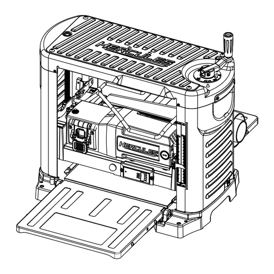
12 1/2" Portable Thickness Planer
WARNING:
To prevent serious injury,
User must read and
understand Owner's Manual. SAVE THIS MANUAL.
When unpacking, make sure that the product is intact and
undamaged. If any parts are missing or broken, please call
1-888-866-5797 as soon as possible. Reference 59313.
Advertisement
Table of Contents

Summary of Contents for Hercules HE091
- Page 1 Owner’s Manual & Safety Instructions Model HE091 12 1/2" Portable Thickness Planer WARNING: To prevent serious injury, User must read and understand Owner’s Manual. SAVE THIS MANUAL. When unpacking, make sure that the product is intact and undamaged. If any parts are missing or broken, please call...
-
Page 2: Important Safety Information
IMPORTANT SAFETY INFORMATION GENERAL TOOL SAFETY WARNINGS 10. WEAR PROPER APPAREL. Do not wear loose clothing, neckties, rings, bracelets, or other jewelry which may get caught in moving Read all safety warnings and all instructions. parts. Nonslip footwear is recommended. Failure to follow the warnings and instructions may result Wear protective hair covering to contain long hair. -
Page 3: Vibration Safety
7. This tool is intended for use on a circuit that has Grounding an outlet that looks like the one illustrated above in 125 VAC 3-Prong Plug and Outlet. The tool has a grounding plug that looks like the plug illustrated above in 125 VAC 3-Prong Plug and Outlet. -
Page 4: Planer Safety Warnings
13. Industrial applications must follow OSHA guidelines. Planer Safety Warnings 14. Maintain labels and nameplates on the tool. These carry important safety For Your Own Safety Read Instruction information. If unreadable or missing, contact Manual Before Operating Harbor Freight Tools for a replacement. 1. -
Page 5: Specifications
Symbology WARNING marking concerning Risk of Fire. Do not cover ventilation ducts. Volts WARNING marking concerning Risk of Electric Shock. Alternating Current Specifications Amperes Electrical Rating 120VAC / 60Hz / 15A Motor Speed 21000 RPM n 0 xxxx/min. No Load Revolutions per Minute (RPM) 1/8"... -
Page 6: Operation
OPERATION Read the ENTIRE IMPORTANT SAFETY INFORMATION section at the beginning of this manual including all text under subheadings therein before set up or use of this product. Tool Set Up Installing Dust Chute TO PREVENT SERIOUS INJURY FROM 1. Loosen the screws on the Blade Guard sides. ACCIDENTAL OPERATION: 2. -
Page 7: Workpiece And Work Area Set Up
Leveling Table Extensions 1. Place a level (sold separately) across Planer Table and Infeed Table, then check level. Level Outfeed Table Planer Table Infeed Table 2. Loosen Lock Nuts. 3. Adjust as needed by lifting Infeed Table and adjusting Leveling Bolts beneath it. 4. -
Page 8: General Operation
7. Remove workpiece, then turn Depth General Operation Adjustment Handle counterclockwise. One full turn will remove 1/16″ of material. NOTICE: Do not remove more than 1/8″ of material at TO PREVENT SERIOUS INJURY FROM HAZARDS one time (1-1/2 turns of Depth Adjustment Handle). SUCH AS KICKBACK: Do not plane workpieces shorter than 15″, narrower NOTICE: Keep long workpieces level by... - Page 9 5. Using included T-Wrench, remove eight Installing or Replacing the Blade Screws on Gib, then flip wrench over and use the magnet to remove Gib. 1. Turn Planer off and unplug from its electrical outlet. 2. Remove Screws on Blade Guard sides, and Knob Screws from Dust Chute.
-
Page 10: Maintenance And Servicing
Internal Maintenance MAINTENANCE AND SERVICING 1. Remove the two Screws on Side Cover. Procedures not specifically explained in this manual must be performed 2. Lift up and tilt bottom out to remove Side Cover. only by a qualified technician. TO PREVENT SERIOUS INJURY FROM ACCIDENTAL OPERATION: Turn the Power Switch of the tool off and unplug the tool from its electrical outlet before performing any... -
Page 11: Replacing V-Belt
Replacing V-Belt Correcting Snipe 1. Slightly elevate the infeed and outfeed table ends and 1. Remove right Side Cover. place a sacrificial board at each end of the workpiece. 2. Move Belt back and forth on pulleys, while pulling 2. Run the board in at a 15-30° angle. While inserting Belt away from pulleys, one groove at a time. -
Page 12: Troubleshooting
Troubleshooting Workpiece Problem Possible Causes Likely Solutions Deeper cut at 1. Too little support of long boards. 1. Provide better support for long boards. ends of board 2. Uneven force on cutter head. 2. Follow instructions according to (snipe). Correcting Snipe on page 11. Torn, ragged, 1. -
Page 13: Please Read The Following Carefully
PLEASE READ THE FOLLOWING CAREFULLY THE MANUFACTURER AND/OR DISTRIBUTOR HAS PROVIDED THE PARTS LIST AND ASSEMBLY DIAGRAM IN THIS MANUAL AS A REFERENCE TOOL ONLY. NEITHER THE MANUFACTURER OR DISTRIBUTOR MAKES ANY REPRESENTATION OR WARRANTY OF ANY KIND TO THE BUYER THAT HE OR SHE IS QUALIFIED TO MAKE ANY REPAIRS TO THE PRODUCT, OR THAT HE OR SHE IS QUALIFIED TO REPLACE ANY PARTS OF THE PRODUCT. -
Page 14: Parts List
Parts List Part Description Part Description Part Description Base C-Ring Washer Base Board Bolt Hex Screw Base Side Board Screw Washer Power Cord Chain Wheel (Right) Screw Bearing Switch box Screw Plate Lock Chain Screw Chain Wheel (Left) Hex Screw Hex Screw Washer Bushing... -
Page 15: Assembly Diagram
Assembly Diagram 130 131 Item 59313 For technical questions, please call 1-888-866-5797. Page 15... - Page 16 LIMITED 90 DAYS WARRANTY Harbor Freight Tools Co. makes every effort to assure that its products meet high quality and durability standards, and warrants to the original purchaser that this product is free from defects in materials and workmanship for the period of 90 days from the date of purchase.
Need help?
Do you have a question about the HE091 and is the answer not in the manual?
Questions and answers
How to change the blades on my Hercules 12 1/2" planner
To change the blades on the Hercules HE091 12 1/2" planer:
1. Turn off the planer and unplug it from its electrical outlet.
2. Remove the screws on the blade guard sides and the knob screws.
3. Using the included T-wrench, remove the eight blade screws on the gib.
4. Flip the wrench over and use the magnet to remove the gib.
5. Replace or flip the blade as needed.
6. Reassemble the parts in reverse order.
This answer is automatically generated
How to level currer bar on planner