Advertisement
Input voltage range
Output voltage range in standby mode
Module voltage fall in standby mode
Short-circuit current in 2-wire loop circuit
2-wire loop circuit current
recognized by the module as FAULT
2-wire loop circuit current
recognized by the module as standby mode
2-wire loop circuit current
recognized by the module as FIRE mode
2-wire loop open-circuit current consumption
Standby current consumption
(not considering 2-wire loop current consumption)
Current consumption from 12 V power source in short-circuit
mode of 2-wire loop
Signal loop switched voltage
Signal loop switched current
Standby resistance between "3" and "2" contacts
Standby resistance between "3" and "4" contacts
Dimensions
Weight
Operating temperature range
Relative humidity at 35 C
Select a place for the module to be installed in the same lodging where a control panel is
installed at the distance not more than 10 m, and mark out mounting places.
Locate the module in the place of installation and secure with Ø 4 mm screws.
Connect the ARTON-DL detector to the control panel through the module according to the
manual's guidelines on the detector and control panel. Wiring diagrams for the detector to a
control panel are shown in Figure 2 and Figure 3. The recommended value of R
resistance is 3,9 kOhm. EOL resistors and limiting resistors in the alarm loop circuit are specified
by the control panel manufacturer (from 1 to 5 kOhm).
USER'S
MANUAL
MUSH-DL Module
TECHNICAL SPECIFICATIONS
INSTALLATION AND MOUNTING
10,2-13,8 V
9,7-13,6 V
0,5 V
20 mA
1,8 mA and
18,0 mA
2,2-5,5 mA
7,5-16 mA
15 mA
14 mA
35 mA
36 V
100 mA
50 Ohm
50 Ohm
70x70x30 mm
50 g
from 1 to 40 C
95 %
resistor's
n
Advertisement
Table of Contents

Summary of Contents for Aparton MUSH-DL
- Page 1 USER’S MANUAL MUSH-DL Module TECHNICAL SPECIFICATIONS Input voltage range 10,2-13,8 V Output voltage range in standby mode 9,7-13,6 V Module voltage fall in standby mode 0,5 V Short-circuit current in 2-wire loop circuit 20 mA 2-wire loop circuit current 1,8 mA and...
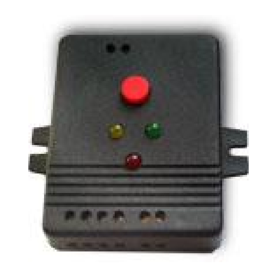
- Page 2 Eliminate the short-circuit. The yellow indicator shall be off on the module, the green one on. The detector will remain in standby mode of operation. Reset the status of the loop on the control panel. Figure 1 View of MUSH-DL...
- Page 3 Figure 2 Wiring diagram to security alarm panels...
Need help?
Do you have a question about the MUSH-DL and is the answer not in the manual?
Questions and answers