Table of Contents
Advertisement
WARNING
sales@agrotkindustrial.com
PRODUCT MANUAL
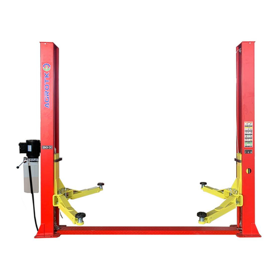
AG T - B 1 000 Tw o - P o st Au t o Li ft
This equipment can not be installed, operated or repaired without
reading instructions.
Electricity must be hooked up by certified electrician.
Do not use this equipment beyond its rated capacity.
Missing parts or questions on assembly?
Pleasecontact sales@agrotkindustrial.com
https://www.agrotkindustrial.com/
https://www.agrotkindustrial.com
Page 1 of 19
/
Advertisement
Table of Contents

Summary of Contents for AGT INDUSTRIAL AGT-B1000
- Page 1 PRODUCT MANUAL AG T - B 1 000 Tw o - P o st Au t o Li ft WARNING This equipment can not be installed, operated or repaired without reading instructions. Electricity must be hooked up by certified electrician. ...
-
Page 2: Table Of Contents
2 Post Base Plate Lift Installation & Operation & Maintenance Instructions Directory 1 - Lift Instructions ............................3 1. 1 Description ............................. 3 1.2 Technical Specifications ........................3 2 - Installation ............................... 4 2. 1 Preparation ............................4-5 2.2 Equipment Installation ........................5-8 3 - Check Before Start .......................... -
Page 3: Lift Instructions
1 - Equipment Description 1.1 Description This 2 Post Floor Plate Lift is an advanced car maintenance equipment, mainly used for automotive’ s repair and maintenance. 1 .2 Technical Specifications Lift Capacity 4500kg / 10000lbs Overall Height 2800mm/110.25” Overall Width 3500mm/137.8”... -
Page 4: Installation
Fig 1 Dimensions 2 - Installation This 2 Post Floor Plate Lift is the most common equipment for repairing cars. Its installation is not only related to the maintenance efficiency but also to personal safety of the maintenance technicians. Therefore, the installation must be completed by certified installers according to the User Manual, and in accordance with installation regulations. -
Page 5: Equipment Installation
Fig 2 Foundation Requirement 2.1.2 Tools Required Hammer, Socket Wrench Set, Hex Wrench Set, Adjustable Wrench, Screwdriver, Measuring Tape( 1 6’+), Long-Nose Plier, Circlip Pliers, Electric Rotary Hammer, Drill(3/4”), Safety Glasses, Work Gloves, Safety Helmet, Forklift/ Crane or something similar. 2 .2 Equipment Installation 2.2.1 Install Columns Stand up the 2 columns ( the column with the power unit base plate is the main column and... - Page 6 2.2.3 Install Cables (2 Cables in total) Red & Blue color in this Fig are showing how to route the 2 cables ( Fig 4 ) Fig 4 Cable Routing Diagram 2.2.4 Install Hydraulic Hose (2 Hose in total) Connect the longer hose in between the 2 cylinders, connect the short hose in between the cylinder and the power unit.
- Page 7 Fig 5 Hydraulic Hose Diagram 2.2.5 Install BasePlate (Fig 6) Place the Baseplate inside the columns slots. ( No screws needed) Fig 6 Baseplate Installation Diagram 2.2.6 Install Power Unit Install power unit on the main column with M8 screws ( Fig 7 ) . Fig 7 Power Unit Installation Diagram 2.2.7 Install Anchor Bolts (Fig 8) 1.
- Page 8 package) if necessary. 5 . Tighten anchor bolts nuts in diagonal order (Foot Pounds of Torque: 90+, suggest to use hand wrench to tighten nuts.) Fig 8 Anchor Bolts Installation Diagram 2.2.8 Install Arms and Pulling Rod Install arms and pulling rod (Fig 9 and Fig 10). Page 8 of 19...
-
Page 9: Check Before Start
Fig 9 Arm Installation Diagram Fig 10 Pulling Rod Installation Diagram 3 - Check Before Start 3 . 1 Mechanical Installation Check 1. Check anchor bolts, nuts, fittings and etc have been installed properly. 2 . Check if all moving parts move freely. 3 . -
Page 10: Hydraulic System Testing
Fig 11 Power Unit Wiring Diagram (Voltage: 220V) 3 .3 Hydraulic System Testing 1 . Add about 2 . 5 gallons of hydraulic oil to the hydraulic fluid reservoir, AW3 2 during winter time( cold weather), and AW46 during summer time( hot weather). 2. -
Page 11: Load Test
Fig 12 Power Unit Diagram * * Important Information* * 7 Pressure Valve: Clockwise adjustment increases pressure to make the power unit to have more power, counterclockwise adjustment decreases pressure to make the power unit to have less power. 8 Hydraulic Fluid Flow Valve: Clockwise adjustment to speed up, counterclockwise adjustment to slow down. -
Page 12: Stopping
when it is raised to a certain height ( stop and check). * Danger* : Unlocked arms can cause vehicle fall off from the lift. 4.3 Stopping After raising to desired height, press the lower lever and the lift will automatically lower to a safe position, the safety lock will be engaged and the lift will be locked. -
Page 13: Risk Of Vehicle Falling From The Lift
Fig 14 Risk of vehicle falling off 5 .3 Risk of Vehicle Falling Off From The Lift Note that when positioning the vehicle on the lift, incorrect center of gravity of the vehicle can cause the vehicle falling off from the lift (Fig 14). Important Note: Make sure that the front and rear of the vehicle need to be balanced and the cables on both sides also need to be balanced. -
Page 14: Troubleshooting Guide
7 - Troubleshooting Guide Troubleshooting Guide Malfunction Possible reason Solution 1.Check the air switch. 1. Turn off or replace the air switch. 2.Check if the voltage is 2. User correct power supply. correct. The motor does 3. Replace the motor. 3.The motor burned. -
Page 15: Structure And Parts List
8 - Structure and Parts List 8 . 1 Equipment Assembling Diagram Name Column Carriage Power Unit Cylinder Cable Hydraulic Hose Baseplate Hydraulic Hose Hose Fitting Hose Fitting Chain Circlip Φ 2 5 Oil Free Bearing Chain Wheel Shaft Chain Wheel ixed haft Page 15 of 19... -
Page 16: Carriage Structure Diagram
8 2 Carria e Structure Dia ram Name Carriage Slide Block Lock Gear Unlocking Lever Unlocking Lever Compression Spring Door Guard Knob Mechanical Lock Washer Φ25 Washer Φ10 Cotter Pin Φ3X30 Bolt M8X25 B- Shape Circlip Safety Lock Release Cable Hexagon Socket Bolt M8X20 Nut M8... -
Page 17: Column Structure Diagram
8 3 Column Structure Dia ram Name Column Pulley Cover Oil Free Bearing Shaft Circlip Φ25 Flat Washer Φ10 Spring Washer Φ10 Outer Hexagonal Bolt M10 X35 Top Limiter Switch Bolt M5X10 Motor Base Plate Flat washer Φ10 Spring Washer Φ10 Hexagon Socket Bolt M10 X12 Outer hexagonal Bolt M8X20 Nut M8... -
Page 18: 3-Stage Arm
8. 4 3- stage arm Part# Name Inner arm of three stage arms DNLM-05-01-00 Middle arm of three stage arms DNLM-05-02-00 Outer arm of three stage arms DNLM-05-03-00 Inside hex bolt M1 0 X2 0 IH001020 Moon gear DBLM-00-25 IH000810 Inside hex bolt M8 X1 0 Sleeve of one stage screwed pad DBLM-00-26... -
Page 19: 2-Stage Arm
8.5 2-stage arm Part# Name Inner arm of two stage arms DBLM-06-01-00 Outer arm of two stage arms DBLM-06-02-00 Moon gear DBLM-00-25 Inside hex bolt M1 0 X2 0 IH001020 Inside hex bolt M1 0 X1 0 IH000820 Sleeve of one stage screwed pad DBLM-00-26 Extension DBLM-00-27...
Need help?
Do you have a question about the AGT-B1000 and is the answer not in the manual?
Questions and answers
How I can find the part for that lift