
Related Manuals for MOUNT PRO PR5001


Summary of Contents for MOUNT PRO PR5001
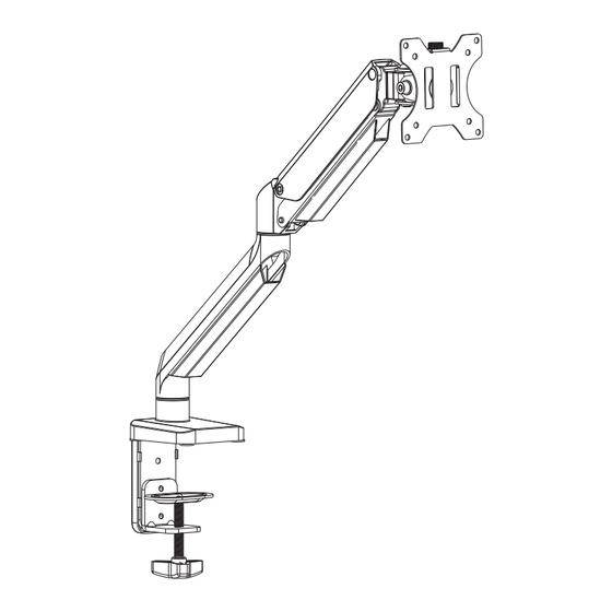
- Page 1 Single Monitor Counterbalance Desk Mount Instruction Manual PR5001 1.5~8kg (3.3~17.6lbs) RATED If you have any questions , please contact us via: help@ohopeglobal.com V1.0...
- Page 2 WARNING! If you do not understand these instructions or have doubts about the safety of the installation, assembly or use of this product, contact Customer Service via help@ohopeglobal.com. Before starting assembly, verify all parts are included and undamaged. Improper installation may cause damage or serious injury.
-
Page 3: Package Contents
PACKAGE CONTENTS Components A (x1) Monitor Stand B (x1) C (x1) D (x1) E (x1) F (x1) Clamp Base Clamp Base Support Cover Long Screw VESA Plate Support H (x1) I (x1) J (x5) K (x1) G (x1) Support Plate Security Screw Bolts Wingnut... - Page 4 STEP 1 Choose a mounting option OPTION A: Clamp Installation Install clamp base support (C) onto base of monitor stand (A) with bolts (J) using provided 4mm Allen wrench (M). Apply pads (L) to bottom of base to prevent table top from being scratched.
- Page 5 Adjust the Mount to the Desktop Adjust the Mount to the Desktop Thickness 50-85mm Thickness 10-55mm Secure clamp (D) to lower two holes with Secure clamp (D) to upper two holes with bolts (J) using 4mm Allen wrench (M) for bolts (J) using 4mm Allen wrench (M) for desks with a thickness of 50-85mm.
- Page 6 STEP 1 (Continued) OPTION B: Grommet Base Installation Slide long screw (F) through the top of the grommet base support (G) and install on base of monitor stand (A) with bolts (J) using 4mm Allen wrench (M). Apply pads (L) to bottom of base. Position stand on desk with long screw through hole, and secure by using the support plate (H) and Wingnut (K).
- Page 7 STEP 2 Attach the monitors to the arm OPTION A:Flat Back Monitor Attach the VESA plate (B) to back of monitor and secure with screws (M-A) or (M-C) with washers (M-E) using 6mm Allen Wrench(N). Avoid excessive tightening screws damage the monitor.
- Page 8 Slide the monitor onto the head of swivel arm, install the security screw (I). Make sure the security screw is installed before you rotate the monitor. Refer to below illustrations to adjust tilting angle of your monitor. Note: Fasten/loosen the tilting bolt as needed per arrow direction (+/-) shown in above diagram.
-
Page 9: Step 3 Adjust The Tension
STEP 3 Adjust the tension For proper functioning of this mount, depending on di erent weight of monitor you might need to adjust tension in gas spring (A) using 6 mm allen key (N). monitor stand After being attached to the arm, the monitor falls down and can not stay at the desired height by itself. -
Page 10: Step 4 Cable Management
STEP 4 Cable Management For both bottom and upper portion of the spring arm, just slide the cable cover up and away from the spring arm, do not need to take much effort to pull the ends of the cable cover away from the spring arm. - Page 11 Adjust as Desired Allen wrench(M,N) can be stored in Base Support Cover(E) for next time using. Note: When tilted, if the monitor sags or does not stay, please fasten the tilting bolt on the mount until the monitor can be held at any angle as needed. ±90°...
- Page 12 CAUTION AND MAINTENANCE: • Never allow children to climb, stand, hang, or play on any part of monitor or stand. • This product is intended for indoor use only. Using this product outdoors could lead to product failure and personal injury. •...
Need help?
Do you have a question about the PR5001 and is the answer not in the manual?
Questions and answers