Table of Contents
Advertisement
Quick Links
Instructions
THERM-O-FLOW
EC-20/40 Timer
For use with THERM-O-FLOW Hot Melt Tanks
Model 118051
EC-20 two event timer for 115 VAC and 230 VAC
Model 118052
EC-40 four event timer for 115 VAC and 230 VAC
Read warnings and instructions.
See page 2 for table of contents.
Graco Inc. P.O. Box 1441 Minneapolis, MN 55440-1441
Copyright 2004, Graco Inc. is registered to I.S. EN ISO 9001
®
310814 Rev.A
Advertisement
Table of Contents

Related Manuals for Graco THERM-O-FLOW EC-20

Summary of Contents for Graco THERM-O-FLOW EC-20
- Page 1 EC-40 four event timer for 115 VAC and 230 VAC Read warnings and instructions. See page 2 for table of contents. Graco Inc. P.O. Box 1441 Minneapolis, MN 55440-1441 Copyright 2004, Graco Inc. is registered to I.S. EN ISO 9001...
-
Page 2: Table Of Contents
Setup ........6 Graco Information ......14 Troubleshooting . -
Page 3: Warnings
Do not alter or modify equipment. • For professional use only. • Use equipment only for its intended purpose. Call your Graco distributor for information. • Route hoses and cables away from traffic areas, sharp edges, moving parts, and hot surfaces. •... -
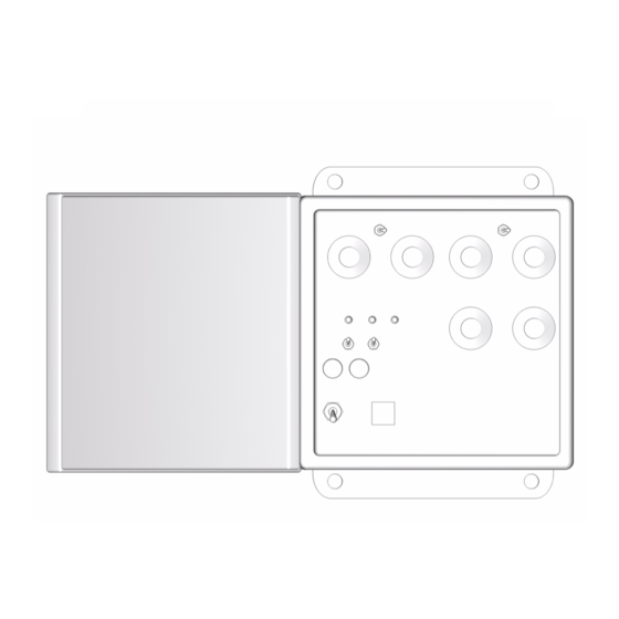
Page 4: Installation
Installation Installation EC-20 Model 118051 EC-40 Model 118052 . 1: Typical Installation Key: Channel Two On/Off Switch Fuses EC-40 (F1 and F2) Channel One On/Off Switch Channel Two Stitch/Seal Switch Delay Switch Line Voltage Select Pattern Switch Stitch/Seal Length Dial Pattern Delay Dial Stitch/Seal Gap Dial Pattern Length Dial... - Page 5 Installation Control cords used Depending on your system setup, you will need the appropriate control cord. Use the chart below, to order the appropriate cord for the EC-20/40 timers Part number Used with Plugs into Applicators AC or DC 118242 EC-20 or EC-40 T5 or T7 1 EG, AG, or Com-pak...
-
Page 6: Setup
Setup Setup EC-20/40 WARNING From the hot melt tank, remove cover on auxiliary connector. To avoid electrical shock, disconnect all power from the timer. See Warnings, page 3. Using the appropriate control cord, plug in auxiliary Connecting Timer cable to the tank auxiliary connector. Properly line up pins. - Page 7 Setup Setting timers and controllers Start up and adjust hot melt tank settings. See All zone heating indicators must flash green before appropriate hot melt tank manual. pump can operate. T5-see manual 309831 T7-see manual 309832 T18-see manual 309833 Setting both timers will take some adjusting until you get the appropriate dispensing pattern.
- Page 8 Setup Setting EC-40 See F . 4.The EC-40 is a four event timer. Event one Set line voltage switch (Q) to appropriate voltage. and three are the delay or periods of time when the applicator is not dispensing. Event two and four are pat- tern length or periods of time when the applicator is dis- pensing.
- Page 9 Setup Setting stitching on EC-40 See F . 4, page 8. The EC-40 has the capability to Adjust the stitch length dial (R). Dial setting “0” is stitch or seal. Stitching is repetitive dispenses of mate- shortest duration, dial setting “10” longest duration. rial.
-
Page 10: Troubleshooting
Troubleshooting Troubleshooting Problem Cause Solution No pilot light Not properly connected to line power. Check F1 Pilot light is dim. Aux circuit does not Line voltage switch not properly set Check line voltage switch for proper work. 24 VDC outputs are 12 VDC setting. -
Page 11: Repair
Repair Repair Replacing fuses WARNING Replace timer fuses (H) or (N) by pulling out old fuse and inserting new fuses from fuse kit 118182. See F 1, page 4. To avoid electrical shock, disconnect all power from timer. See Warnings, page 3. . -
Page 12: Dimensions
Replacement Parts Replacement Parts Part No. Description Qty. 189930 LABLES, warning 118182 REPAIR KIT, fuses and motor con- trol board 118261 RELAY, 15 amp Dimensions 4 in. (101.6 mm) 0.5 in. (12.7 mm) diameter 7.5 in. (190.5 mm) 6.75 in. (171.5 mm) 6 in. - Page 13 Technical Data 310814A...
-
Page 14: Graco Standard Warranty
With the exception of any special, extended, or limited warranty published by Graco, Graco will, for a period of twelve months from the date of sale, repair or replace any part of the equipment determined by Graco to be defective.
Need help?
Do you have a question about the THERM-O-FLOW EC-20 and is the answer not in the manual?
Questions and answers