Table of Contents
Advertisement
Quick Links
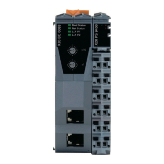
EtherNet/IP インターフェイスユニット メインモジュール /
EtherNet/IP Interface unit Main module
MG70-EI
お買い上げいただき、ありがとうございます。
ご使用の前に、この取扱説明書を必ずお読みください。
ご使用に際しては、この取扱説明書どおりお使いください。
お読みになった後は、後日お役に立つこともございますので、必ず保管してください。
Read all the instructions in the manual carefully before use and strictly follow them.
Keep the manual for future references.
取扱説明書 / Instruction Manual
Advertisement
Chapters
Table of Contents

Related Manuals for Magnescale MG70-EI

Summary of Contents for Magnescale MG70-EI
- Page 1 EtherNet/IP インターフェイスユニット メインモジュール / EtherNet/IP Interface unit Main module MG70-EI お買い上げいただき、ありがとうございます。 ご使用の前に、この取扱説明書を必ずお読みください。 ご使用に際しては、この取扱説明書どおりお使いください。 お読みになった後は、後日お役に立つこともございますので、必ず保管してください。 Read all the instructions in the manual carefully before use and strictly follow them. Keep the manual for future references. 取扱説明書 / Instruction Manual...
- Page 2 SAFETY PRECAUTIONS PRECAUTIONS FOR CORRECT USE Connect cables to the unit property as shown in the Definition of Precautionary Information instruction manual. Not doing so may result in a failure of the unit. Indicates a potentially hazardous situation Caution which, if not avoided, may result in minor or Do not install the unit in the following places: moderate injury, or property damage.
-
Page 3: Table Of Contents
2.1. Equipment used ......................3 2.2. Equipment connection configuration ................4 3. Downloading the necessary files ..................5 4. MG70-EI (X20BC0088) main unit settings ................. 6 4.1. IP address settings ......................6 4.2. Downloading the configuration file .................. 9 5. Operations to be performed using Logix Designer ............10 5.1. -
Page 4: Introduction
1. Introduction The MG70-EI is a EtherNet/IP Interface unit Main module created by Bernecker + Rainer Industrie Elektronik (hereafter, B&R) and sold by Magnescale Co., Ltd. This manual describes the operation necessary in the Rockwell Automation development environment (Logix Designer) when introducing the MG70-EI, MG71-CM and digital gauges. -
Page 5: Basic Information
EtherNet/IP uses the terms “scanner” and “adapter” in place of “master” and “slave”, respectively. 2.1. Equipment used This section shows the adapter (MG70-EI) side components used in the descriptions in this manual, and the connection configuration of the various equipment. Table 2-1 List of equipment used on the adapter side Magnescale B&R... -
Page 6: Equipment Connection Configuration
X20DC11A6 Fig 2-2 Adapter side connection diagram The Ethernet cable used to connect the scanner side and the MG70-EI should be shielded in accordance with the operating environment. Use a shielded RJ45 (8P8C) connector as the MG70-EI side connector. 4 (E) -
Page 7: Downloading The Necessary Files
→ “Digital Gauge” → “MG70/71” → “Software” Click “Download” of the MG70-EI corresponding to the number of MG71-CM to be used, and download the file. Save the downloaded file in the appropriate location, and extract the file using file extraction software. -
Page 8: Mg70-Ei (X20Bc0088) Main Unit Settings
4. MG70-EI (X20BC0088) main unit settings 4.1. IP address settings The main unit IP address settings are made using the X20BC0088 Web server function. Check the following items before making the settings. ・The number of nodes switch of the X20BC0088 should be set to “0xFF” before supplying power to the X20BC0088. - Page 9 Select “Advanced” from the left menu, and select “Set Network Parameters” from the expanded menu. Fig 4-2 X20BC0088 -- IP address setting -- No.2 Click “Login”. Set “Username” to “admin” and “Password” to “X20BC0088” , and click “Login”. * The username and password can be changed from “Advanced” after login. Click “Reset Form”.
- Page 10 10. Enter the IP address set in step 7 above in the URL field of the Web browser, and check that the X20BC0088 Web server can be accessed. Also check that the “IP address” and other values of “Network Settings” on the “Adapter Status”...
-
Page 11: Downloading The Configuration File
4.2. Downloading the configuration file Access the X20BC0088 Web server from the Web browser. * In the example in this manual, “192.168.0.100” is accessed. Select “Configuration” from the left menu. Fig 4-5 X20BC0088 -- Downloading the configuration file -- No.1 Click “Login”... -
Page 12: Operations To Be Performed Using Logix Designer
5. Operations to be performed using Logix Designer The description in this section uses the Rockwell Automation “Logix Designer V27.00” as the development environment. This description also uses the Rockwell Automation (Allen-Bradley) 1769-L18ER-BB1B (CPU, EtherNet/IP scanner) as the network element. The network is constructed locally, and the IP address of each element is set as a static IP address as shown below. -
Page 13: Reflection To An Existing Project
5.2. Reflection to an existing project Start up two Logix Designers, open the project created in section 5.1 above in one Logix Designer, and open an existing project (or a new project) in the other Logix Designer. * This manual describes the opening of a new project. Select “ETHERNET-MODULE ST1”... - Page 14 With the same operation, move “CopyInputData” and “CopyOutputData” under “Tasks” to the existing project side. Likewise, move “ST1_INPUT” and “ST1_OUTPUT” under “Data Types” to the existing project side. Fig. 5-4 Logix Designer -- Reflection to an existing project -- No.2 Open “Controller Tags”...
- Page 15 Select the “Program Schedule” tab in the Properties window, and arrange the “Scheduled” items in order of “CopyInputData”, “MainProgram”, “CopyOutputData”. * Arrange the items so that the program that will use the MG70-EI I/O data is located between “CopyInputData” and “CopyOutputData”. When finished, click “OK”.
- Page 16 Open the “CopyInputData” program and delete the “ADD” command. Delete Fig. 5-8 Logix Designer -- Reflection to an existing project -- No.6 Open the “CopyOutputData” program, and delete the “ADD” command. Delete Fig. 5-9 Logix Designer -- Reflection to an existing project -- No.7 This completes reflection to an existing project.
-
Page 17: Ip Address Settings
5.3. IP address settings Start up Logix Designer and open the existing project used in the reflection task in section 5.2 above. Right-click the added “ETHERNET-MODULE ST1”, and select “Properties”. Fig. 5-10 Logix Designer -- IP address settings -- No.1 Select the “General”... -
Page 18: Reference) Creation Of Various Files By The User
To use a number of MG71-CM not available on the Magnescale website with the MG70-EI, or to change the I/O data to be used, use the B&R software FieldbusDESIGNER. 6.1. FieldbusDESIGNER introduction The description in this section assumes that the FieldbusDESIGNER version is V3.0.80.42. -
Page 19: License Registration
6.1.3. License registration If the FieldbusDESIGNER license has not yet been registered, follow the procedure below and register the license. ※The software can be used for a 30-day trial period in the unregistered condition. Once this trial period has passed, FieldbusDESIGNER cannot be used until license registration is performed. -
Page 20: Downloading The Necessary Files
Access the license registration page on the B&R website. (http://service.br-automation.com/softwareRegistration/bin/index.jsp) Enter the character string displayed in “System code (Sys-ID)” in the “System Code” field, and click “Register”. An offline activation code will be displayed. Make a note of this code. Return to the previous popup window, enter the activation code in the “License code (Sec-ID)”... - Page 21 A hardware upgrade file selection window will be displayed. Select the hardware upgrade file (AS3.0_HW_X20DC11A6.exe) saved in section 6.2 above. X20DC11A6 will be displayed in the hardware upgrade selection window. Make sure that the checkbox contains a check mark, and click “OK”. Check Fig 6-4 FieldbusDESIGNER -- Hardware upgrade -- No.3 The X20DC11A6 hardware upgrade process will start.
-
Page 22: New Project Creation
6.3.2. New project creation Start up FieldbusDESIGNER. Select “File” → “New Project…” from the menu. Enter appropriate values in “Name of the project” and “Path of the project” in the displayed popup window, and click “Next”. Name of the project Path of the project Description of the project Fig 6-6 FieldbusDESIGNER -- New project creation -- No.1... - Page 23 Select the bus module used to generate the configuration file. In this manual it is necessary to generate only X20BC0088 (EtherNet/IP), so this manual describes the process when selecting “EtherNet/IP CPU” and clicking “Next”. Fig 6-8 FieldbusDESIGNER -- New project creation -- No.3 A confirmation window will be displayed for the project to be created.
- Page 24 New projects can be created by performing the above procedure. Fig 6-10 FieldbusDESIGNER -- After creating a new project 22 (E)
-
Page 25: Build Project
6.3.3. Build project Right-click “EtherNet/IP” in “Physical View” of the left pane, and select “Open EtherNet/IP” from the displayed context menu. The new tab “PLC1.CPU [EtherNet/IP]” will open in the center pane. Fig 6-11 FieldbusDESIGNER -- Build project -- No.1 Right-click the “IF1 (EtherNet/IP)”... - Page 26 X20BC0088 and X20PS9400 will be added in the “Physical View” pane. X20BC0088 will also be added in the formerly blank location in the “PLC1.CPU [EtherNet/IP]” tab. Fig 6-14 FieldbusDESIGNER -- Build project -- No.4 Right-click X20BC0088 in the “Physical View” pane, and select “Open X2X Link” in the displayed context menu.
- Page 27 This manual describes the process when adding only one X20DC11A6 below X20BC0088. 10. To locate multiple MG70-EI (X20BC0088) on the same EtherNet/IP network, repeat steps 1 through 9 above. This manual describes the process when using only one MG70-EI (X20BC0088).
-
Page 28: Build
6.3.4. Build Select “Project” → “Build Configuration” from the menu. Fig 6-19 FieldbusDESIGNER -- Build -- No.1 After build is complete, check that an error is not output in the “Output” pane. Fig 6-20 FieldbusDESIGNER -- Build -- No.2 The files generated by build are located in the “Output” folder below the folder where the project file is located. - Page 29 容 ( 操作、保守など ) と異なる目的で本マニュアルを使用 することを禁止します。 The material contained in this manual consists of information that is the property of Magnescale Co., Ltd. and is intended solely for use by the purchasers of the equipment described in this manual. Magnescale Co., Ltd. expressly prohibits the duplication...
- Page 30 (or technology) may be restricted by the government in your country. Please make sure that end-use, end user and country of destination of this product do not violate your local government regulation. 〒 259-1146 神奈川県伊勢原市鈴川 45 45 Suzukawa, Isehara-shi, Kanagawa 259-1146, Japan MG70-EI 2016.11 2-A02-328-0A ©2016 Magnescale Co., Ltd.
- Page 31 ファイルを使用します。EDS ファイルを使用される ● 本製品は防爆構造になっていませんので、可燃性 To obtain the instruction manuals, download them 場合の取扱い方については、別途お問い合わせくだ ガスの雰囲気中では使用しないでください。火災 from the website of Magnescale Co., Ltd. or contact your さい。 の原因となることがあります。 nearest sales representative. ● 設置中や操作中に異常 ( 煙・音・匂いなど ) が発 Be sure to operate the product according to the 取扱説明書...
- Page 32 • Locations subject to temperatures or An L5K file or EDS (Electronic Data Sheet) file is needed to use the MG70-EI. These files can be Do not disassemble or modify the humidity outside the range specified in the downloaded by accessing the product information page ...
- Page 33 ● 本製品は防爆構造になっていませんので、可燃性 To obtain the instruction manuals, download them ガスの雰囲気中では使用しないでください。火災 from the website of Magnescale Co., Ltd. or contact your の原因となることがあります。 nearest sales representative. ● 設置中や操作中に異常 ( 煙・音・匂いなど ) が発 Be sure to operate the product according to the 生した場合、すぐに接続ケーブルを外して、サー...
- Page 34 Take all possible safety measures when mounting + Rainer Industrie Elektronik (hereafter, B&R) and sold Definition of Precautionary Information forms of noise by Magnescale Co., Ltd. the product and operating a mounted device. • Locations subject to strong electromagnetic Indicates a potentially When connecting and disconnecting a signal For the MG71-CM specifications, refer to the B&R product...
- Page 35 PROFINET RT インターフェイスユニット メインモジュール / PROFINET RT Interface unit Main module MG70-PN お買い上げいただき、ありがとうございます。 ご使用の前に、この取扱説明書を必ずお読みください。 ご使用に際しては、この取扱説明書どおりお使いください。 お読みになった後は、後日お役に立つこともございますので、必ず保管してください。 Read all the instructions in the manual carefully before use and strictly follow them. Keep the manual for future references. 取扱説明書 / Instruction Manual...
- Page 36 SAFETY PRECAUTIONS PRECAUTIONS FOR CORRECT USE Connect cables to the unit property as shown in the Definition of Precautionary Information instruction manual. Not doing so may result in a failure of the unit. Indicates a potentially hazardous situation Caution which, if not avoided, may result in minor or Do not install the unit in the following places: moderate injury, or property damage.
-
Page 37: Contents
Contents Contents ........................... 1 1. Introduction .......................... 2 2. Basic Information ........................ 3 2.1. Equipment used ......................3 2.2. Equipment connection configuration ................4 3. Downloading the necessary files ..................5 4. B&R: Operations to be performed using Automation Studio ......... 6 4.1. -
Page 38: Introduction
1. Introduction The MG70-PN is a PROFINET RT Interface unit Main module created by Bernecker + Rainer Industrie Elektronik (hereafter, B&R) and sold by Magnescale Co., Ltd. This manual describes the operation necessary in each company’s development environment (B&R: Automation Studio, Siemens: SIMATIC STEP 7) when introducing the MG70-PN and MG71-CM digital gauges. -
Page 39: Basic Information
2.1. Equipment used This section shows the slave (MG70-PN) side components used in the descriptions in this manual, and the connection configuration of the various equipment. Table 2-1 List of equipment used on the slave side Magnescale B&R Description Appearance Qty. -
Page 40: Equipment Connection Configuration
2.2. Equipment connection configuration MG70-PN X20BB80 Master side Ethernet cable (MG70-PN side: RJ45 connector) X20BC00E3 Digital Gauge DC24V X20PS9400 MG71-CM X20TB12 Blue Yellow Orange Gray Green Supplied cable Purple White X20BM11 X20TB12 X20DC11A6 Fig 2-1 Slave side connection diagram The Ethernet cable used to connect the master side and the MG70-PN should be shielded in accordance with the operating environment. -
Page 41: Downloading The Necessary Files
3. Downloading the necessary files Access the B&R website (http://www.br-automation.com/), and select: “Downloads” → “Product Groups: Networks and fieldbus modules” → “Networks and fieldbus modules: PROFINET” → “PROFINET: Bus controllers” → “Bus controllers: X20BC00E3” Download “Profinet Buscontroller GSD Package”. Save the downloaded file in the appropriate location, and extract the file using file extraction software. -
Page 42: B&R: Operations To Be Performed Using Automation Studio
4. B&R: Operations to be performed using Automation Studio The description in this section uses the B&R “Automation Studio V4.2.3.159” as the development environment. This description also uses the B&R X20CP3585(CPU), X20IF10E1-1 (PROFINET RT master as the network element. The network is constructed locally, and the IP address of each element is set as a static IP address as shown in the table below. - Page 43 The DTM catalog update will start. Wait until the update is complete. Fig 4-3 Automation Studio -- Importing the GSDML file -- No.3 The update is complete when the message “DTM catalog update successfully finished…” appears in the “Output” pane. Fig 4-4 Automation Studio -- Importing the GSDML file -- No.4 “X20BC00E3”...
-
Page 44: Setting The Ip Address And The Device Name
4.2. Setting the IP address and the device name Static IP address and device name settings must be made for both the main unit side and the project side. 4.2.1. Main unit side The main unit side and project side settings are both made by Automation Studio. Check the following items before making the settings. - Page 45 A new tab will open. After the tab opens, it appears as shown below. Check that “Navigation Area” is “Controller Network Settings”. The “Network Settings” displayed here are the settings for X20IF10E1-1. Fig 4-8 Automation Studio -- Setting the IP address and the device name (main unit side) -- No.3 Set “IP address”...
- Page 46 Click “Search Devices”. The active devices on the Ethernet device network that have check marks will be listed in “Devices Online”. Of the displayed devices, the device with “B&R PN Bus Controller” displayed as the “Device Type” is the X20BC00E3. * To reliably identify the X20BC00E3, check that the “MAC Address”...
- Page 47 At the default setting, the IP address is not set. Select “Set IP Address” tab, set “IP Address” and “Subnet mask” with “Use static IP Address” to the desired values (the values to be used with the actual network), and click “Set Address”. * In the example in this manual, “IP Address”...
-
Page 48: Project Side
4.2.2. Project side 1. Open “Device Configuration” of “Profinet (DTM)” under X20IF10E1-1, and select “Device Table” from “Navigation Area”. Of the displayed devices, the device with “Device” set to “X20BC00E3” is the X20BC00E3. Set “Name of station” to the value set in step 8 of section 4.2.1 above, and click “Apply”. -
Page 49: Configuration Setting For Mg71-Cm
4.3. Configuration setting for MG71-CM The X20BC00E3 that can be located in “Physical View” by the operation in section 4.1 above is the configuration up to the MG70-PN. The following task must be performed to set the configuration up to the MG71-CM part. Right-click X20BC00E3 in “Physical View”, and select “Device Configuration”... - Page 50 Select the addedd module, and select “X20DC11A6_C1”. * Note that “X20DC11A6_C1” is located at the bottom of the list. Fig 4-22 Automation Studio -- Configuration setting for MG71-CM -- No.4 To use the X20DC11A6 latch function or other functions, expand “X20DC11A6_C1”...
-
Page 51: Communication Settings
4.4. Communication settings In order to correctly acquire data, it is necessary to set only one of the combinations of master and slave settings to little-endian. If both are big-endian or both are little-endian, 4.4.1. Master side the MSB/LSB of the acquired data will be inverted. Open “Device Configuration”... -
Page 52: Siemens: Operations To Be Performed Using Simatic Step 7
5. Siemens: Operations to be performed using SIMATIC STEP 7 The description in this section uses the Siemens “SIMATIC STEP 7 Basic V13 SP1 Update 9” as the development environment. This description also uses the Siemens SIMATIC S7-1200 CPU1211C (CPU, PROFINET RT master) as the network element. - Page 53 Wait until GSDML file import is complete. When import is complete, a window will be displayed. Click “Close”. Fig. 5-3 SIMATIC STEP 7 -- Importing the GSDML file -- No.3 Fig. 5-4 SIMATIC STEP 7 -- Importing the GSDML file -- No.4 The hardware catalog will be automatically updated.
-
Page 54: Setting The Ip Address And The Device Name
5.2. Setting the IP address and the device name Static IP address and device name settings must be made for both the main unit side and the project side. 5.2.1. Main unit side Both the main unit and project side settings are made using SIMATIC STEP 7. Check the following items before making the settings. - Page 55 Select “Assign IP address” from the left menu of the opened page. At the factory default, the IP address is not set. Set “IP address” and “Subnet mask” to the desired values (the values to be used with the actual network), and click “Assign IP address”. * In the example in this manual, “IP address”...
- Page 56 Double-click “Update accessible devices” again, and check that a device with the device name and IP address set in steps 3 and 4 above has been added. Fig. 5-11 SIMATIC STEP 7 -- Setting the IP address and the device name (main unit side) -- No.5 This can also be checked by opening the Web browser, entering the set IP address in the URL field, and accessing the X20BC00E3 Web server.
-
Page 57: Project Side
5.2.2. Project side Add the X20BC00E3 as a new device, and open “Device Configuration”. Fig. 5-13 SIMATIC STEP 7 -- Setting the IP address and the device name (project side) -- No.1 Select X20BC00E3 in “Device view”, display the “Properties” tab, and select “Ethernet addresses”... -
Page 58: Configuration Setting For Mg71-Cm
5.3. Configuration setting for MG71-CM The X20BC00E3 that could be located in “Devices & networks” by the operation in section 5.1 above is the configuration up to the MG70-PN part. The following task must be performed to set the configuration up to the MG71-CM part. Open “Devices &... - Page 59 To use the X20DC11A6 latch or other functions, select “X20DC11A6_C1”, open the “Properties” tab, and open “Module parameters” from the left menu. The various parameters can be edited from this page. For a description of the parameters (registers), refer to the X20DC11A6 data sheet and the B&R “PROFINET RT User’s manual”.
-
Page 60: I/O Data Address Map
6. I/O Data address map This section describes the address map of the I/O data of each element (the elements defined in the GSDML file) used in this manual. For a description of each I/O data, refer to the X20PS9400 and X20DC11A6 data sheets or the B&R “PROFINET RT User’s manual”. -
Page 61: X20Dc11A6_C1
6.2. X20DC11A6_C1 Table 6-2 Address map of I/O data of X20PS9400 defined in GSDML file I/O data name Data Address type Group name Name ModuleOK Unsigned8 x + 0 PowerSupply01 Bool x + 1.0 Inputs_X20DC11A6_C1_a PowerSupply02 Bool x + 1.1 BW_Channel_A Bool x + 2.0... - Page 62 容 ( 操作、保守など ) と異なる目的で本マニュアルを使用 することを禁止します。 The material contained in this manual consists of information that is the property of Magnescale Co., Ltd. and is intended solely for use by the purchasers of the equipment described in this manual. Magnescale Co., Ltd. expressly prohibits the duplication...
- Page 63 (or technology) may be restricted by the government in your country. Please make sure that end-use, end user and country of destination of this product do not violate your local government regulation. 〒 259-1146 神奈川県伊勢原市鈴川 45 45 Suzukawa, Isehara-shi, Kanagawa 259-1146, Japan MG70-PN 2016.11 2-A02-326-0A ©2016 Magnescale Co., Ltd.
- Page 64 ● 本製品は防爆構造になっていませんので、可燃性 To obtain the instruction manuals, download them ガスの雰囲気中では使用しないでください。火災 from the website of Magnescale Co., Ltd. or contact your の原因となることがあります。 nearest sales representative. ● 設置中や操作中に異常 ( 煙・音・匂いなど ) が発 Be sure to operate the product according to the 生した場合、すぐに接続ケーブルを外して、サー...
- Page 65 Bernecker + Rainer Industrie Elektronik Definition of Precautionary Information forms of noise (hereat er, B&R) and sold by Magnescale Co., Ltd. the product and operating a mounted device. • Locations subject to strong electromagnetic Indicates a potentially When connecting and disconnecting a signal For the MG70-PN specifi...
- Page 66 ● 本製品は防爆構造になっていませんので、可燃性 To obtain the instruction manuals, download them ガスの雰囲気中では使用しないでください。火災 from the website of Magnescale Co., Ltd. or contact your の原因となることがあります。 nearest sales representative. ● 設置中や操作中に異常 ( 煙・音・匂いなど ) が発 Be sure to operate the product according to the 生した場合、すぐに接続ケーブルを外して、サー...
- Page 67 Take all possible safety measures when mounting + Rainer Industrie Elektronik (hereafter, B&R) and sold Definition of Precautionary Information forms of noise by Magnescale Co., Ltd. the product and operating a mounted device. • Locations subject to strong electromagnetic Indicates a potentially When connecting and disconnecting a signal For the MG71-CM specifications, refer to the B&R product...
Need help?
Do you have a question about the MG70-EI and is the answer not in the manual?
Questions and answers