Table of Contents
Advertisement
Quick Links
Advertisement
Table of Contents

Summary of Contents for AstroLink 4 micro
- Page 1 AstroLink 4 micro - astrojolo.com AstroLink 4 micro astrojolo.com 2023 WARNING! Do not connect or disconnect the stepper motor when the power is on. It may damage the stepper motor controller. Before changing the stepper motor type make sure the stepper holding current is set to 0%.
-
Page 2: Main Features
● user-defined alerts for voltages, current, energy, and temperature changes conditions ● programmable overcurrent and overvoltage protection ● dedicated AstroLink 4 panel software, ASCOM drivers available (Focuser, Switch, Observing Conditions, Safety Monitor), INDI driver available Technical data ●... -
Page 3: Device Overview
PC, USB hub, or other device powered with 12V. Sensors AstroLink 4 micro has two equivalent sensor inputs, so you can plug any available sensor into any socket and it will be recognized and properly assigned. Connecting more than one sensor (additional sky temperature and/or sky brightness) requires an additional sensor signal splitter. -
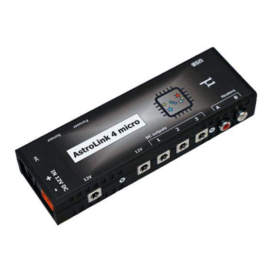
Page 4: External View
AstroLink 4 micro - astrojolo.com External view 1. permanent 12V DC output (dedicated for Y-3184 USB 3.0 hub) 2. permanent 12V DC output 3. switchable 12V DC outputs 4. 0-100% regulated heaters outputs 5. USB 2.0 input 6. firmware update button 7. - Page 5 AstroLink 4 micro - astrojolo.com There are four M3 threaded holes in the AstroLink 4 micro device bottom. These holes can be used to attach mounting plates or brackets to the device. Holes separation is 80x20mm. WARNING! Mounting screws cannot go deeper than 5mm to the AstroLink 4 micro enclosure.
- Page 6 AstroLink 4 micro is designed to work together with USB3.0 hub model Y-3184. The external dimensions of this 7 port USB hub and AstroLink 4 micro are the same, and the power and USB receptacles are aligned, so the hub and AstroLink 4 micro can be stacked into one device.
-
Page 7: Status Bar
AstroLink 4 micro - astrojolo.com Software panel overview AstroLink 4 micro panel contains several control sections. Most of the area is occupied by different controller sections, which will be described later on. Below the control section, several other controls are available. - Page 8 (like focuser positions, flat images exposure time, etc.). Its content is saved dynamically. Charts button opens an additional window with AstroLink charts. See the AstroLink charts section for details. Logo icon After clicking on the logo icon a small information window will pop up. It contains information about firmware and software versions.
-
Page 9: Connection Status
AstroLink 4 micro - astrojolo.com There are two more tabs available for the ASCOM driver. There you can adjust sky temperature cloud coverage mapping points that correspond to clear sky and maximum cloud coverage, and set names for DC and PWM outputs that will be visible in ASCOM Switch client software. - Page 10 Step size [um] - this value is stored in the driver and can be provided to any 3rd party software when requested. It is not used internally in AstroLink. Reversed - you can check this box when selecting the proper behavior of the focuser, so decreasing the...
- Page 11 This compensation is applied only when the motor is controlled with the AstroLink panel's button. When you use 3rd party software for focusing (FocusMax, MaxIm DL, and others) use this software for backlash compensation! Display motor graphics –...
- Page 12 AstroLink 4 micro - astrojolo.com temperature will change from the initial value. So if you put here 35 and the temperature will drop 2C, then the focuser will move 70 steps (outwards). This value usually must be determined practically, so you can note focuser positions over long night sessions together with corresponding...
- Page 13 AstroLink 4 micro - astrojolo.com PWM section PWM output value can be set between 0 and 100%. HEAT option controls value automatically based on current relative humidity. The AUTO option controls value automatically to keep Sensor #2 at a given temperature.
- Page 14 AstroLink 4 micro - astrojolo.com with increased measured value (REVERSED) The last tab is Frequency. Here there is only one select box where you can change the frequency of PWM output. It is usually the best approach to select the highest 31kHz frequency - this frequency is not audible by humans and also requires low-value LC filtering elements if you want to use it.
- Page 15 AstroLink 4 micro - astrojolo.com Sensors section Sensors and PWM sections are separate ones, although they work together to provide some combined functionalities. The sensors section contains four read-only fields that labels may be changed. The temperature/humidity sensors enclosures are numbered, and the sensor marked with the character “2” will be displayed in the #2 column in the panel.
- Page 16 Coefficient parameter. Offset – the difference between the AstroLink sensor reading and reference sensor reading Coefficient – second parameter that controls sensor calibration Reset sensor –...
- Page 17 AstroLink 4 micro - astrojolo.com 12V outputs section The second section is called the 12V output. Here we have three check-boxes that control DC outputs where you can connect supply voltage to peripheral devices like mounts, cameras, or filter wheels. Lock outs check-box can be checked and then the three boxes above will be locked (not clickable).
- Page 18 AstroLink 4 micro - astrojolo.com AstroLink charts AstroLink charts are the tool that allows you to monitor the following data that is collected by the AstroLink device: ● temperature, humidity, and dewpoint measured by connected sensors ● sky temperature and the difference between sky and ambient temperature (if the sky temperature sensor is connected) ●...
- Page 19 Collect data to file - this checkbox indicates if data is saved to the file. This is checked on by default, and data files are saved in the My Documents/AstroLink folder. Saved files may be later imported for example to an Excel sheet and processed ●...
-
Page 20: Overvoltage Settings
Overcurrent settings This preset should be adjusted to the receivers that we power from AstroLink. If we have a mount that drains 2A when doing GoTo, a camera that drains 2.5A at maximum cooling power, and a dew cap heater that consumes 1.5A, then the maximum current will be 6A. -
Page 21: Temperature Compensation
AstroLink 4 micro - astrojolo.com Temperature compensation Temperature compensation in AstroLink 4 micro is implemented linearly. So there is only one parameter that describes how temperature affects the focus point. It is not a perfect approach, however, its accuracy is good enough for most amateur setups. - Page 22 Auto compensation threshold described before You can save the script to the file with a VBS extension (astrolink-compensate.vbs for example), so it can be executed. Of course, there is little point in running this script manually. But you can point to that script in your acquisition software (like MaxIm DL, N.I.N.A, or Sequence Generator Pro), so that script can be executed after...
- Page 23 There you can check the current compensation coefficient, enter a new value, and save data to the device. Data points in the table are persisted in the file, so they will be available when you close and open the AstroLink panel again.
- Page 24 AstroLink 4 micro - astrojolo.com Data points quality It is recommended to collect data points in a reasonably wide range of temperatures. If data points cover a temperature range of 1 or 2 degrees, then the compensation coefficient may not be accurate. It is much better to have a temperature range of 5 or 10 degrees covered.
- Page 25 AstroLink 4 micro - astrojolo.com If the collected data points make the shape of a curve that crosses the calculated compensation line, it indicates that your setup focus point does not change linearly in the temperature range you choose. But you may still use compensation with a different value for different temperature ranges.
-
Page 26: Ground Loops
In this scenario, a negative voltage is supplied to the camera also in two ways. The first one is the main power cable between the camera and AstroLink. The second loop is from 5V output in AstroLink to the USB hub and then with the USB cable to the camera. - Page 27 = switch.SetSwitch(1, true) result = switch.SetSwitchValue(3, 30) result = switch.SetSwitchValue(4, 18) switch.Connected = false The script needs to be put into the file with VBS extension (for example astrolink-script.vbs) and then it can be started just by double click.
-
Page 28: Troubleshooting
● usually, you can just reconnect to the device ● if there is no AstroLink COM port in the system you need to plug out and plug in the USB cable or scan Windows Device Manager for new devices ●... - Page 29 Verify if you need holding torque at all. If you use some gearbox, then it may not be necessary. The sensor is not recognized - no value is read Disconnect the device, turn off the power, plug out and plug in the sensor and reconnect the power and AstroLink panel...
- Page 30 AstroLink 4 micro - astrojolo.com The AstroLink panel does not start When you play with AstroLink settings and connect the AstroLink device to different computers it may happen and you need to delete the local computer AstroLink settings folder. You need to 1.
- Page 31 AstroLink 4 micro - astrojolo.com Connections Power input Focusing motor and sensors connectors Focuser - RJ12 socket Sensor - RJ9 socket 1,2 - 12V DC 1 - GND 3,4 - COIL A 2 - SDA 5,6 - COIL B 3 - SCL 4 - 5V DC PWM outputs are regular RCA receptacles, tip positive.
-
Page 32: Third Party Software
ASCOM Observing Conditions can be connected to the ASTROJOLO Observing Conditions interface (SGPro, N.I.N.A.) In the image below – AstroLink 4 micro is connected to the panel software, focuser, and switch are connected to Maxim and N.I.N.A software at the same time. -
Page 33: Software And Firmware Update
Please read the release notes for details. When you notice that the AstroLink Local Server driver was not updated properly after installation, you need to perform the following steps: uninstall it again, remove manually folder C:\Program Files (x86)\Common Files\ASCOM\Focuser\AstroLink (or C:\Program Files\Common Files\ASCOM\Focuser\AstroLink in 32 bit systems) and all its content, and install local server driver one more time. - Page 34 AstroLink log files AstroLink device does not beep after connecting to the power supply AstroLink device is not recognized by the system after connecting to the computer - no COM port is visible Connection was lost The stepper motor vibrates but does not rotate...
- Page 35 The sensor is not recognized - no value is read Some fields in AstroLink panel software are red and there is a window system sound and the device beeps 23 The stepper motor does not rotate after clicking the plus or minus button and one beep is heard...
Need help?
Do you have a question about the 4 micro and is the answer not in the manual?
Questions and answers