Advertisement
ADVANCED MODERN TECHNOLOGIES CORPORATION
®
WATER CONSERVATION THROUGH INNOVATION
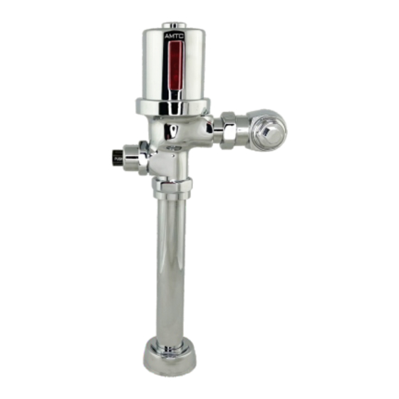
Water Closet Flushometer
for 1-1/2" Top Spud
Models:
AEF-802-CT-11 (HET)
AEF-802-CT-12 (HET)
AEF-802DF-CT-16 (HET)
AEF-802-CT-16 (LC)
AEF-802-CT-35
PRIOR TO INSTALLATION
PLEASE READ THIS MANUAL ENTIRELY TO INSURE PROPER PRODUCT INSTALLATION AND OPERATION. IF
YOU HAVE ANY QUESTIONS OR REQUIRE FURTHER ASSISTANCE PLEASE CONTACT YOUR LOCAL AMTC
REPRESENTATIVE OR CALL AMTC TECHNICAL SUPPORT AT 1-800-874-7822.
Before you install the flushometer, make sure that the items listed below are installed.
•
Fixture
•
Drain Line
•
Water Supply Line
IMPORTANT:
•
ALL PLUMBING SHOULD BE INSTALLED IN ACCORDANCE WITH APPLICABLE CODES AND
REGULATIONS. ONCE YOU INSTALL A SPECIFIC MODEL, I T CANNOT BE ADJUSTED UP OR DOWN
•
WATER SUPPLY LINES MUST BE SIZED TO PROVIDE AN ADEQUATE VOLUME OF WATER FOR EACH
FIXTURE
•
FLUSH ALL WATER LINES PRIOR TO M AKING CONNECTIONS
AMTC's flushometers are designed to operate with 10 to 100 psi (69 to 689 kPa) of water pressure. THE MINIMUM
PRESSURE REQUIRED TO THE VALVE IS DETERMINED BY THE TYPE OF FIXTURE SELECTED. Consult fixture
manufacturer for minimum pressure requirements. Most High Efficiency (HET) and Low Consumption (LC) water closets
(toilets) require a minimum flowing pressure of 25 psi (172 kPa).
ROUGH-INS
Rough-In for Water Closet (Toilet) Models
4.75"
2.25" MIN.
(121mm)
(57mm)
16.75"
PUSH
(426mm)
C/L OF
C/L OF
FIXTURE
FIXTURE
SPUD
SPUD
WHEN MOUNTED ON AN ADA ACCESSIBLE BOWL, THE ROUGH-IN TO THE SUPPLY INLET SHOULD
BE NO HIGHER THAN 37-1/2" OR THE SIDE PUSH BUTTON WILL EXCEED MAX. HEIGHT ALLOWANCES UNDER
ADA GUIDELINES. CHECK YOUR LOCAL ADA REQUIREMENTS AS THEY MAY VARY.
Owner's Manual for AEF-802 Series HYBRIDFLUSH
Exposed Water Closet (Toilet) and Urinal Flushometers
1" I.P.S.
PUSH
5.25"
SUPPLY
(134mm)
(DN 25mm)
C/L OF
SUPPLY
11.5"
(292mm)
!!! IMPORTANT !!!
!!! IMPORTANT !!!
Rough-In for Urinal Models
2.25" MIN.
(57mm)
16.75"
(426mm)
C/L OF
FIXTURE
SPUD
Urinal Flushometer
for 3/4" Top Spud
Models:
AEF-802-CU-18 (HEU)
AEF-802-CU-05 (HEU)
AEF-802-CU-10 (LC)
AEF-802-CU-15
4.75"
(121mm)
3/4" I.P.S.
5.25"
SUPPLY
(134mm)
(DN 20mm)
PUSH
C/L OF
SUPPLY
11.5"
(292mm)
C/L OF
FIXTURE
SPUD
®
PUSH
Advertisement
Table of Contents

Summary of Contents for AMTC HYBRIDFLUSH AEF-802 Series
- Page 1 FLUSH ALL WATER LINES PRIOR TO M AKING CONNECTIONS AMTC's flushometers are designed to operate with 10 to 100 psi (69 to 689 kPa) of water pressure. THE MINIMUM PRESSURE REQUIRED TO THE VALVE IS DETERMINED BY THE TYPE OF FIXTURE SELECTED. Consult fixture manufacturer for minimum pressure requirements.
- Page 2 TOOLS REQUIRED FOR INSTALLATION • Flat Head Screwdriver • Pliers • Smooth Jawed Spud Wrench !!! IMPORTANT !!! DO NOT USE TOOTHED TOOLS TO INSTALL OR SERVICE THE PRODUCT AS IT MAY DAMAGE THE CHROME . !!! IMPORTANT !!! NEVER OPEN CONTROL STOP WHERE THE WATER FLOW EXCEEDS THE FLOW CAPABILITY OF THE FIXTURE. IN THE EVENT OF A FAILURE, THE FIXTURE MUST BE ABLE TO ACCOMMODATE A CONTINUOUS FLOW FROM THE VALVE.
- Page 3 GASKET NOTE: VACUUM BREAKER Maximum adjustment of the AMTC Adjustable Tailpiece is 1/2" (13 mm) In or Out from the standard 4-3/4" (121 COUPLING mm) (center line of Flushometer to center line of Control Stop). If rough-in measurement exceeds 5-1/4"...
- Page 4 WARNING: PLEASE READ BEFORE INSTALLING THE ELECTRONIC OPERATOR PLEASE READ THE IMPORTANT NOTES BELOW BEFORE INSTALLING THE BATTERIES INTO THE UNIT! PLEASE DO THE FOLLOWING BEFORE INSTALLING THE BATTERIES: 1. DRY YOUR HANDS BEFORE HANDLING THE BATTERIES. 2. MAKE SURE BATTERY CONTACT AREA IS COMPLETELY DRY AFTER INSTALLING THE LOCKING RING AND BEFORE INSTALLING THE BATTERIES! 3.
- Page 5 Thank you for purchasing the HYBRIDFLUSH automatic/manual flush valve system by Advanced Modern Technologies Corporation (AMTC). The patented “hybrid” design gives the user the ability to flush the fixture by touch-free infrared sensor activation or by a push button located on the top of the unit. A “true mechanical” back-up flush option by way of the side push button allows the fixture to flush manually even when the battery power is drained or absent.
- Page 6 SENSOR DISTANCE ADJUSTMENT USING TOP PUSH BUTTON Directions: Electronic Push Button 1. Press (unit will flush once) and hold down Electronic Push Button until you see a blinking red LED in sensor window. Red LED Release Electronic Push Button, wait one second, then press and immediately release Electronic Push Button to put unit into sensor distance setup mode.
-
Page 7: Battery Replacement
SENSOR ANGLE ADJUSTMENT Top Cover Screw Directions: 1. Using Allen Wrench provided loosen the Top Cover Screw and remove Top Cover. 2. Using a small screwdriver slowly turn the Angle Adjustment Screw clockwise to increase the sensor angle downward or counterclockwise to decrease the angle. -
Page 8: Care And Maintenance
Locking ring does not fit valve body correctly Check that threading on valve body is not damaged. Replace valve body if necessary. Locking ring may be damaged. Replace the locking ring if necessary. Please call AMTC Technical Support at 1-800-874-7822 if further assistance is needed. -
Page 9: Repair Kits
PARTS LIST (REFER TO FIGURE A) Ref. No. Part No. Description FIGURE A Top Cover TC802 Installation Tools Strap Locking Ring for AMTC Flush Body LR802-S Wrench Electronic Module Assembly EMA802 Allen Wrench AA Batteries (Set of 4) AABAT Screwdriver... - Page 10 LIMITED WARRANTY AMTC WARRANTS ITS PRODUCTS TO BE FREE OF DEFECTS IN MATERIAL AND WORKMANSHIP FOR A PERIOD OF FIVE (5) YEARS FROM DATE OF PURCHASE, WHEN PROPERLY INSTALLED AND UNDER NORMAL USE AND SERVICE. THESE PROVISIONS DO NOT INCLUDE THE BATTERIES SHIPPED WITH THE PRODUCTS.
Need help?
Do you have a question about the HYBRIDFLUSH AEF-802 Series and is the answer not in the manual?
Questions and answers