Table of Contents
Advertisement
Quick Links
Advertisement
Table of Contents

Summary of Contents for ExcelPool Products 5120
- Page 1 INSTALLATION AND USER’S GUIDE VARIABLE SPEED PUMP 5120/5122...
- Page 2 IMPORTANT PUMP WARNING AND SAFETY INSTRUCTIONS IMPORTANT PUMP WARNING AND SAFETY INSTRUCTIONS IMPORTANT PUMP WARNING AND SAFETY INSTRUCTIONS General Warnings • Never open the inside of the drive motor enclosure. There is a enclosure. There is a capacitor bank IMPORTANT NOTICE that holds a 230 VAC charge even when there is no power to the unit.
- Page 3 IMPORTANT PUMP WARNING AND SAFETY INSTRUCTIONS IMPORTANT PUMP WARNING AND SAFETY INSTRUCTIONS IMPORTANT PUMP WARNING AND SAFETY INSTRUCTIONS Mechanical Entrapment: When jewelry, swimsuit, hair decorations, finger, toe When jewelry, swimsuit, hair decorations, finger, toe HAZARDOUS PRESSURE: STAND CLEAR OF PUMP PRESSURE: STAND CLEAR OF PUMP or knuckle is caught in an opening of an outlet or drain cover.
-
Page 4: Pump Overview
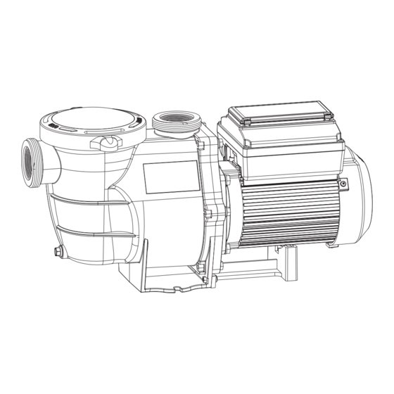
PUMP OVERVIEW Motor Features Variable Speed Pump can be programmed to run at specific speeds and time intervals for maximum • High Efficiency Permanent Magnet Synchronous operating efficiency and energy conservation for a Motor (PMSM) variety of inground pools. • Superior speed control •... -
Page 5: Installation
INSTALLATION Only a qualified plumbing professional should install the Variable Speed Pump. Refer to “Important Pump Warning And Safety Instructions” on pages ii - iii for additional installation and safety information. Location Note: Do not install this pump within an outer enclosure or beneath the skirt of a hot tub or spa unless marked accordingly. -
Page 6: Electrical Installation
Electrical Installation RISK OF ELECTRICAL SHOCK OR ELECTROCUTION. RISK OF ELECTRICAL SHOCK OR ELECTROCUTION. This pump must be installed by a licensed or This pump must be installed by a licensed or certified electrician or a qualified service professional in accordance with the National Electrical Code and all applicable local electrician or a qualified service professional in accordance with the National Electrical Code and all applicable local electrician or a qualified service professional in accordance with the National Electrical Code and all applicable local codes and ordinances. -
Page 7: Operating The Pump
OPERATING THE PUMP OPERATING THE PUMP NOTE: When setting up the Variable Speed Pump, the user must set the pump’s internal clock and establish a NOTE: When setting up the Variable Speed Pump, the user must set the pump’s internal clock and establish an operation schedule n operation schedule by following the steps in this manual. -
Page 8: Using The Operator Control Panel
Using the Operator Control Panel Use the operator control panel to start and stop the Variable Speed Pump, program, set, and change speeds (RPM), and access pump features and settings. Controls and LEDs on Keypad Button 1: Press to select Speed 1 (750 RPM). LED on indicates Speed 1 is active. -
Page 9: Stopping And Starting The Pump
Stopping and Starting the Pump Manual Speed 1 (1-4) Set Speed – Default Starting the Pump Schedule Set Speed Set Start Time 1. Be sure the pump is powered on and the green Be sure the pump is powered on and the green Set Stop Time power LED is on. - Page 10 Operator Control Panel: Pump Menu Guide Operator Control Panel: Pump Menu Guide MENU Press MENU button to access menus Press MENU button to access menus SETTINGS Set Date and Time Date Date Months (1-12) Days (1-31) Years (2016-9999 Plus) Time Time Hours (24hr Mode: 0-23) (12hr Mode: 1-12 AM &...
-
Page 11: Set Minimum Speed (Rpm)
MENU 7. Press the Up or Down arrows to change the minimum arrows to change the minimum speed setting from 450 to 1700 RPM. speed setting from 450 to 1700 RPM. Pump Menu: Settings Pump Menu: Settings 8. Press Enter to save. To cancel, press to save. -
Page 12: Set Screen Contrast
MENU Pump Menu: Settings SETTINGS Set Temperature Unit Set Screen Contrast The default setting is Fahrenheit (°F). The pump can be set The default setting for the LCD screen is 3. Screen to either Celsius (°C) or Fahrenheit (°F). contrast levels can be adjusted from 0 to 5 units for or high lighting conditions. -
Page 13: Setting Password
MENU MENU Pump Menu: Settings Pump Menu: Settings Pump Menu: Speeds 1 Pump Menu: Speeds 1-8 SPEED 1-8 SETTINGS Pump Operating Modes Setting Password The Variable Speed Pump can be programmed in three The Variable Speed Pump can be programmed in three 1. - Page 14 MENU Pump Menu: Speeds 1 Pump Menu: Speeds 1-8 SPEED 1-8 Set Speeds in Manual Mode Set Speeds 1-8 in Schedule Mode 8 in Schedule Mode (Speeds 1-4 Only) In Schedule mode, Speeds 1-8 can be programmed to run a 8 can be programmed to run a a scheduled 1.
-
Page 15: External Control
MENU MENU Pump Menu: External Pump Menu: External Pump Menu: Speeds 1 Pump Menu: Speeds 1-8 EXT CONTROL SPEED 1-8 Control Set Speeds 1-8 in Schedule Mode Schedule Mode External Control (cont.) currently inactive currently inactive This function allows users to control the pump through an This function allows users to control the pump through an external adaptor. - Page 16 MENU Press the Down arrow again, and press arrow again, and press Enter for “Time Duration”. Pump Menu: Features Pump Menu: Features FEATURES 10. Press Enter to change the time. The cursor will to change the time. The cursor will highlight the minutes column.
-
Page 17: Priming Features
MENU Pump Menu: Priming Pump Menu: Priming PRIMING Priming Features Default: ENABLED Default: ENABLED DISABLED/ENABLED Allows Variable Speed Pump to automatically detect if pump if is primed for startup. The Allows Variable Speed Pump to automatically detect if pump if is primed for startup. The Allows Variable Speed Pump to automatically detect if pump if is primed for startup. - Page 18 MENU Pump Menu: Priming Priming PRIMING Setting Priming Features Note: Priming features are only accessible if priming is Priming features are only accessible if priming is “Enabled”. Press Menu. Use Down arrow to scroll to “Priming” and press arrow to scroll to “Priming” and press Enter.
- Page 19 MENU Pump Menu: Thermal Mode Pump Menu: Thermal Mode THERMAL MODE The sensor for Thermal Mode is in the drive, on top of The sensor for Thermal Mode is in the drive, on top of To Set Thermal Mode Speed and Pump Temperature: To Set Thermal Mode Speed and Pump Temperature: the motor.
-
Page 20: Maintenance
MAINTENANCE DO NOT open the strainer pot if Variable Speed Pump fails to prime or if pump has been operating without water in the Variable Speed Pump fails to prime or if pump has been operating without water in the Variable Speed Pump fails to prime or if pump has been operating without water in the strainer pot. -
Page 21: Motor And Drive Care
SERVICING Always disconnect power to the Variable Speed Pump at the circuit breaker and disconnect the communication cable before servi Always disconnect power to the Variable Speed Pump at the circuit breaker and disconnect the communication cable before servi Always disconnect power to the Variable Speed Pump at the circuit breaker and disconnect the communication cable before servicing the pump. Failure to do so could result in death or serious injury to service people, users or others due to electric shock. -
Page 22: Pump Reassembly
Pump Reassembly When installing the replacement shaft seal, use When installing the replacement shaft seal, use Reinstall the pump lid and plastic clamp. See Reinstall the pump lid and plastic clamp. See silicone sealant on the metal portion before pressing silicone sealant on the metal portion before pressing “Cleaning the Pump Strainer Basket”... -
Page 23: Alerts And Warnings
Drive Assembly Removal and Alerts and Warnings Installation, (continued) The Variable Speed Pump displays all alarms and warnings Variable Speed Pump displays all alarms and warnings on the control panel display. When an alarm or warning on the control panel display. When an alarm or warning Before installing this product, read and follow all Before installing this product, read and follow all condition exists, the corresponding light will be lit... -
Page 24: Troubleshooting
TROUBLESHOOTING Always disconnect power to the Variable Speed Always disconnect power to the Variable Speed Pump at the circuit breaker and disconnect the communication cable before servicing the Pump at the circuit breaker and disconnect the communication cable before servicing the pump. - Page 25 Problem Possible Cause Corrective Action Could appear as a UV1=“Low Voltage” alarm. Check voltage at motor terminals and at panel while Electrical problem. pump is running. If low, see wiring instructions or consult power company. Check for loose connections. Check line voltage; if less than 90% or more than 110% of rated voltage consult a licensed electrician.
-
Page 26: Replacement Parts
REPLACEMENT PARTS Parts Listing: 5120/5122 Parts Listing: 72554 Variable Speed Pump Installation and User’s Guide... - Page 27 Ref. No. Part No. Description 647276571 Cover 65431042080 o-ring 647276803001 Basket 647276801080 Pump housing 65431032080 o-ring 65212025000 Screw ST4.2X38 647254703080 Diffuser 647274871000 Impeller 65431045080 o-ring 647276802080 Pump cover 65244015000 Gasket M10 5225003000 3/8-16*1 1/2 UNC Screw 65028014000 Seal assembly 65221008000 Screw M10*25 47276804080...
-
Page 28: Pump Dimensions
Pump Dimensions 5120/5122 72554 Electrical Specifications Model Volte / HZ Amps 1.5HP 750~3450 230V/50HZ/60HZ 0.4~5.5 5120 72554 1.5HP 750~3450 230V/50HZ/60HZ 0.4~5.5 750~3450 230V/50HZ/60HZ 0.5~11.5 5122 Variable Speed Pump Installation and User’s Guide... -
Page 29: Pump Performance Curves
Pump Performance Curves 5120 72554... - Page 30 5122...
- Page 31 SAVE THESE INSTRUCTIONS SAVE THESE INSTRUCTIONS...
Need help?
Do you have a question about the 5120 and is the answer not in the manual?
Questions and answers