
Summary of Contents for XCS HD 104000
- Page 1 High Definition Programmable Frame Line Generator Owner’s Manual Xtended Camera Support, Inc. 5/2015 Rev 1.1...
- Page 2 * Be sure to cover all open video and connector ports when not in use. This will minimize any possible failures. * There are no user serviceable parts inside. * If mounting the Frame Liner with alternative brackets other than what XCS Inc. provides, you must seal all open mounting screw holes to prevent water from entering.
- Page 3 Send it in and your problems will be resolved, we do not offer in field reprogramming options. XCS offers custom software for your needs. Please contact us for a quote of your vision of our design. P a g e...
- Page 4 Thank you for your purchase of the XCS High Definition Frame Line Generator Plus. This is the first design of its kind and the most advanced since the introduction of the XCS DUO Digital Frame Liner over 20 years ago. We set the standard for “drift less” and “stand alone designs” in 1995 and continue these advances for today’s new technologies.
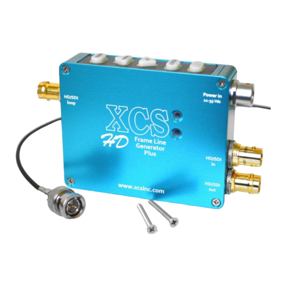
- Page 5 Mounting your Programmable Digital Frame Liner securely. XCS has gone to great lengths to keep the same hole mounting pattern as our previous XCS designed products. Use two screws to prevent it from moving. Keep it flat against a rigid surface. Don’t leave the chassis or mating connectors unprotected from damage due to cable stress or impact damage of any kind.
- Page 6 Editing the MENU pages To select and edit any MENU page is a simple process. 1) Select the MENU page you wish to edit by pressing the MENU button to sequentially scroll through the three different MENU pages FRAMELINE, CENTER MARK, SYSTEM. 2) Use the UP/ DOWN buttons to scroll through the PARAMETER list of editable settings for that page.
- Page 7 Once a valid video input is detected, the VPID Identifier text box remains on for a fixed 10 seconds indicating the video signal input type. Option 2 Running an HD/SDI video signal in, output video to an HD/SDI monitor. HD/SDI MONITOR You are inputting an HD/SDI video signal into the HD-PDL.
- Page 8 For example: The onscreen voltage indicator can be set up to match the actual voltage at the monitor, at the top stage, at the camera while under load, or perhaps the at the battery source. All of these have slightly different CALIBRATION settings and test points for a truly accurate indication on your battery status.
- Page 9 SYSTEM MENU SETTINGS PARAMETER LIST VOLTs DISPLAY ON/OFF/ON WHEN LOW VOLTs THRESHOLD ADJ UP/DOWN (see parameter description for details) VOLTs CALIBRATE ADJ UP/DOWN (see parameter description for details) OUTPUT MENUs to HD/SDI DOWN CONVERTER OFF, 3G to HD, 2K to HD (two separate optional software programs) MENU TIMEOUT OFF, 4, 6, 8, 10...
- Page 10 This allows for quick adjustments of your last setting. All the settings are stored in nonvolatile memory even after the unit is powered down. There are no internal batteries to worry about changing. This has been an XCS standard for all our product designs. 10 |...
- Page 11 FRAMELINE MENU SETTINGS Factory Preset: ON, Zebra bar White & Blue, Width 1 The FRAMELINE parameter settings are independent for both HD-SDI and analog. Both settings are independently memorized and stored in the HD-PDL memory for immediate recall of your setting. So you can have a red frame line in HD-SDI and a black &...
- Page 12 CENTER MARK: ON, OFF. Turns ON/OFF the center mark. STYLE: CROSSHAIR OR DOT. Selectable Crosshair or Dot on screen. V POSITION: ADJ UP/DOWN. Adjusts position of the center mark using the up & down buttons. H POSITION: ADJ UP/DOWN. Adjusts position of the center mark using the up & down buttons. COLOR: BLACK, RED, GREEN, BLUE, WHITE, MAGENTA, CYAN.
- Page 13 VOLTs THRESHOLD: ADJ UP/DOWN (On screen text box will appear) Factory Preset: 12.5 volts Under this parameter you are able to program a voltage point at which you would like to run your batteries down to at their lowest voltage point. We recommend you consult your battery pack supplier or battery handbook to determine the lowest voltage your battery chemistry can be safely run, given your current draw.
- Page 14 Programming the VOLTs CALIBRATE When you SELECT to edit the VOLTs CALIBRATE menu setting, a text box will appear in addition to the SYSTEM MENU on the upper left side displaying: ADJUST THE VOLTAGE DISPLAYED AS REQUIRED TO CALIBRATE. This is directing you to use the UP/DOWN pushbuttons and voltage box on the lower right to set the voltage.
-
Page 15: Operation Time
Displays software Serial Number, Board Revision, and Firmware version numbers when you press the SELECT button. A security feature XCS started over 18 years ago by coding the serial number in the memory chip so it can’t be removed. This makes the unit easier to trace in case it is lost or stolen. - Page 16 ADJUST THE THRESHOLD THAT IS DISPLAYED IN THE VOLTAGE FIELD Refer to pg.13 for setting. 27.0 Example of voltage display of battery status. Color will vary depending on battery status. SYSTEM MENU SETTINGS Indicates which connector the MENUs are OUTPUT MENU’s HD/ SDI output on.
- Page 17 Table 1: Supported Input SMPTE Digital Formats Other formats may work but are untested. 720 x 487 59.94 Hz 720 x 576 50 Hz 1280 x 720 p 23.98, 24, 25, 29.97, 30, 50, 59.94, 60 Hz 1920 x 1080 i 50, 59.94, 60 Hz 1920 x 1080 p 23.98, 24, 25, 29.97, 30 Hz...
Need help?
Do you have a question about the HD 104000 and is the answer not in the manual?
Questions and answers