Table of Contents
Advertisement
Quick Links
Advertisement
Table of Contents

Summary of Contents for GHM Greisinger GRA 0420 WK
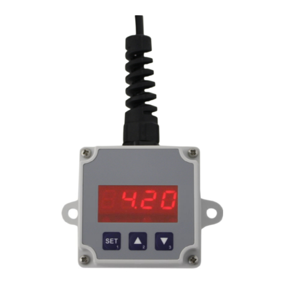
- Page 1 E30.0.1X.6C-04 page 1 v. 12 Manual for connection and operating of GRA 0420 WK GRA 010 WK as of version 1.0 WEEE-Reg.-Nr. DE93889386 GHM GROUP - Greisinger GHM Messtechnik GmbH | Hans-Sachs-Str. 26 | 93128 Regenstauf | GERMANY Tel.: +49 9402 9383-0 | info@greisinger.de...
-
Page 2: Table Of Contents
INDEX INTRODUCTION ..............................2 SAFETY REGULATIONS ............................3 ELECTRIC CONNECTION ........................... 4 Connection assignment for GRA 0420 WK / GRA 010 WK: ................4 Connection example: ............................4 3.2.1 GRA...WK: switching of a relay ....................... 4 Connection example: switching of a relay with combined supply for measurement section and output section ..4 3.2.2... -
Page 3: Safety Regulations
E30.0.1X.6C-04 Operating Manual GRA0420WK / GRA010WK page 3 v. 12 Safety regulations This device was designed and tested considering the Safety regulations for electronic measuring devices. Faultless operation and reliability in operation of the measuring device can only be assured if the General Safety Measures and the devices specific safety regulation mentioned in this users manual are considered. -
Page 4: Electric Connection
Wrong connection may lead to the destruction of the device, in which case we cannot assume any warranty. ! Mind for the GRA0420WK the maximum input current rating of 40mA under any circumstances! 3.1 Connection assignment for GRA 0420 WK / GRA 010 WK: contact-... -
Page 5: Configuration: (Display Adjustment To The Transmitter)
E30.0.1X.6C-04 Operating Manual GRA0420WK / GRA010WK page 5 v. 12 4 Configuration: (display adjustment to the transmitter) Please note: The storage of a configuration value will be done by switching to the next configuration value (via button 1). When configuration is active and no button is pressed for more than 60 seconds the configu- ration will be cancelled. -
Page 6: Selection Of The Output Function
E30.0.1X.6C-04 Operating Manual GRA0420WK / GRA010WK page 6 v. 12 4.2 Selection of the output function When pressing button 1 again, the display will show “outP“. (Output) Use button 2 and button 3 (middle or right button) to select the desired output-function. to select Output Description... -
Page 7: Switching Points / Alarm-Boundaries
E30.0.1X.6C-04 Operating Manual GRA0420WK / GRA010WK page 7 v. 12 5 Switching points / alarm-boundaries: Please note: The storage of a configuration value will be done by switching to the next configuration value (via button 1). When configuration is active and no button is pressed for more than 60 seconds the configu- ration will be cancelled. -
Page 8: Min-/Max-Alarm
E30.0.1X.6C-04 Operating Manual GRA0420WK / GRA010WK page 8 v. 12 5.2 Min-/Max-Alarm This chapter describes how to configure the device‘s alarm boundaries for min-/max-alarm-monitoring. This instruction demands that you selected “AL“ as your desired output function. , the device will display “AL.Hi“. (maximum alarm-value) Press button 1 (when not already done) Use button 2 and button 3 to set the desired value, the device should turn on its maximum-alarm. -
Page 9: Offset- And Slope-Adjustment
E30.0.1X.6C-04 Operating Manual GRA0420WK / GRA010WK page 9 v. 12 6 Offset- and slope-adjustment The offset and slope-adjustment function can be used for compensating the tolerance of the used sensor, resp. for vernier adjustment of the used transducer / transmitter. Please note: The storage of a configuration value will be occur by switching to the next configuration value (via button 1). -
Page 10: Errorcodes
E30.0.1X.6C-04 Operating Manual GRA0420WK / GRA010WK page 10 v. 12 8 Errorcodes: When detecting an operating state which is not permissible, the device will display an error code. The following error codes are defined: Err.1: Exceeding of the measuring range Indicates that the valid measuring range of the device has been exceeded. -
Page 11: Specification
E30.0.1X.6C-04 Operating Manual GRA0420WK / GRA010WK page 11 v. 12 9 Specification GRA 0420 WK... GRA 010 WK... Input signal: 4 ... 20 mA (2-wire) 0 ... 10V (3-wire) Voltage load: < 5.5 V Input resistance: ca. 30 kOhm max. permissible input:... - Page 12 E30.0.1X.6C-04 Operating Manual GRA0420WK / GRA010WK page 12 v. 12...
Need help?
Do you have a question about the GRA 0420 WK and is the answer not in the manual?
Questions and answers