Table of Contents
Advertisement
Quick Links
Advertisement
Table of Contents

Subscribe to Our Youtube Channel
Summary of Contents for Benchmark 1150-002
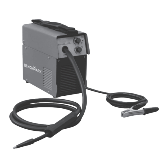
- Page 1 INVERTER FLUX-CORE WELDER KIT 120V 60Hz 5 year limited warranty on tool READ ALL INSTRUCTIONS BEFORE FIRST USE. KEEP THIS MANUAL FOR FUTURE REFERENCE. KEEP AWAY FROM CHILDREN. 229683 Inverter FC 125 WEAR CSA APPROVED WEAR EAR WEAR A EYE PROTECTION PROTECTION FACE MASK...
-
Page 2: Product Specifications
PRODUCT SPECIFICATIONS BENCHMARK FLUX CORE WELDER Input Voltage 1ph 120V Input Power (KVA) 2.76 Input Current (A) Output Current Range (A) 30-125A Max. Output Current 125A/20.3V No-load Voltage (V) Rated Duty Cycle 30% at 90A Power Factor 0.67 Protection Class... -
Page 3: Table Of Contents
Table of Contents ..................2 General Safety Warnings ................3 Specific Safety Rules for Flux Core Welder ............. 7 Safety Symbols ..................... 9 Know Your Benchmark Flux Core Welder ............10 Assembly ..................... 12 Operation ....................17 Troubleshooting ..................22 Exploded View .................... -
Page 4: General Safety Warnings
GENERAL SAFETY WARNINGS IMPORTANT SAFETY INSTRUCTIONS Read and understand all safety and operational instructions. failure to follow the safety rules listed below and other basic safety precautions may result in serious personal injury. Keep this manual, sales receipts and applicable warranty forms for future reference. - Page 5 1150-002 INVERTER FLUX-CORE WELDER KIT SYMBOL MEANING Always wear non-slip gloves that fit properly to protect your hands and to help you grip the tool. Always wear sturdy clothing with long sleeves and long pants. Never operate the tool while wearing shorts, short sleeve shirt or while shirtless.
- Page 6 GENERAL SAFETY INSTRUCTIONS WARNING: OWNER’S MANUAL. Read and understand this owner’s manual BEFORE using machine. TRAINED OPERATORS ONLY. Untrained operators have a higher risk of being hurt or killed. Only allow trained/supervised people to use this machine. When machine is not being used, dis- connect power, remove switch keys, or lock-out machine to prevent unauthorized use - especially around children.
- Page 7 1150-002 INVERTER FLUX-CORE WELDER KIT AWKWARD POSITIONS. Keep proper footing and balance at all times when operating machine. Do not overreach! Avoid awkward hand positions that make workpiece control difficult or increase the risk of accidental injury. CHILDREN & BYSTANDERS. Keep children and bystanders at a safe distance from the work area.
-
Page 8: Specific Safety Rules For Flux Core Welder
SPECIFIC SAFETY RULES FOR FLUX CORE WELDER WARNING: In order to avoid mistakes that could cause serious injury, read the following steps carefully and understand them thoroughly before using this welder. WELDING FUMES. Breathing welding fumes can cause suffocation or poisoning without warning. - Page 9 1150-002 INVERTER FLUX-CORE WELDER KIT and explode. Exploding pressurized gas cylinders can cause serious property damage, personal injury, or death. ELECTRIC AND MAGNETIC FIELDS (EMF). Welding operations create EMF around the welding equipment and workpieces. Workers who have pacemakers must consult with their physician before using this equipment or being within 50 feet of welding operations.
-
Page 10: Safety Symbols
SAFETY SYMBOLS The rating plate on your tool may show symbols. These represent important information about the product or instructions on its use. WARNING: Please read all of the safety and operating instructions carefully before using this tool. Please pay particular attention to all sections of this User Guide that carry warning symbols and notices. -
Page 11: Know Your Benchmark Flux Core Welder
1150-002 INVERTER FLUX-CORE WELDER KIT KNOW YOUR BENCHMARK FLUX CORE WELDER Attention Always be sure that the machinery is switched off and unplugged before adjusting or checking function on the machinery. FUNCTIONS 1. POWER INDICATOR 2. OVERLOAD INDICATOR 3. WELDING CURRENT 4. - Page 12 POWER INDICATOR When the machine is turned on, the power indicator will be on. Overload Indicator When this indicator is on, it shows the machine is overloaded and the internal temperature is too high. Weld output will turn off automatically but the fan will still be working.
-
Page 13: Assembly
1150-002 INVERTER FLUX-CORE WELDER KIT ASSEMBLY INSTRUCTIONS FOR SHOULDER STRAP INSTALLATION Step 1 Step 2 Get the strap through the buckle Leave 165 mm on each end Put the shoulder pad in the middle of the strap Step 4 Step 3... - Page 14 3. Install the wire roller Before installing any welding wire into the unit, the properly-sized groove must be positioned on the wire drive mechanism. Adjust the drive roller according to the following steps, see following picture about the wire feeder structure: Drive tension arm Gun liner Inlet guide tube...
- Page 15 1150-002 INVERTER FLUX-CORE WELDER KIT RECOMMENDED WIRE FLUX CORED WIRE SELECTION---- E71T-GS 3.6 Depending on the wire diameter, select the correct groove according to the following table about the relationship between wire diameter and wire roller groove size. Wire Diameter...
- Page 16 If not, change the drive roller as described above. 4.2.3 Unwrap the spool of wire and then find the leading end of the wire. The wire goes through a hole in the outer edge of the spool and is bent over the spool edge to prevent the wire from unspooling BUT DO NOT UNHOOK IT at this point.
- Page 17 1150-002 INVERTER FLUX-CORE WELDER KIT 4.2.7. After checking to make sure that your welder is disconnected from the AC power source, free the leading end of the wire from the spool, but do not let go of it until told to do so, or the wire will unspool itself.
-
Page 18: Operation
5.2. Turn the drive tension adjustment knob clockwise, increasing the drive tension until the wire seems to feed smoothly without slipping. WARNING: Arc flash can injure eyes! To reduce the risk of arc flash, make sure that the wire coming out of the end of the torch does not come into contact with work piece, ground clamp or any grounded material during the drive tension setting process, or arcing will occur. - Page 19 1150-002 INVERTER FLUX-CORE WELDER KIT 3.2. Angle B can be varied for two reasons: to improve the ability to see the arc in relation to the weld puddle and to direct the force of the arc. 4. Distance from the work piece If the nozzle is held off the work piece, the distance between the nozzle and the work piece should be kept constant and should not exceed 1/4"...
- Page 20 Travel direction is the direction the torch is moved along the weld joint in relation to the weld puddle. The torch is either PUSHED into the weld puddle or PULLED away from the weld puddle. Weld puddle Pull Push For most welding jobs, you will pull the torch along the weld joint to take advantage of the greater weld puddle visibility.
- Page 21 1150-002 INVERTER FLUX-CORE WELDER KIT HORIZONTAL POSITION. This is performed very much the same as the flat weld except that angle B (see HOLDING THE TORCH) is such that the wire is directed more toward the metal above the weld joint. This is...
- Page 22 NOTE: WHEN USING SELF-SHIELDING FLUX-CORED WIRE it is very important to thoroughly chip and brush the slag off each completed weld bead before making another pass or the next pass will be of poor quality. Fillet Weld Joints. Most fillet weld joints, on metals of moderate to heavy thickness, will require multiple pass welds to produce strong joint.
-
Page 23: Troubleshooting
1150-002 INVERTER FLUX-CORE WELDER KIT MAINTENANCE The welder needs regular maintenance: • Periodically clean dust, dirt, grease, etc. from your welder. Every six months, or as necessary, remove the cover panel from the welder and air blow any dust and dirt that may have accumulated inside the welder. -
Page 24: Exploded View
EXPLODED VIEW... -
Page 25: Parts List
1150-002 INVERTER FLUX-CORE WELDER KIT PARTS LIST WARNING: When servicing, use only original equipment replacement parts. The use of any other parts may create a safety hazard or cause damage to the brushless power washer. Any attempt to repair or replace electrical parts on this power washer may create a safety hazard unless repairs are performed by a qualified technician. -
Page 26: Warranty
WARRANTY BENCHMARK FLUX CORE WELDER If this Benchmark tool fails due to a defect in material or workmanship within five years from the date of purchase, return it to any Home Hardware store with the original bill of sale for exchange. 3-year warranty for the battery and charger. This warranty does not include expendable parts including but not limited to blades, brushes, belts, light bulbs. - Page 27 1150-002 INVERTER FLUX-CORE WELDER KIT...
- Page 28 INVERTER FLUX-CORE WELDER KIT 120V 60Hz 5 year limited warranty on tool 1150-002 BENCHMARK TOOLS CANADA Made in China ST. JACOBS, ONTARIO N0B 2N0 © 2022 Home Hardware Stores Limited CUSTOMER SERVICE/TECH SUPPORT 1-866-349-8665 * This Benchmark product carries a five (5) year LIMITED warranty against defects in workmanship and materials.
Need help?
Do you have a question about the 1150-002 and is the answer not in the manual?
Questions and answers