
Related Manuals for Benchmark 1150-003

Summary of Contents for Benchmark 1150-003
- Page 1 INVERTER MULTI-PROCESS WELDER KIT 120V or 230V 60Hz 5 year limited warranty on tool...
-
Page 2: Product Specifications
PRODUCT SPECIFICATIONS BENCHMARK INVERTER MIG/FLUX/STICK WELDER Input Voltage 1ph 120V 1ph 230V Function Input Power (KVA) Input Current (A) Output Current Range (A) 30~100 20-85 30~200 20-170 Max. Output Current 100A/19V 85A/23.4V 200A/24V 170A/26.8V No-load Voltage(V) Rated Duty Cycle 35 @100A... -
Page 3: Table Of Contents
Table of Contents ..................2 General Safety Warnings ................3 Specific Safety Rules for Inverter MIG/Flux/Stick Welder ......... 7 Safety Symbols ..................... 9 Know Your Benchmark Inverter MIG/Flux/Stick Welder ......... 10 Power Supply ....................12 Assembly ..................... 15 Operation ....................22 Troubleshooting .................. -
Page 4: General Safety Warnings
GENERAL SAFETY WARNINGS IMPORTANT SAFETY INSTRUCTIONS Read and understand all safety and operational instructions. Failure to follow the safety rules listed below and other basic safety precautions may result in serious personal injury. Keep this manual, sales receipts and applicable warranty forms for future reference. - Page 5 1150-003 INVERTER MULTI-PROCESS WELDER KIT SYMBOL MEANING Always wear non-slip gloves that fit properly to protect your hands and to help you grip the tool. Always wear sturdy clothing with long sleeves and long pants. Never operate the tool while wearing shorts, short sleeve shirt or while shirtless.
- Page 6 GENERAL SAFETY INSTRUCTIONS WARNING: OWNER’S MANUAL. Read and understand this owner’s manual BEFORE using machine. TRAINED OPERATORS ONLY. Untrained operators have a higher risk of being hurt or killed. Only allow trained/supervised people to use this machine. When machine is not being used, dis- connect power, remove switch keys, or lock-out machine to prevent unauthorized use - especially around children.
- Page 7 1150-003 INVERTER MULTI-PROCESS WELDER KIT AWKWARD POSITIONS. Keep proper footing and balance at all times when operating machine. Do not overreach! Avoid awkward hand positions that make workpiece control difficult or increase the risk of accidental injury. CHILDREN & BYSTANDERS. Keep children and bystanders at a safe distance from the work area.
-
Page 8: Specific Safety Rules For Inverter Mig/Flux/Stick Welder
SPECIFIC SAFETY RULES FOR INVERTER MIG/ FLUX/STICK WELDER WARNING: In order to avoid mistakes that could cause serious injury, read the following steps carefully and understand them thoroughly before using this welder. WELDING FUMES. Breathing welding fumes can cause suffocation or poisoning without warning. - Page 9 1150-003 INVERTER MULTI-PROCESS WELDER KIT gas cylinder. Damaging the outside of the cylinder can cause the cylinder to crack and explode. Exploding pressurized gas cylinders can cause serious property damage, personal injury, or death. ELECTRIC AND MAGNETIC FIELDS (EMF). Welding operations create EMF around the welding equipment and workpieces.
-
Page 10: Safety Symbols
SAFETY SYMBOLS The rating plate on your tool may show symbols. These represent important information about the product or instructions on its use. WARNING: Please read all of the safety and operating instructions carefully before using this tool. Please pay particular attention to all sections of this User Guide that carry warning symbols and notices. -
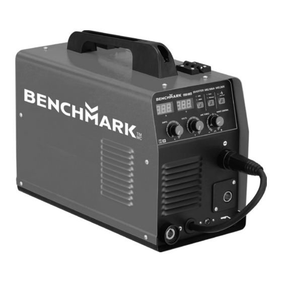
Page 11: Know Your Benchmark Inverter Mig/Flux/Stick Welder
1150-003 INVERTER MULTI-PROCESS WELDER KIT KNOW YOUR BENCHMARK INVERTER MULTI-PROCESS WELDER Front View Rear View Side View... - Page 12 FUNCTIONS Handle Welding voltage meter Welding current meter Regulator - wire feeding speed (MIG mode), welding current (MMA mode) Regulator - welding voltage (MIG mode) Positive output connector Polarity switching cable MIG/MMA mode selector 2T/4T mode selector 10 Gas test 11 Inductor adjustment (MIG mode), arc force (MMA mode) 12 Negative output connector 13 MIG welding torch connector...
-
Page 13: Power Supply
1150-003 INVERTER MULTI-PROCESS WELDER KIT POWER SUPPLY Before installing the machine, consider the availability and proximity of the required power supply circuit. If an existing circuit does not meet the requirements for this machine, a new circuit must be installed. To minimize the... - Page 14 Nominal Voltage ..... 208V, 220V, 230V, 240V Cycle ..............60 Hz Phase ............Single-Phase Power Supply Circuit ........50 Amps Plug/Receptacle ......... NEMA 6-50 6-50 GROUNDED RECEPTACLE Grounding Prong 6-50 PLUG Current Carrying Prongs Figure 1. NEMA 6-50 plug and receptacle. CIRCUIT REQUIREMENTS FOR 115V ADAPTOR This machine can be converted to operate on a power supply circuit that has a verified ground and meets the requirements listed below.
- Page 15 1150-003 INVERTER MULTI-PROCESS WELDER KIT The wire with green insulation (with or without yellow stripes) is the equipment- grounding wire. If repair or replacement of the power cord or plug is necessary, do not connect the equipment-grounding wire to a live (current carrying) terminal.
-
Page 16: Assembly
ASSEMBLY Wire Spool Installation / Wire Setup 1. Turn the power Switch OFF and unplug the Welder before proceeding. 2. Pull up on the Door Latch, then open the Door. 3. 1-2 pound Wire Spool installation: Remove the Wingnut, spring and washers. If replacing a Spool, remove the old Spool and all remaining wire from the liners. - Page 17 1150-003 INVERTER MULTI-PROCESS WELDER KIT NOTICE: If Wire Spool can spin freely, Wingnut is too loose. This will cause the welding wire to unravel and unspool which can cause tangling and feeding problems. 6. 10-12 pound Wire Spool installation: Remove the Wingnut, spring and washers.
- Page 18 12. Feed Roller instructions: Check that the Feed Roller is correct for the type of wire being used (solid core or flux- cored) and that it is turned to properly match the wire size marked on the Wire Spool: a. Unscrew the Feed Roller Knob counterclockwise.
- Page 19 1150-003 INVERTER MULTI-PROCESS WELDER KIT 13. Loosen the Knob on the Wire Feed mechanism, then insert the Gun Cable Connector through the hole on the Welder front and into the socket on the Wire Feed. 14. Ensure that the Gun Cable...
- Page 20 17. DCEP Direct Current Electrode Positive Wire Setup for Solid Core (gas shielded) welding: a. Plug Ground Clamp Cable into Negative (–) Socket. Plug polarity switch cable into Positive (+) Socket. Twist cables clockwise all the way to lock in place. b.
- Page 21 1150-003 INVERTER MULTI-PROCESS WELDER KIT IMPORTANT Securely hold onto the end of the welding wire and keep tension on it during the following steps. If this is not done, the welding wire will unravel and unspool which can cause tangling and feeding problems.
- Page 22 24. Do not touch the Gun’s Trigger. Plug the Power Cord into a properly grounded, GFCI protected 120 VAC (20 amp rated) or 240 VAC receptacle that matches the plug and turn the Power Switch ON. The circuit must be equipped with delayed action-type circuit breaker or fuses.
-
Page 23: Operation
1150-003 INVERTER MULTI-PROCESS WELDER KIT 26. To check the wire’s drive tension, press and hold Trigger to feed the wire against a piece of wood from 2 to 3 inches away. If the wire stops instead of bending, unplug the Welder, slightly tighten the Feed Tensioner clockwise, and try again. - Page 24 1. To set up optional Spool Gun (sold separately), plug Ground Clamp Cable into Negative (–) Socket. Plug polarity switch cable into Positive (+) Socket. Twist cables clockwise all the way to lock in place. 2. Loosen the Knob on the Wire Feed mechanism, then insert the Spool Gun Cable Connector through the hole on the Welder front and into the socket on the Wire Feed.
- Page 25 1150-003 INVERTER MULTI-PROCESS WELDER KIT Make practice welds on pieces of scrap to practice technique before welding anything of value. Warning To prevent serious injury, fire and burns: Keep welding tip clear of grounded objects whenever unit is plugged in and turned on.
- Page 26 SETTING UP THE WELD 1. Make practice welds on pieces of scrap the same thickness as your intended workpiece to practice technique before welding anything of value. Clean the weld surfaces thoroughly with a wire brush or angle grinder; there must be no rust, paint, oil, or other materials on the weld surfaces, only bare metal.
- Page 27 1150-003 INVERTER MULTI-PROCESS WELDER KIT 4. Turn the Power Switch to the OFF position, then plug the Power Cord into a properly grounded, GFCI protected 120 VAC (20 amp rated) or 230 VAC receptacle that matches the plug. The circuit must be equipped with delayed action-type circuit breaker or fuses.
- Page 29 1150-003 INVERTER MULTI-PROCESS WELDER KIT NOTE: If welder is used too long, a warning, the code “E01” appears in the current LCD and the unit automatically shuts down. The welder automatically returns to service after cooling off. Should this occur, rest the MIG...
- Page 31 1150-003 INVERTER MULTI-PROCESS WELDER KIT DUTY CYCLE (DURATION OF USE) This Welder has an internal thermal protection system to help prevent this sort of over-stress. When the Welder overheats, it automatically shuts down and a warning screen appears in the LCD Display window.
- Page 32 STICK WELDING 1. Turn the Power Switch to the OFF position, then plug the Welder into a properly grounded, GFCI protected, 120 VAC (20 amp rated) outlet or 230 V outlet. The circuit must be equipped with delayed action-type circuit breaker or fuses. 2.
- Page 33 1150-003 INVERTER MULTI-PROCESS WELDER KIT...
- Page 35 1150-003 INVERTER MULTI-PROCESS WELDER KIT...
- Page 37 1150-003 INVERTER MULTI-PROCESS WELDER KIT...
- Page 39 1150-003 INVERTER MULTI-PROCESS WELDER KIT...
- Page 40 MAINTENANCE...
-
Page 41: Troubleshooting
1150-003 INVERTER MULTI-PROCESS WELDER KIT TROUBLESHOOTING... -
Page 43: Exploded View
1150-003 INVERTER MULTI-PROCESS WELDER KIT EXPLODED VIEW... -
Page 44: Parts List
For more information, call the Toll-free Helpline, at 1-866-349-8665; Monday - Friday: 9am to 5pm Eastern Standard Time. Always order by key number. Key# Part # Part Name 1150-003-001 Polarity Switching Cable 1150-003-002 MIG Torch Flange 1150-003-003 Quick Connector 1150-003-004... -
Page 45: Warranty
WARRANTY BENCHMARK INVERTER MIG/FLUX/STICK WELDER If this Benchmark tool fails due to a defect in material or workmanship within five years from the date of purchase, return it to any Home Hardware store with the original bill of sale for exchange. 3-year warranty for the battery and charger. This warranty does not include expendable parts including but not limited to blades, brushes, belts, light bulbs. - Page 46 INVERTER MULTI-PROCESS WELDER KIT 5 year limited warranty on tool...
Need help?
Do you have a question about the 1150-003 and is the answer not in the manual?
Questions and answers