
Summary of Contents for MEGADYNE MEGA POWER
- Page 1 Electrosurgical Generator SERVICE MANUAL ©Copyright 2008. All rights reserved Service Manual Part # 3000106-01 Rev -D 2008-05-12...
- Page 2 ©2008 Megadyne Medical Products. All rights reserved. Megadyne is a registered trademark of Megadyne Medical Products. Mega Power™ is a trademark of Megadyne Medical Products. Mega Power Patent numbers: D491,666 D491,667 Mega 2000 is a registered trademark of Megadyne Medical Products...
-
Page 3: Table Of Contents
Table of Contents 1. Preface and Service Center Information ………..……………………………...…..1 2. Limited Warranty ……………………………………………..…………………………2 3. Introduction and General Description……………………………………….………...3 4. List of Assemblies……………………………………………………………………….3 5. Warnings…………………………………………………………………………………4 6. Cautions………………………………………………………………………………….5 7. Symbols…………………………………………………………………………………..6 8. Operating Instructions………………………………………………………………… 7 9. Front Panel Controls, Indicators, and Receptacles………………………………..11 Power Switch Cut Modes: ACE, Pure Cut, Blend………………..……………..12... - Page 4 23. Appendix…………………………………………………………………………. …...58 Safety Compliance Applicable Particular Requirements Electromagnetic Compliance...
-
Page 5: Preface And Service Center Information
Preface This service manual is for use only by qualified and trained personnel. It is intended for servicing the Megadyne Mega Power Electrosurgical Generator only. For clinical use of this system, please refer to the Mega Power User’s Manual. Service Centers/Shipping Instructions Maintenance/Service It is recommended that maintenance calibration testing be performed at annual intervals. -
Page 6: Limited Warranty
The Mega Power Electrosurgical Generator is warranted to be free of defects under normal use and maintenance for two years from the date of purchase. Megadyne will, at its option, repair or replace the defective product without charge, using new or remanufactured parts. -
Page 7: Introduction And General Description
Introduction and General Description The Megadyne Mega Power Electrosurgical Generator is designed to produce radio frequency (RF) current for cutting and coagulation during surgical procedures. It is an isolated output generator. This manual describes the attributes and specifications of the generator, describes the internal workings, and provides a guide to the procedures necessary for calibrating, testing and servicing the unit. -
Page 8: Warnings
Warnings The warnings given below pertain to testing, calibration, and servicing of the generator. The service technician should also be aware of the warnings given in the Operators’ Manual for clinical use of the generator. For operation of the generator, connect the power to a properly grounded •... -
Page 9: Cautions
Cautions The cautions given below pertain to testing, calibration, and servicing of the generator. The service technician should also be aware of the cautions given in the user manual for clinical use of the generator Read all instructions prior to installation and operation. •... -
Page 10: Symbols
Symbols Symbol Description ON (Power) OFF (Power) Read instructions prior to use Generator output is floating with respect to ground Defibrillator proof type CF equipment Dangerous Voltage Equipotentiality Foot Switch Speaker Fuse Return electrode connection Hand control receptacle Foot control receptacle... -
Page 11: Operating Instructions
Operating Instructions With the generator in the “OFF” position be sure that the power cord is fully inserted into both the generator receptacle on the back of the generator and into the appropriate grounded outlet (figure 1). The generator will function in either the 100 or 240 volt modes depending on the power applied to the generator. - Page 12 Patient Return Electrodes: Install a patient return electrode according to the electrode manufacturer’s instructions for use. Megadyne recommends the use of the Mega Soft™ family of Reusable Patient Return Electrodes, however, the Mega Power Electrosurgical Generator is compatible with all approved return electrodes. Insert the return electrode cable into the proper receptacle (figure 3).
- Page 13 Active Accessories: The Active Accessories are the monopolar hand switching pencils, electrodes, monopolar foot cords, and bipolar cords. Megadyne recommends the use of the Megadyne family of Active Accessories, including E-Z Clean electrodes. Fully insert the Active Accessories into their appropriate receptacles ensuring that no metal is exposed (figure 4) Powering the Generator: Turn on the generator by placing the “ON/OFF”...
- Page 14 Modes: Select the proper mode for monopolar “CUT” and “COAG” by depressing the appropriate mode key (figure 5). The indicator light on that key will illuminate when the mode has been selected. Figure 5. Activating the Generator: Monopolar accessories attached to the monopolar hand switching receptacles may be activated by depressing either the “CUT”...
-
Page 15: Front Panel Controls, Indicators, And Receptacles
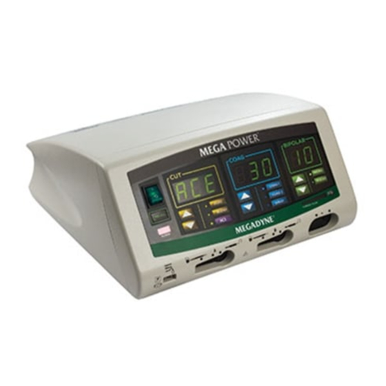
Front Panel Controls, Indicators, and Receptacles The Mega Power generator is designed as a full-functioning, easy to use electrosurgical unit for cutting and coagulating tissue (figure 6). Figure 6. Information regarding Mega Power functions and descriptions are detailed on the pages... -
Page 16: Power Switch Cut Modes: Ace, Pure Cut, Blend
The following descriptions correspond to controls, indicators, and receptacles on the front panel of the generator shown below (figure 7). Figure 7. POWER: The power on/off switch is located in the top left-hand corner of the unit. The unit is turned “ON” when the ‘|’ is depressed and the light above the switch illuminates. The generator is turned “OFF”... -
Page 17: Coag Modes: Standard, Spray, Coag W/ Cut
Standard Coag mode. Powering down the system will also return the Mega Power to the Standard Coag mode. The second Coag mode can easily be recalled (if it was the last mode used) upon start up by pressing the RECALL key or simply use the instructions above to activate the mode Selecting the “SPRAY”... -
Page 18: Bipolar Mode: Standard, Macro
When the bipolar mode is used the current will flow between the two tips of the instrument and will desiccate tissue. The bipolar mode can be activated with either a hand switching device, or with a bipolar footswitch. The Mega Power offers two bipolar settings, a standard/micro bipolar and a macro bipolar. Standard/Micro Bipolar The Mega Power automatically boots up in the Standard/Micro bipolar setting. -
Page 19: Bipolar Current Monitor
2). Or, simply turn the main power switch off on the front panel. The Mega Power bipolar current meter tone will need to be turned on as instructed above each time the unit is powered on if the tone is desired during the case. -
Page 20: Bipolar And Return Patient Return Electrodes And Alarm
Patient Return Electrode Receptacle: This receptacle accepts both single plate and split plate return electrodes. Megadyne recommends use of the Mega Soft Reusable Patient Return Electrode family of products with the Mega Power electrosurgical generator. Patient Return Electrode Alarm: When the generator is turned “ON”... -
Page 21: Rear Panel Controls, Indicators, And Receptacles
A receptacles on the front of the generator. The B footswitch will activate accessories in the B receptacles on the front of the generator. Bipolar Footswitch Connector: A Megadyne one pedal footswitch is connected by inserting the keyed connector into the proper receptacle and tightening the threaded collar. -
Page 22: Calibration Check
ESU analyzer. Set the Mega Power to the PURE CUT @ 20 watts, and set the ESU analyzer to 300 ohms. Activate the Mega Power using the footswitch on monopolar A. Verify an audible tone while the ESU is activated. - Page 23 Disconnect the Mega Power monopolar A from the ESU analyzer and connect the Bipolar output to the ESU analyzer. Set the Mega Power Bipolar to 10 watts, and set the ESU analyzer to 100 ohms. Activate the Mega Power using the bipolar footswitch. Verify and an audible tone while the ESU is activated.
- Page 24 58 and 72 ohms. Megadyne recommends a yearly calibration check of the Mega Power Electrosurgical Generator. If your Mega Power is found to be out of calibration, please send your system directly to Megadyne for calibration. Contact Megadyne customer service to obtain an RGA number and shipping instructions prior to sending the Mega Power in for calibration.
-
Page 25: Troubleshooting/Error Codes
Troubleshooting/Error Codes Troubleshooting - follow the steps in the order listed for the appropriate problem. No output power: 1. Check that the generator power switch is in the “on” position. 2. Insure the generator is plugged into a grounded, functioning outlet and that the power cord is securely attached to the receptacle at the rear of the generator. -
Page 26: Monitor Interference
Monitor Interference: Monitor interference can be an artifact of Electrosurgery. Steps to minimize interference are as follows: 1. Insure that the ECG electrode is well attached to the patient through proper skin preparation prior to electrode placement. 2. Insure the electrosurgical cables (active and return) do not cross the cables of the affected equipment. -
Page 27: Error Codes
Error Codes The Mega Power is designed to assist the user in identifying failure modes. When specific conditions are met an error code will be shown in the large displays. If any of the following errors are displayed and are not cleared by turning the system off then on, record the error displayed and call Megadyne Customer Service at 1-800-747-6110 (US only) (International: 1-801-576-9698). - Page 28 Primary Relay The Watchdog has detected the inappropriate activation of the Primary Control Error Relay. MP1 Relay Control The Watchdog Microcontroller has detected inappropriate activation of the Error MP1 Relay. MP2 Relay Control The Watchdog Microcontroller has detected inappropriate activation of the Error MP2 Relay.
-
Page 29: Technical Specifications Safety Compliance
700 hPA (10.2 psi) to 1060 hPA (15.37 psi) Warm-up requirements If the Mega Power is stored outside of the above range, allow the unit to stabilize at room temperature for a minimum of one hour before use. Storage Environment The Mega Power generator is designed and tested for storage within the following environmental parameters. -
Page 30: Output Power Characteristics
Type and Rating of Fuses: 2 each F10.0/250V Electrical properties Nominal Operating Voltage: 100 – 240 VAC Nominal Operating Frequency: 50-60 Hz Output Power Variation Output variation as a function of input variation <5% Output Power Characteristics Mode Power Output Rated Maximum Operating... - Page 31 (self current limiting) of the Megadyne Mega 2000 patient return electrode, the CQM limitation is no longer essential. If a disposable split pad is used with the Mega Power, the system will perform as follows: Acceptable Resistance Range (thermal safety).
-
Page 32: Declaration Of Electromagnetic Emissions
IEC 61000-3-3 domestic purposes. Declaration for Electromagnetic Immunity The Mega Power is intended for use in the electromagnetic environment specified below. The user of the Mega Power should assure that the Mega Power is used in such environment. IEC 60601 Test... -
Page 33: Approved Accessories
Power Electrosurgical Generator. These accessory devices have been tested and are approved for use at the peak voltages listed in this manual. The user is responsible to insure that any other accessories used with the Mega Power ESU are rated for the maximum peak output voltages (reference to diagrams included herein);... -
Page 34: Power Curve Graphs
Power Curve Graphs Ace Power Curve Graphs ACE Cut - Output Power vs Load Resistance 160.0 140.0 120.0 100.0 80.0 60.0 40.0 20.0 1000 1500 2000 2500 3000 3500 Load Resistance (Ohms) - Page 35 ACE - Power Output vs Power Max Rl = 300 Ohms ACE Output at Rated Load Power HF Maximum ACE - HF Voltage vs Output Power Output Power (W)
- Page 36 Pure Cut Output Power Graphs Pure Cut - Output Power vs Load Resistance 300 W 150 W 1000 1500 2000 2500 Load Resistance (Ohms) Pure Cut - Power Output vs Power Max Rl = 300 Ohms Power HF Maximum (W)
- Page 37 Pure Cut - HF Voltage vs Output Power 1600 1400 1200 1000 Output Power (W) Blend Output Power Graphs Blend Cut - Output Power vs Load Resistance 200 W 100 W 1000 1500 2000 2500 Load Resistance (Ohms)
- Page 38 Blend Cut - Power Output vs Power Max Rl = 300 Ohms Power HF Maximum (W) Blend Cut - HF Voltage vs Output Power 1800 1600 1400 1200 1000 Output Power (W)
- Page 39 Standard Coagulation Output Power Graphs Standard Coag and Coag with Cut - Output Power vs Load Resistance 120 W 60 W 1000 1500 2000 2500 3000 Load Resistance (Ohms) Standard Coag and Coag with Cut - Power Output vs Power Max Rl = 500 Ohms Power HF Maximum (W)
- Page 40 Spray Coagulation Output Power Graphs Spray Coag - Output Power vs Load Resistance 120 W 60 W 1000 1500 2000 2500 3000 Load Resistance (Ohms)
- Page 41 Spray Coag - Power Output vs Power Max Rl = 500 Ohms Power HF Maximum (W) Spray Coag - HF Voltage vs Output Power 4000 3500 3000 2500 2000 1500 1000 Output Power (W)
- Page 42 Bipolar Output Power Graphs Bipolar - Output Power vs Load Resistance 1000 1500 2000 2500 Load Resistance (Ohms) Bipolar - Power Output vs Power Max Rl = 100 Ohms Power HF Maximum (W)
- Page 43 Bipolar - HF Voltage vs Output Power Output Power (W)
-
Page 44: Printed Circuit Board Replacement Procedures
For Service Centers and Megadyne trained facilities. Additional information on assembly replacement is available on Mega Power Service and Repair Video Instruction 3000146-01. This instruction is in DVD format and can be viewed by opening InterVideo WinDVD on your personal... - Page 45 Equipment required: Phillips screwdriver • Step 1 – Remove the ESU Cover and Chassis Cover Turn off the generator, Disconnect the power cord from the wall receptacle Remove the five (5) screws that secure the cover (item A) to the chassis. Pull the cover off of the chassis by pulling the ESU cover horizontally toward the rear of the ESU.
- Page 46 Remove the ESU Cover and Chassis Cover , continued Remove the chassis cover (item B): Remove the four (4) screws that secure the Chassis Cover to the Chassis. Lift the front of the Chassis Cover and remove both wire harness connecters from the front panel which connect to the Chassis Cover.
- Page 47 Step 2 – Fuse Replacement Motherboard Fuse Replacement Remove the fuse (item A) by pulling straight up on the fuse until it’s free of the fuse clip. Replace with a new fuse by pressing the fuse straight down until the fuse snaps into place.
- Page 48 Power Entry Module Fuse Replacement Remove the fuses in the Power Entry Module by prying open the access drawer (item B) with a small flat blade screw driver. Replace the fuses in the drawer and return the drawer to the module.
- Page 49 Step 3 – Removal/Replacement of the Controller Board If it is determined in the Troubleshooting Section that the controller board needs replacing, please follow the instructions below: Disconnect the display board ribbon cable (item B) from the controller board by squeezing the sides of the connector (item C) and pulling straight up.
- Page 50 Step 4 – Removal/ Replacement of the Power Conversion Board If it is determined in the Troubleshooting Section that the power conversion board needs replacing, please follow the instructions below: Remove one screw (item A) from associated heat sink . Unlock the controller board from the card guide by pressing the card lock (item C) toward the rear of the ESU.
- Page 51 Step 5 – Removal/Replacement of the Heat Sinks This step applies to item A, left heatsink and item D, right heatsink. Remove the two (2) screws through the access holes (items E, see diagram on next page.) located on the flanking chassis plates attached on each side of the ESU.
- Page 53 Step 6 – Removal/Replacement of the Front Panel Display Remove the four (4) screws securing the front panel display (item A) to the chassis. Disconnect the wires (item B) connecting the front panel to the power entry module (item C) at the power entry module. Disconnect the wire harness that runs from the front panel to the Power Conversion Board (PCB) at the Power Conversion board.
- Page 54 Step 7 – Removal/Replacement the Low Voltage Power Supply Remove the four (4) screws securing the low voltage power supply (item A) to the chassis. Repeat steps in reverse order to install the low voltage power supply. Screw Screw Screw Screw...
- Page 55 Step 8 – Removal/Replacement of the Motherboard Remove the two (2) high-voltage connector screws and fifteen (15) chassis screws securing the motherboard (item A) to the chassis. Pull horizontally towards the front on the high-voltage connector (item B) to remove the motherboard from the chassis. HV Screw Repeat steps in reverse order to install the motherboard.
- Page 56 Step 9 – Removal/Replacement of the footswitch board Loosen the set screw on the volume knob (item A) and remove the volume knob. Remove the nut securing the volume control on the other side of the chassis. Remove six (6) #4-40 screws and two (2) #6-32 screws to remove the footswitch board (item B.
- Page 58 Step 10 – Removal/Replacement of the Power Entry Module Remove the wire connector (item A) at the power entry module (item B). Remove the two screws that secure the power entry module to the chassis and pull towards the rear of the chassis until the power entry module is clear of the chassis. Repeat steps in reverse order to install the power entry module.
-
Page 59: Parts List
Parts List Description Part Number Center Heatsink Assembly 6020089-01 Mother Board Assembly 6020088-01 High Voltage Connector Assembly 6020090-01 Right Side Heatsink Assembly 6020091-01 Left Side Heatsink Assembly 6020092-01 Front Panel Molded Nosecone w/o PCB 6020093-01 Front Panel Assembly with PCB 6020094-01 Controller PCB 6020095-01... -
Page 60: Glossary
Glossary Active Electrode An electrosurgical instrument or accessory that concentrates the electric current at the surgical site. Bipolar Electrosurgery Electrosurgery in which current flows locally between two electrodes that are positioned around a segment of tissue to create a surgical effect (usually desiccation). - Page 61 Electrosurgery The use of high frequency electrical current through tissue to create a desired clinical effect (cutting or coagulating). Electrosurgical Circuit A closed path through which an electric current is caused to flow by application of a voltage between the active and return terminals of an electrosurgical generator.
- Page 62 Appendix Safety Compliance UL 2601-1, Medical and Dental Equipment, 2 edition CAN/CSA-22.2 No. 601.1-M90 Medical Electrical Equipment, General Requirements for Safety, 2 edition IEC 60601-1, Medical Electrical Equipment, General Requirements for Safety, 2 edition. IEC 60601-1-4, Safety for Programmable Electronic Systems, 1997 IEC 60529:2001, Degrees of Protection provided by Enclosures ANSI/AAMI ES-1 1993, Safe current limits for Electromedical Apparatus Applicable Particular Requirements...
Need help?
Do you have a question about the MEGA POWER and is the answer not in the manual?
Questions and answers