Table of Contents
Advertisement
Advertisement
Table of Contents

Summary of Contents for TAGLIAVINI ROTOR RT 68
- Page 1 Cod. ZM 005202_18_1 COMBUSTION VERSION Ver. 1.1 from 24/06/2018...
- Page 2 This manual is related to machinery and equipment produced by TAGLIAVINI S.p.A., hence disclosure and/ or distribution to third parties, even partial, in any form without prior written permission from TAGLIAVINI S.p.A. is forbidden.
- Page 3 0521/628844 - FAX 0521/628763 E-MAIL: info@tagliavini.com WEB SITE: www.tagliavini.com Technical Volume produced by TAGLIAVINI s.p.a. Copyright 2004 The rights of total or partial reproduction and adaptation by any means (including microfilm and photostatic copies) are reserved regarding all countries...
-
Page 4: Table Of Contents
Table of contents General documentation __________________________________________ page Oven identification plate _______________________________________ page "EC" declaration of conformity __________________________________ page Label ______________________________________________________ page General warnings ____________________________________________ page Equipment intended use _______________________________________ page General safety regulations _____________________________________ page Transport ___________________________________________________ page Oven decommissioning ________________________________________ page Technical characteristics _________________________________________ page Oven description _____________________________________________ page 3. - Page 5 10. Safety _________________________________________________________ page 10.1 Safety signs _________________________________________________ page 10.2 Heat-resistant gloves _________________________________________ page 10.3 Apparel ____________________________________________________ page 10.4 Residual hazards ____________________________________________ page 11. Troubleshooting and possible immediate interventions _______________ page 12. Component list and adjustments __________________________________ page 12.1 Motor unit hook/platform display _________________________________ page 12.2 Motor unit elevator display _____________________________________ page 12.3 Motorization particularity list ____________________________________ page 12.4 Micro door and seals __________________________________________ page...
-
Page 6: General Documentation
1. GENERAL DOCUMENTATION Furnace identification plate TAGLIAVINI S.p.A. Information about the Manufacturer: Via Pontetaro 27/B 43015 NOCETO (PR) tel. 0521 / 628844 Fax 0521 / 628763 Model: ROTOR mod. RT__________________ Serial number: _________________________ Year of fabrication: _________________________ Nominal Heat input Qn (kW):_________________________________ (see § 4.3) Gas flow G31 (kg/h):_______________________________________ (see §... -
Page 7: Ec" Declaration Of Conformity
1.2 Declaration CE of conformity Pag. 7... -
Page 8: Label
Label Essential technical data regarding the equipment are displayed on the serial number plate and all connections are marked on the oven as shown in the following figure. Whenever contacting the manufacturer or the assistance centre please indicate the model, code, and serial number. -
Page 9: General Warnings
1.4 General warnings This security symbol identifies imported messages presented throughout this manual. Carefully reading of the following message is advised in order to prevent malfunctions or accidents. Read this manual thoroughly before proceeding with the installation, connection, use, maintenance, and other oven interventions, carefully following instructions and warnings. -
Page 10: Equipment Intended Use
The manufacturer does not guarantee local technical personnel suitability for oven installation and support services, although, all information regarding the equipment's proper connection is presented in a special section of this manual. In this regard, it is advisable that a user appeals to an expert professional technician's advice regarding laws or local regulations. -
Page 11: General Safety Regulations
General safety regulations The user is liable for the operations performed on the oven by neglecting the instructions presented in this manual. In particular, in order for someone to use the oven, he needs to have an understanding of oven operational mode, control devices, safety standards and accident prevention as well as warnings regarding the oven. - Page 12 place the oven at a safe distance from flammable or not low heat resistant surfaces place the oven on a flat surface able to support the required loads do not operate the oven if you the vapour drain has not been connected In order to rule out any possible contact with moving parts (impeller), provide the vapour discharge with a pipe, rigidly fixed and resistant to shocks, with a minimum length of 800 mm do not put anything on top of the oven, do not step on the oven...
-
Page 13: Transport
1.7 Transport ( disassembled oven version ) The equipment in question is a convection oven with rotating carriage. The oven is usually shipped disassembled, the parts with larger dimensions are the combustion chambers (see table) the remaining components of the furnace are to be sent to: PALLET Cooking chamber parts, door and combustion chamber... - Page 14 1.7.1 Transport (assembled oven version ) The oven may be packed in wooden box supported by a pallet bench. The oven bay be transported fully assembled. Lifting may be accomplished using ropes hooked to the eyebolts placed on top of the oven REQUIRED MATERIAL: Nr 1 forklift truck, carrying capacity higher then 1,500 Nr 2 adjustable lift chains pair, carrying capacity...
-
Page 15: Oven Decommissioning
For the larger parts' dimensions see technical data table § 4.3 Furnace decommissioning 1.8.1 Prolonged inactivity When preparing for oven prolonged inactivity, the energy source must be disconnected. All oven parts must be wiped clean, lubricated, and protected by a waterproof material shell, so dust, insects, rodents, etc. -
Page 16: Technical Characteristics
2 Technical Characteristics Oven description SUITABLE FOR COOKING, AT TEMPERATURES NOT HIGHER THAN 280 C°, BREAD AND PASTRY PRODUCTS, EXCLUDING FLAMMABLE, EXPLOSIVE OR ALCOHOL- BASED PRODUCTS SUCH AS CHERRY, COGNAC, ANISE, ETC. , AND THOSE THAT MAY POSSES DANGEROUS CHARACTERISTICS (ENVIRONMENT POLLUTION IS ONE OTHER ASPECT) AS A RESULT OF TEMPERATURE INCREASE. - Page 17 The oven is composed of the following components: COOKING CHAMBER (7) The cooking chamber is built entirely out of stainless steel, is hermetically sealed and adapted to contain the steam. It's enclosed in a thick thermal insulation. Inside the cooking chamber, in the upper part, the carriage rotation shaft is positioned.
- Page 18 CARRIAGE INPUT DOOR (1) It consists of a stainless steel structure, insulated on the inside, with thick glass on the inside and a hinged outside glass (6) in order to facilitate cleaning or lamps replacement, as the lamps illuminate the room(10). Door hinges are special hinges that raise during it's opening.
-
Page 19: Installation Standards
Installation standards Before proceeding with oven set-up, make sure the doors allow furnace or bulky part passage, and make sure the establishment has been provided with: Electrical Connection 5-pole cable with earth and neutral, with a cross-section and insulation suitable for that particular installed power (see §... -
Page 20: Overflow Drain
N.B.: for a vaporiser and water system longer operating life, the use of water with a total hardness below twelve French degrees 12° F - 6.5° dH (German degrees ) or 8.4° Ck (Clark degrees) is recommended. Using water softeners with ion-exchange resins temporary removes water hardness, but at the same time lowers PH. PH values lower than 7 indicate the acidic water therefore a corrosive water. -
Page 21: Establishment Ventilation
Establishment ventilation Each liquid or gas-fired burner requires air (oxygen) for proper combustion. This air for combustion (ACB) is normally drawn from the outside of the bakery. The volatile flour, existing in every bakery, can go to obstruct the burner fan, inevitably going to deteriorate the efficiency of the same, and therefore of the oven. - Page 22 ATTENTION ! HIS DEVICE MUST BE CONNECTED ACCORDING TO THE REGULATIONS IN FORCE. IT MUST BE USED AND INSTALLED IN A WELL VENTILATED ENVIRONMENT. THE INSTRUCTIONS MUST BE ATTIVELY OBSERVED BEFORE INSTALLING AND SWITCHING ON THE DEVICE . Maintenance and use manual Pag.
-
Page 23: Fuel Connection
3.7 Fuel connection The gas supply pipe must be sized according to the length and the supply of gas according to the UNI stan- dard; it must be perfectly sealed and adequately tested before the burner is tested. It is essential to install, on this pipe, near the burner a suitable fitting to allow an easy disassembly of the burner. -
Page 24: Identification Page
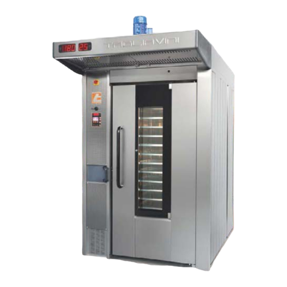
Identification Page Image of the oven Maintenance and use manual Pag. 24 COMBUSTION ROTOR 2018 Ver. 1.1 from 24/06/18... -
Page 25: Oven General Information
Oven general information GENERAL TECHNICAL CHARACTERISTICS Description Pos. Data 2 SPEED ASPIRATOR MOD. 250 Min. 950 rpm – 0.18 kW Max. delivery (RT68 - RT88 - RT810) capacity Max. 1480 rpm – 0.25 kW 1440 m³/h 2 SPEED ASPIRATOR MOD. 300 Min. -
Page 26: Oven Model Technical Data
Oven model technical data Dimmensions and mass RT 68 RT 88 RT 810 RT 812 Rif. Maximum span 1450 1640 1640 1900 Depth 1940 2120 2220 2530 Maximum height (including engines) 2680 2680 2680 2730 Hood depth range 2770 3220 3320 3630 Engine overhang at one speed... - Page 27 Dimmensions and mass RT 68H RT 88H RT 810H RT 812H Rif. Maximum span 1450 1640 1640 1900 Depth 1940 2120 2220 2530 Maximum height (including engines) 2780 2780 2780 2830 Hood depth range 2770 3220 3320 3630 Engine overhang at one speed Engine overhang at two speeds Open door overhang 1054...
- Page 28 Maintenance and use manual Pag. 28 COMBUSTION ROTOR 2018 Ver. 1.1 from 24/06/18...
- Page 29 Hood exhauster rotation possibility VPA250 Oven models RT68 - RT88 - RT810 FIG. 3 Ø175 FIG. 1 FIG. 4 Ø175 FIG. 5 FIG. 2 FIG. 6 Pag. 29...
- Page 30 Hood exhauster rotation possibility Oven model RT812 FIG. 3 Ø232 FIG. 4 FIG. 1 Ø232 FIG. 5 FIG. 2 FIG. 6 Maintenance and use manual Pag. 30 COMBUSTION ROTOR 2018 Ver. 1.1 from 24/06/18...
- Page 31 Energetic characteristics RT 68 RT 88 RT 810 RT 812 Burner power 55,8 65,1 76,7 88,4 Diesel nozzle flow (at 60°) 1,25 1,50 1,75 Diesel supply pressure Methane gas flow(H = 9,45 kWh/m Methane gas supply pressure (G20) mbar Methane gas min. and max. pressure (G20) mbar Liquid gas flow (H = 12,68 kWh/kg)
-
Page 32: Carriage Dimensions And Characteristics
Carriage dimensions and characteristics 4.4.1 Carriage dimensions and characteristics RT oven series Hook version Turntable version elevator version Hook Turntable elevator Bread or Pastry up to 60 mm (cooked) 105 mm 107 mm 104 mm Bread or Pastry up to 40 mm (cooked) 87 mm 90 mm 87 mm... - Page 33 4.4.2 Carriage dimensions and characteristics RT "H" oven series Hook version Turntable version elevator version Hook Turntable elevator Bread or Pastry up to 60 mm (cooked) 105 mm 107 mm 104 mm Bread or Pastry up to 40 mm (cooked) 87 mm 90 mm 87 mm...
- Page 34 4.4.1 Graphic verification of carriage rotation inside the oven Diagonal of a bulky carriage able to rotate in the oven. (D = , A e B are the carriage sides) 1000 1200 1400 1600 1100 1300 1500 1700 1000 1100 1200 1300 1400 1500 1600 1700 RT 680 = D max 1050 RT 880 = D max 1215 RT 810 = D max 1302 RT 812 = D max 1550...
-
Page 35: Oven Assembly
5 OVEN ASSEMBLY ATTENTION: assembly and first oven start-up must be performed by personnel qualified and authorized by the TAGLIAVINI company. During oven installation, concerned in force directives and legislation must be respected and abided, in particular the accident prevention regulations. -
Page 36: Oven Connection
6 OVEN CONNECTION 6.1 Norms, technical regulations and directives Connecting the oven to energy sources must be conducted in compliance with the rules presented below: · in force law regulations regarding technical aspects; · electricity and water supply directives and standard; ·... -
Page 37: First Start-Up (Or After Long Inactivity Periods)
7 FIRST START-UP (or after long inactivity periods) First start-up o re-ignition after a long period of inactivity After oven assembly, certain verifications should be performed such as motor correct rotation and chimney draft (for combustion ovens). First heating operation of the oven must be performed gradually, checking if flame quality is good and if fuel flow rate and draft are suitable to that oven model: with an open vapour extraction valve, raise oven temperature about 50°... -
Page 38: Start-Up
Start-up 1) Operate the wall general switch (residual current device) 2) Insert the switch port locks placed in the electric panel. 3) Press the power button (see § 8 and 9): the lower display will indicate the set temperature, editable by specific buttons and the larger display will indicate the actual room temperature (usually inferior). -
Page 39: Oven Utilisation
8 OVEN UTILISATION 8.1 Daily power-up and component use DAILY POWER-UP Power-on the oven 30-40 minutes before you start baking, due to it's considerable size. It can be performed either manually or by means of programmed ignition. Once it has been powered on, the oven will set itself to the set temperature and maintain it by turning setting coils/burner intervals. - Page 40 STEAMER The steam generator is heated by the hot air circulating in the oven. Steam production is obtained by introduc- ing water supplied by the network to a solenoid valve activated by the controller's dedicated button ( see §). Water is dispensed through a tube onto vertically arranged cast iron plates positioned in the cooking chamber's inner wall and from here it passes through all the plates until it arrives to the drain tray.
-
Page 41: Routine And Scheduled Maintenance
9 ROUTINE AND SCHEDULED MAINTENANCE The following information is intended to aid routine maintenance staff and users By routine maintenance is intended all the operations carried out periodically in order to maintain efficiency and oven overall good condition, which do not require specific preparations and as such may be performed by non-specialised staff and, therefore, also by ordinary users and/or maintainers provided that this manual's instructions are scrupulously complied with. -
Page 42: Basic Safety Standards
9.1 Basic safety standards Please read the General safety rules (§ 1.6 ) and safety instructions (§ 11) paragraphs so that the user or routine maintainer can perform routine maintenance operations in absolute safety conditions. IMPORTANT: All cleaning and maintenance interventions must be performed after: ·... - Page 43 To clean the glass inside is enough to open with the key the external crystal and so you have access to the interior of the two crystals in order to clean them easily by following the procedures mentioned above. With the external crystal is also open access to lamps and lighting on the socket and then you can proceed to a con- trol or a replacement of any components not working.
- Page 44 9.2.2 Stainless steel front side cleaning When cleaning the oven's metal front panel, except the two crankcase silk-screened parts, it is recommended that you use a stainless steel spray product that will simultaneously clean and polish the surfaces. Before cleaning the front panel columns, remove and open the two lateral silk-screen crankcases, to prevent the stainless steel product of ruining the silk screen printing.
- Page 45 9.2.5 Cleaning control units When clean the oven's control units, it is recommended that you use mild detergents and a soft cloth (do not use rough or abrasive cloths). Cleaning operations must be carried out at least once a month trying to eliminate all traces of dirt before crystallizing, N.B.
-
Page 46: Steam Extraction Hood
9.2.9 Water filter cleaning (figure below) Once every two months, or after every 500 operation hours, the frequency is variable, based on steamer utilisation and used water quality, clean the water manifold filter (F). To achieve this, remove lower blocking panel thus accessing the valve compartment where the solenoid valve manifold is located, unscrew the cap (T) and pull out the filter. -
Page 47: Carriage Lock-Down (Due To Lack Of Current Or Another Cause)
9.4 Carriage lock-down (due to lack of current or another causes). YOU MUST PAY THE UTMOST ATTENTION WHEN OPENING THE DOOR, STEAM RESIDUE LEAKAGE FROM THE COOKING CHAMBER IS POSSIBLE. It is possible to extract a carriage that was possibly locked into the cooking chamber by performing these actions: CHECK IF THE CARRIAGE'S ROTATION DIRECTION IS... -
Page 48: Steamer Failure
IF ABOVE MENTIONED INSPECTIONS ARE CARRIED OUT AND FOUND ANOMALIES PERSIST, IT WILL BE NECESSARY TO RESORT TO THE TAGLIAVINI'S SERVICE . To remove the water supply tubes, the following operations must be carried out: Unscrew the water fitting(pos. -
Page 49: Lamp Replacement
9.6 Lamp replacement The oven is equipped with interior lighting located on the main door. To replace the lamps you must: Open the external glass panel of the door via lock S using the special wrench C provided At this point you may proceed with cleaning of glasses (both outside and inside)using luke warm water, with the oven cooled... -
Page 50: General Electric Panel Access
General electric panel access DANGER OF DEATH ANY OPERATION MUST BE CARRIED OUT WITH A DISCONNECTED POWER SUPPLY 1. Unscrew the locking front screws from the main panel 2. Remove the protective crankcase fastening front bolts in order to gain access to the main electrical panel 3. -
Page 51: Motorization Group Friction Adjustment
9.8 Motorization group friction adjustment TIGHTEN USING A TORQUE WRENCH, USING TIGHTENING TORQUE (CM) INDICATED IN THE TABLE CM (Nm) Oven Model 43,0 RT812 37,2 RT810 33,7 RT88 29,6 RT68 Pag. 51... -
Page 52: Security Thermostat Adjustment And Reset
Security thermostat adjustment and reset The plastic box (A) is placed above the furnace where fumes safety thermostat (T) is located In case of fumes safety thermostat T h e f u m e s s e c u r i t y intervention;... -
Page 53: Safety
SAFETY These pages provide the information necessary to maintain system safety and prevent possible injury (the oven was designed and built by respecting the European safety standards or other countries if required). The oven should be used only by qualified personnel and instructed on its use. The furnace was built with appropriate measures in order to ensure the user's and maintenance staff's safety and health 10.1... - Page 54 The figure shows the sign with pictograms for signaling the thermal hazards due to: at the steam outlet from inside the cooking chamber when the door is opened and in absence of operation of the steam extractor. Extreme care is recommended during the opening of the door The figure shows the pictogram, silk-screened on the door glass, for signaling the dangers of a thermal nature due to the temperatures reached by the oven in the door area and in the areas inside the cooking chamber...
-
Page 55: Heat-Resistant Gloves
In burn on contact with solid parts risk operations, the operator must necessarily use appropriate P.P.E. (personal protective equipment) and devices consisting of: heat-resistant gloves. During inspections, the operator must be warned to keep an adequate safe distance avoiding to lean against the oven. When vapour escape occurs, the operator must lightly open the oven door before pulling the hot carriage from cooking chamber, allowing the aspirator to suck up the steam automatically on oven door opening, therefore definitively opening the door extract the... -
Page 56: Troubleshooting And Possible Immediate Interventions
Troubleshooting and possible immediate interventions PROBLEM CAUSE SOLUTIONS Main switch Make sure that the on/off switch and the residual current device is placed upstream of the oven, they are properly plugged in and the power sup- ply cables are connected to the oven Main protection fuses inter- Check the main protection fuse continuity and if faulty, replace... - Page 57 PROBLEM CAUSE SOLUTIONS Fan air recirculation opera- Check if the recirculating air fan (pos. 11 §12.1 ) is operational and it's rotation direction corresponds tion to the one indicated by the arrow. Operation carriage rotation Make sure the carriage rotation geared motor (pos. Uneven 10 §12.1 ) is operational and it's rotation direction geared motor...
- Page 58 PROBLEM CAUSE SOLUTIONS Steamer operation has Check if steamer operation has been disabled form the control panel been disabled form the control panel Check if the water valve is open and the water Lack of water reaches the steamer's solenoid valves Dirty filter Clean the filter on the water manifold Solenoid valve not working...
- Page 59 PROBLEM CAUSE SOLUTIONS Vapour aspirator circuit Check if the vapour aspirator circuit breaker has been tampered with or faulty; if faulty replace, if breaker tampered with or tampered with check cause before resetting. faulty Vapour aspirator contactor Check if the Vapour aspirator contactor receives The vapour aspira- input signals and if not than it's fault;...
-
Page 60: Motor Unit Hook/Platform Display
12. List of components and adjustments 12.1 Motor unit hook/platform display Maintenance and use manual Pag. 60 COMBUSTION ROTOR 2018 Ver. 1.1 from 24/06/18... - Page 61 Linguett Molla a DADO T Ingrassa Dado M ANELLO ALBERO PIGNON Pos. Descrizi Q.tà DISEGNATO / DRAWN BY MACCHINA / MA APPROVATO / APPROVED DENOMINAZIO GRUPPO R.U.T. QUOTE SENZA INDICAZIONE DI T SMUSSI NON Q Pag. 61 T.T. / FIN. preparato da: RCQ verificato ed approvato da:...
- Page 62 Maintenance and use manual Pag. 62 COMBUSTION ROTOR 2018 Ver. 1.1 from 24/06/18...
- Page 63 PLATFORM ASSEMBLY PARTICULARITIES Pag. 63...
-
Page 64: Motor Unit Elevator Display
12.2 Motor unit elevator display Maintenance and use manual Pag. 64 COMBUSTION ROTOR 2018 Ver. 1.1 from 24/06/18... - Page 65 Pag. 65...
- Page 66 Maintenance and use manual Pag. 66 COMBUSTION ROTOR 2018 Ver. 1.1 from 24/06/18...
- Page 67 Pag. 67...
-
Page 68: Motorization Particularity List
12.3 Motorization particularity list Description Code Position LIFT ENGINE BODY 005.999.7.098 LIFT ENGINE 005.999.7.082 CARRIAGE HOOK 005.999.7.012 SHAFT SUPPORT WASHER 005.999.7.058 ENGINE SPROCKET GROUP 005.999.7.113 ELEVATOR SPROCKET GROUP 005.999.7.103 HOOK ENGINE SHAFT 005.999.7.077 ENGINE-LIFT SHAFT 005.999.7.106 ENGINE-LIFT SHAFT 005.999.7.118 SENSOR SUPPORT 005.999.7.067 INDUTT.SIEMENS SENSOR 3RG4013-0KA00 M18 A0500272... - Page 69 Description Code Position BEARING 2203 E - 2RS1 - 17 x 40 x 16 A1100408 ENGINE HUB BEARING - ELEVAT. SPACER 005.999.7.119 ELEVATOR GEARED PINION 005.999.7.117 GREASER - UNI 7663 - A M10x1 A1050195 OUTLET 12x35 UNI 1707 A1760295 DOUBLE JUNCTION ADJUSTMENT PIN 0058197041 BOLT M10 UNI5588 A1650090...
-
Page 70: Micro Door And Seals
12.4 Micro door and seals Description Code Position Micro LOVATO KS A4F A5021175 Screws TBEI M6 x 12 A1620513 Door micro support XX520061 ROTOR door vertical gasket 00059994090 ROTOR door inferior gasket - RT68 0056894024 ROTOR door inferior gasket - RT88 - RT810 - RT812 0058894022 Maintenance and use manual Pag. - Page 71 Pag. 71...
-
Page 72: Fumes Extraction Hood Display (Optional)
12.5 Fumes extraction hood display (OPTIONAL) Description Code Position Hood display dashboard 005.999.1.106 Cil. spacer ø6x10 341032 Hood display A0450102 Normal bolt M3 A1650050 Hood display controller clos. cover 005.999.1.107 Flat washer UNI6592B 4.3x12 A1700135 Normal bolt M4 UNI 5588 A1670020 Serial connection cable 3 MT A0450100... - Page 73 The suction hood screen displays oven temperature and the remaining time in minutes of the cooking progress. In case the oven is in stand-by mode, the display always shows the oven's current temperature and the time displays 00. Pag. 73...
- Page 74 12.6 Water connection electrovalve - Liters counter (OPTIONAL) DESCRIPTION COD. POS. IMPURITY COLLECTOR ½” 74/A A1900310 RF SERIES LITERS COUNTER ½ M-M- 1-15 L/MIN (OPTIONAL) A0530514 REDUCED SLEEVE FF 3/4X1/2 FIG.240 A1800114 SCREW TCI M4 X 16 UNI 6107 A1600506 ELECTROVALVE SING.
-
Page 75: Door Lock
12.7 Door lock DESCRIPTION COD. POS. SUPPORT GROUP FOR LEFT COLUMN MANUAL LOCK 05999468 UNION FORKS SCREW LOCK MOVEMENT 05999412 PIN LOCK 05999404 UPPER ARM GROUP MANUAL LOCK ON LEFT COLUMN 0059994117 LOWER ARM LOCK ON LEFT COLUMN 05999461 HANDLE GROUP MANUAL LOCK ON COLUMN 05999462 MANUAL LOCK HOOK 05999463... -
Page 76: Steam Exhaust Automatic Valve (Optional)
12.8 Steam exhaust automatic valve (optional) Descrizione Codice Posizione Tubo flex alluminio ø80 A0660105 Valvola motorizzata con flangia 0059999146 Gr. scatola valvola automatica 0059999140 Rotary actuator GRUNER 341-230D-03 A0500557 Maintenance and use manual Pag. 76 COMBUSTION ROTOR 2018 Ver. 1.1 from 24/06/18... - Page 77 Manual valve handling Remove plug S Using the motorized shutter "L" lever you can open the valve bringing it from closed position "C" to open position "O", thus blocking it in this position using the "F" tab To close the valve again release the "L" lever from the "F" tab. and move it to close position "C"...
-
Page 78: Air Slot Adjustment
12.9 Air slot adjustment 12.9.1 Air slot adjustment (RT/RTE 68 model ) LOUVER Maintenance and use manual Pag. 78 COMBUSTION ROTOR 2018 Ver. 1.1 from 24/06/18... - Page 79 12.9.2 Air slot adjustment (RT/RTE 88-810 model ) LOUVER 11.5 11.5 8.5 15.5 15.5 10 10.5 10.5 10 Pag. 79...
- Page 80 12.9.3 Air slot adjustment (RT/RTE 812 model ) LOUVER Maintenance and use manual Pag. 80 COMBUSTION ROTOR 2018 Ver. 1.1 from 24/06/18...
- Page 81 Pag. 81...
- Page 82 13. Control Panel Maintenance and use manual Pag. 82 COMBUSTION ROTOR 2018 Ver. 1.1 from 24/06/18...
-
Page 83: Smart" Control Panel Description
13.1 "SMART" control panel description The control panel is fully electronically managed and contains all major management and control functions of the oven. The machine is equipped with an anti black-out device able to restore set parameters in case of a power supply failure (if before the black-out, the controller's cooking timer was enabled, when power supply is restored, the controller emits a sound similar to the one determining the end of the cooking time) . - Page 84 Description Turn on/off push-push button for cooking timer, cooking's end notice beep and possible alarms. When the controller is on and the "enter" key is pressed, the current day and date may be adjusted. When the controller is in stand-by mode and the "enter" button is pressed, the current day and time are displayed.
-
Page 85: Manual Operation
13.2 Manual operation Description Display STOP mode cooking time. Set temperature is displayed in the centre, the upper area indicates vapour exhaust valve's closed position (automatic optional) and next to the status TIMER COOKING TIME "STOP". The bottom displays 3 parameters status, from left: - Hood aspirator - Cooking chamber air recirculation speed - Cooking time set in minutes... - Page 86 Description The 3 side figures display the screens that appear when pressing the right key corresponding to the aspirator hood symbol. These figures represent aspirator status: Low velocity aspirator operation High velocity aspirator operation (when the cooking chamber's door is opened, the oven automatically turns on the aspirator at high speed.
-
Page 87: Automatic Operation (Using A Program)
13.3 Automatic operation (using a program) Description When the cooking timer is on STOP, pressing the ENTER key to enter the recipes list. Here you can select an already edited recipe or a new number for a new recipe by using the UP and DOWN arrows. - Page 88 To pass from a parameter to another press the two inferior buttons corresponding to the left and right arrows. Press ENTER to store. To add a row, press the centre key under the symbol, to change the values press the arrows next to the UP and DOWN keys.
-
Page 89: Day And Hour Set-Up
To invoke a previously set program, press ENTER, here you will enter in the recipe list by using UP or DOWN arrows to select the desired recipe and by pressing the centre button corresponding to the V symbol, the recipe is invoked. - Page 90 13.5 Programmed ignition Description In order to access the scheduled ignition section, the 2 arrow UP-DOWN keys you must pressed and held for at least 5 seconds with a shut-down controller but with a connected power supply. This screen will be accessed by pressing the key on the lower left side of the calendar figure and the cooking cham- ber scheduled ignition management section is accessed.
-
Page 91: Steam Flow Adjustment
Description To enable controller start-up conducted by the weakly schedule, with a powered off controller in stand-by, press the ENTER key and it will display Pro (see left) With a controller set to Pro or a powered-off controller, press the START/STOP button to display current time and day. -
Page 92: Level 1Setup
13.7 Level 1 set-up Description In order to access first level set-up section, the 2 arrow UP- DOWN keys you must pressed and held for at least 5 seconds with a shut-down controller but with a connected power supply (power-on/off key corresponding led turned on). This screen will be accessed by pressing the key on the lower right side of the indicated figure and the first level set-up section is accessed. - Page 93 Description Selection (03) FURNACE NUMBER. By pressing the ENTER key we can select the furnace number equipped with the controller. For more ovens sharing a serial connection (up to 32 ovens) do not assign the same number to two or more ovens as controllers with the same ID number do not exist, this would block data transmission between ovens.
- Page 94 Description Parameter 10 - PRE COOKING ALARM, by pressing the ENTER key at least one alarm may be selected to signal cooking operation end and operation time. Choose between 1 and 600 sec. (alarm enabled) or NO (alarm disabled), default value 60 sec. Parameter 12 - TEMP.
- Page 95 Description Parameter Selection 15 - ALARM VOLUME, by pressing the ENTER key we are going to select if we want the alarm volume LOW or HIGH. Parameter Selection 16 - ALARM DURATION, by press- ing the ENTER key select alarm duration between 5 an 120 seconds.
- Page 96 Description Parameter Selection 19 - DISPLAY MODE, by pressing the ENTER key select the display type that we want to have during cooking, the options are: TEMP. + TIME, by selecting this option the temperature and cooking time in minutes will be simultaneously dis- played.
- Page 97 Description Parameter Selection 23 - COOLING, by pressing the ENTER key this parameter is going to be adjusted.This parameter corresponds to a heat exchanger fan switch- off delay (in minutes) after the oven's power shut down (standby). Used for combustion cylinder cooling. Settable values from 0, …, 30 sec Default value 10 sec.
- Page 98 Description Selection parameter 28 - FREQUENCY 4 INVERTER pressing ENTER will set this parameter that corresponds to the speed 50 Hz 4, set to default: Selection parameter 29 - FREQUENCY 5 INVERTER pressing ENTER will set this parameter that corresponds to the speed 5, the highest set at 55 Hz by default: Parameter Selection 35 - MANAGEMENT TRUCK, by pressing the ENTER key this parameter is going to be...
- Page 99 Description Parameter Selection 38 - VALVE DELAY, press the ENTER key to select the time, in seconds, to leave the steam drain valve open after door closing. The settable values are: - NO Closed valve - From 5 to 30 seconds in 5 second segments default 10 seconds) Parameter Selection 42 - RECIPE TRANSFER, by pressing the ENTER key this controller will begin transmitting the...
- Page 100 Description Parameter Selection 45 - IMPORT RECIPES, by pressing ENTER key we are going to import the recipe from a USB stick that we have inserted into the USB port. Remember that only .tag files will be imported. Press the ENTER key only after you have inserted the USB key.
- Page 101 Pag. 101...
- Page 102 13.8 "SMART" controller alarm list - oven ROTOR ALARM CAUSE SOLUTIONS "ROOM P.INT." Room temperature de- Check cable tensioning. Replace tection probe connection probe interruption "P.INT/COR G.F" Cold temperature detec- Replace the power panel board tion junction probe con- nection interruption "OPEN DOOR"...
- Page 103 ALARM CAUSE SOLUTIONS "COMUNICAT. Interrupted or defective Check inverter serial connection. SERIAL INVERTER" inverter connection "INVERTER ERROR" Non operating inverter or Check inverter operation and re- inverter programming miss- place if necessary. ing. "PRESS START" Command pending oven Press the START button to start the program or cooking.
-
Page 104: Data Transfer Usb Slot
13.9 Data transfer USB slot Unscrew the plastic cap and insert the USB key into the slot taking care to insert it from the correct side, and then follow the control panel display instructions. Maintenance and use manual Pag. 104 COMBUSTION ROTOR 2018 Ver. -
Page 105: Procedure To Update The Smart Control Unit Software
13.10 PROCEDURE TO UPDATE THE SMART CONTROL UNIT SOFTWARE 1. Prepare a USB stick containing the following updated files: - Vid12_xx.bin - Rotqu_xx.bin - ELEQU_xx.bin where "xx" is the software version 2. Set the control panel in stand-by and enter the level 1 parameters (see the user manual in the "Level1 set-up"... - Page 106 As a reply, a complete price offer, delivery and sale terms will be sent to you as soon as possible. If the request is attained in another form or not completely filled in, TAGLIAVINI S.p.a. is not liable for any possible type of inconvenience. Maintenance and use manual Pag.
- Page 107 SERVICE AND SPARE PARTS OFFICE TELEFAX +39.0521.628763 - email service@tagliavini.com OFFER REQUEST FORM N°. page Machine serial number SPARE PARTS Goods delivery address Invoice delivery address Applicant name Telephone number Shipping by: Fax number Date Quantity Code number Description Pag. 107...
-
Page 108: Connection Smart Units
15 Connection SMART units Maintenance and use manual Pag. 108 COMBUSTION ROTOR 2018 Ver. 1.1 from 24/06/18... - Page 109 Pag. 109...
- Page 110 Steam extraction hood display (OPTIONAL) triple connector Maintenance and use manual Pag. 110 COMBUSTION ROTOR 2018 Ver. 1.1 from 24/06/18...
- Page 111 Pag. 111...
-
Page 112: Connection Ibake Units
16 Connection IBAKE units Maintenance and use manual Pag. 112 COMBUSTION ROTOR 2018 Ver. 1.1 from 24/06/18... - Page 113 Pag. 113...
-
Page 114: Wiring Diagram
17 Wiring diagram (this is the wiring diagram standard 400V 3) ATTENTION: ATTENTION: In the manual is inserted a standard electric diagram not necessarily this electric diagram corresponds to the oven in your possession. The original wiring diagram of the oven,to refer to, is positioned inside the electrical panel box Maintenance and use manual Pag. - Page 115 Pag. 115...
- Page 116 Maintenance and use manual Pag. 116 COMBUSTION ROTOR 2018 Ver. 1.1 from 24/06/18...
- Page 117 Pag. 117...
- Page 118 Maintenance and use manual Pag. 118 COMBUSTION ROTOR 2018 Ver. 1.1 from 24/06/18...
- Page 119 Pag. 119...
- Page 120 Maintenance and use manual Pag. 120 COMBUSTION ROTOR 2018 Ver. 1.1 from 24/06/18...
- Page 121 Pag. 121...
- Page 122 Maintenance and use manual Pag. 122 COMBUSTION ROTOR 2018 Ver. 1.1 from 24/06/18...
- Page 123 Pag. 123...
- Page 124 Maintenance and use manual Pag. 124 COMBUSTION ROTOR 2018 Ver. 1.1 from 24/06/18...
Need help?
Do you have a question about the ROTOR RT 68 and is the answer not in the manual?
Questions and answers