Table of Contents

Related Manuals for AES Corporation IntelliPro Fire 7794A

Summary of Contents for AES Corporation IntelliPro Fire 7794A
- Page 1 AES 7794A IntelliPro Fire Installation Manual AES Corporation 285 Newbury Street Peabody, MA 01960 USA Tel (978) 535-7310 • Fax (978) 535-7313 www.aes-corp.com Copyright © 2017 AES Corp. All Rights Reserved Part No. 40-7794A Rev. 3 9/20/2018...
- Page 2 AES 7794A IntelliPro Fire This page is intentionally blank. Part No. 40-7794A Rev. 3 9/20/2018...
-
Page 3: Table Of Contents
AES 7794A IntelliPro Fire Table of Contents Summary ....................6 Basic Functions ..................6 User Interface ..................6 System Knowledge Requirements ............6 Fire Alarm Control Panel Telco Interface Requirements ....6 Safety Considerations ................7 Technical Specifications ................7 Installation of 7794A ................. - Page 4 AES 7794A IntelliPro Fire Pulse Alarm format ................23 AP Input Gain ..................23 Intercept on Blind Dial ................24 Line Cut Report ..................24 POTS Cut Report Delay ................24 POTS Restoral Delay................25 6.10 AP Account Override................25 6.11 POTS Input Gain ..................
- Page 5 AES 7794A IntelliPro Fire Warranty ....................36 List of Tables Table 1. Configuration Options for AES 7794A ..........20 Table 2. Blink Patterns ................. 29 Table 3. Modem Format and Speed ............30 Table 4. Supported Bosch/Radionics Panels ..........31 Table 5.
-
Page 6: Summary
AES 7794A IntelliPro Fire Summary This document describes the installation procedure for the AES 7794A IntelliPro Fire module used with the AES 7707 or 7177 Subscriber in commercial Fire Alarm Control Panel (FACP) installations. Installed between the FACP and AES 7707 or 7177 Subscriber, the 7794A intercepts alarm panel messages and sends them to the monitoring station via the AES 7707 or 7177 Fire Subscriber Unit. -
Page 7: 1.4 Safety Considerations
AES 7794A IntelliPro Fire 1.4 Safety Considerations As part of the 7794A installation, the following safety considerations should be kept in mind: Install all equipment in accordance with the National Electric Code, National Fire Protection Association NFPA 70, NFPA 72, and local building codes. ... -
Page 8: Installation Of 7794A
AES 7794A IntelliPro Fire Installation of 7794A Equipment List The 7794A IntelliPro includes the following items: 7794A IntelliPro AES RJ11 cable 1 each AES P/N 13-0395 Hex standoffs hardware Hex nuts w/lock washer 4 each Insulating washers 2 each Installation 1. - Page 9 AES 7794A IntelliPro Fire 4. Place hex nuts over the washer on the standoffs to secure the board in the four places as shown below. Do not overtighten hex nuts. For information on connecting the fire alarm control panel PSTN wiring, refer to either the Primary Communication Interface section on page 10 or the Supplemental Communication Interface section on page 13, depending on your application.
-
Page 10: Primary Communication Interface
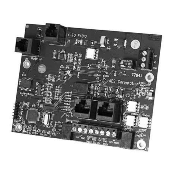
AES 7794A IntelliPro Fire Primary Communication Interface Figure 1 shows connector and diagnostic LED location on the 7794A. Figure 1. 7794A Connector and LED Locations Part No. 40-7794A Rev. 3 9/20/2018... -
Page 11: Connecting 7794A To Alarm Panel
AES 7794A IntelliPro Fire Connecting 7794A to Alarm Panel When mounted in a subscriber enclosure and connected to the Fire Alarm Control Panel dialer, the 7794A delivers alarm messages to the central monitoring station as shown in Figure 2. The 7794A is supervised by the 7707 or 7177 Subscriber, which continuously monitors a “heartbeat”... -
Page 12: Figure 3. Primary And Secondary Communications Interface
AES 7794A IntelliPro Fire Figure 3. Primary and Secondary Communications Interface To connect the 7794A to the FACP: 1. Extend FACP Dialer 1 and Dialer 2 TIP and RING to the 7794A. 2. Connect FACP Dialer 1 and Dialer 2 TIP wire to J6 terminal block labeled AP TIP (see Figure 4). -
Page 13: Supplemental Communication Interface
AES 7794A IntelliPro Fire 4. With the Primary Communication Interface wiring completed, proceed to the Configuring the 7794A. Supplemental Communication Interface Figure 5 shows connector and diagnostic LED location on the 7794A. Figure 5. Connector and LED Locations Connecting the 7794A to Alarm Panel (U. S. Installation) The diagram below displays the Fire Alarm Control Panel (FACP) with both dialers connected to the 7794A (AP TIP and AP RING). -
Page 14: Connection Details - 7794A To Alarm Panel (U.s Installation)
AES 7794A IntelliPro Fire Figure 6. 7794A to Alarm Panel (U.S. Installation) Two connection methods are used from FACP to the subscriber. The first is FACP Dialer 1 and Dialer 2 to the 7794A. The second is FACP zone outputs to 7707 or 7177 zone inputs. -
Page 15: Figure 7. Alarm Panel Connections
AES 7794A IntelliPro Fire Figure 7. Alarm Panel Connections Part No. 40-7794A Rev. 3 9/20/2018... -
Page 16: Connecting The 7794A To Alarm Panel (Canadian Installation)
AES 7794A IntelliPro Fire 2. Wire the zones of the FACP to the 7707 or 7177 as shown above in Figure 6. ! Disabling Second FACP Telco Connection ─ Most fire panels can be Important configured to disable the second Telco connection which disables panel supervision for the disabled connection. -
Page 17: Connection Details - 7794A To Alarm Panel (Canadian Installation)
AES 7794A IntelliPro Fire AP reports via Method 3. If used, 7794A-7707 or 7794A-7177 reports into MultiNet (DIALER FAILURE). Method 2 FAILS: antenna cut, etc. 7707 or 7177 engages J4 Trouble Relay J4 relay trip causes local annunciation AP reports via Dialer into Phone Receiver (RF COMMUNICATOR FAILURE) Connection Details –... - Page 18 AES 7794A IntelliPro Fire Method 3: Supplemental: RF (7794A to 7707 or 7177 ) via Dialer 1, Reverse Polarity, Other Technologies, Relays or other means provided by ULC S559 Listed FACP Normal case: Alarm = Dialer 2 dials into Phone Receiver or via Dialer 1 into MultiNet receiver Method 1 FAILS: PSTN fails (line cut, failure to connect, etc.) Reports with two messages:...
-
Page 19: Configuring The 7794A
AES 7794A IntelliPro Fire Configuring the 7794A Configuring the 7794A IntelliPro installed in the 7707 or 7177 subscriber requires a smartphone or another computer device with a web browser. The 7707/7177 subscriber must be configured and powered on. Configuration Interface The 7794A is configured through a web browser interface provided by the 7707/7177 subscriber. -
Page 20: Programming
AES 7794A IntelliPro Fire Programming Programming Options ─ UL NOTICE TO USERS NOTICE TO USERS, INSTALLERS, AUTHORITIES HAVING JURISDICTION, AND OTHER INVOLVED PARTIES This product incorporates field-programmable software. In order for the product to comply with the requirements in the Standard for Control Units and Accessories for Fire Alarm Systems, UL 864, certain programming features or options must be limited to specific values or not used at all as indicated in Table 1. -
Page 21: Phone Line
AES 7794A IntelliPro Fire Phone Line This option is set depending on whether a POTS (telephone company provided) line is connected. Option settings: Yes or No Yes = Phone line is present No = Phone line is not present (default) Important! When Phone Line is set to Yes and Line Cut is set to No, then if Phone Line is changed from Yes to No, then back to Yes, the Line Cut Report automatically... -
Page 22: Cid Alarm Format
AES 7794A IntelliPro Fire CID Alarm Format This option sets the Alarm Panel Report Format to Contact ID format. Modem Alarm Format This option sets the Alarm Panel Report Format to MODEM. When MODEM is selected, the Alarm Panel Modem Format menu selection appears: For details on selection, see “Bosch/Radionics Modem II and Modem III,”... -
Page 23: Pulse Alarm Format
AES 7794A IntelliPro Fire Pulse Alarm format This option sets the durations and frequencies for the Pulse Alarm format. The following configuration options may be set when the format is PULSE: Handshake Duration Handshake/Kissoff Frequency Center Frequency ... -
Page 24: Intercept On Blind Dial
AES 7794A IntelliPro Fire Intercept on Blind Dial This option is used when the alarm panel does not wait for a dial tone after going off- hook to dial out. When set to Yes, the 7794A will expect to receive digits as soon as the AP goes off hook. -
Page 25: Pots Restoral Delay
AES 7794A IntelliPro Fire POTS Restoral Delay POTS Restoral Delay requires that the Phone Line setting be set to Yes: POTS Restoral Delay specifies the delay time before a message is sent, indicating that the POTS phone line has changed from fault state to functional state. The restoral message transmission is delayed by the number of seconds set to ensure the phone line is stable. -
Page 26: Pots Input Gain
AES 7794A IntelliPro Fire 6.11 POTS Input Gain POTS Input Gain requires that Phone Line be set to Yes: POTS Input Gain increases the 7794A sensitivity when the 7794A is listening to activity on the telephone line. The default value is 20 dB, and reducing this value will decrease the 7794A gain. -
Page 27: Ap Output Gain
AES 7794A IntelliPro Fire 6.13 AP Output Gain Advanced Options Display must be set to Yes. AP Output Gain sets the output gain when the 7794A is in POTS emulation mode. It is used to increase the gain of the dial tone as well as the handshake and KISS-OFF tones sent by the 7794A to the AP. -
Page 28: M3 Ec Text To Cid Enabled
AES 7794A IntelliPro Fire 6.16 M3 EC TEXT to CID Enabled Note: M3 EC TEXT to CID is MODEM III Event Code Text to Contact ID. Refer to Section 6.1 Programming Options ─ UL NOTICE TO USERS Table 1. This setting enables the 7794A to scan the Modem III description field for text specific to events that are typically silent at the local site and that the dealer does not want to have sent through as a general alarm message (E140/R140). -
Page 29: Clock Frequency Shift
AES 7794A IntelliPro Fire 6.18 Clock Frequency Shift Clock Frequency Shift requires that Advanced Options be set to Yes: Clock Frequency Shift is for advanced diagnostic purposes and is generally not used. Yes: Enable No: Disable (default) Keep set at No. 6.19 Status LED Blink Patterns An LED indicator on the Model 7794A shows system status. -
Page 30: Format: Bosch/Radionics Modem Ii And Modem Iii
AES 7794A IntelliPro Fire Format: Bosch/Radionics Modem II and Modem III To configure the 7794A to process modem formats, select MODEM as the AP Report Format type (see Alarm Panel Report Format on page 21 for more details). The following table displays the modem format and speed (baud rate) settings for the Modem format. -
Page 31: Format: Pulse
AES 7794A IntelliPro Fire Table 4 lists the Bosch/Radionics panels that are supported: Table 4. Supported Bosch/Radionics Panels Panel Model Revision Number Format Tested D7412GV2 7.08 Modem III D7412GV3 8.03 Modem III D8112E1/G1 Pulse Only D8112G2 31.31 Modem II D6112 Modem II D2212B 3.03... -
Page 32: Notes On Pulse Formats
AES 7794A IntelliPro Fire Table 5 shows the corresponding values for the different parameters associated with each pulse format. Table 5. Supported Pulse Formats Pulse Format Ademco LS (10 pps) (4+2) Ademco LS (10 pps) (3+1) Ademco LS (10 pps) (4+1) Ademco LS Double Round (3+1 Expanded) Ademco HS Double Round (3+1 Expanded) Ademco Slow Silent Knight Slow, HS 1400 Hz... -
Page 33: Double Round
AES 7794A IntelliPro Fire Double Round Double round sends the same message twice and is automatically detected. This is a method used by some pulse protocols to allow a receiver, the 7794A in this case, to validate the data received. Translation of 3+1 and 4+1 to 4+2 1234 56 1234 56... -
Page 34: Testing
AES 7794A IntelliPro Fire The settings in Table 6 are recommended for common high-speed formats when the low-speed fallback is implemented. The 7794A will successfully interpret the data sent by the alarm panel over the phone dialer interface when speed is reduced. Note: These settings are only for the “fail safe”... -
Page 35: Contact Information
AES 7794A IntelliPro Fire Contact Information AES Corporation 285 Newbury Street Peabody, Massachusetts 01960 USA Website: http://www.aes-corp.com AES corporate Phone: (800) 237-6387 (800) AES-NETS USA (978) 535-7310 Fax: USA (978) 535-7313 Email: Check Website for latest email addresses 10. Revision History... -
Page 36: 12. Warranty
AES 7794A IntelliPro Fire 12. Warranty OWNER WARRANTY - AES CORPORATION LIMITED PRODUCT WARRANTY AND TECHNOLOGY LICENSE LIMITED PRODUCT WARRANTY: AES warrants to the original purchaser that the AES Subscriber Unit will be free from defects in material and workmanship under normal use and service for three (3) years from the date of original purchaser's purchase.
Need help?
Do you have a question about the IntelliPro Fire 7794A and is the answer not in the manual?
Questions and answers