Table of Contents
Advertisement
Quick Links
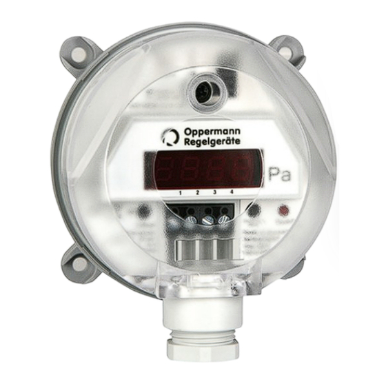
Pressure differential
transmitter DDS-AR984...
DDS-QR984...
DDS-AR984...: 2 sensor ranges, automatic zero point setting
DDS-QR984...: 8 sensor ranges, automatic zero point setting
Function
Pressure differential transmitters of type series DDS 984 are
used to measure differential, positive, and negative pressure
in gaseous, non-aggressive media. They have up to 8 sensor
pressure ranges and 2 output signals that can be selected
alternatively by swapping a jumper.
The pressure transducer converts the mechanical pressure value
into an electrical sensor signal. The piezo-resistive pressure
transducer integrated into the DDS 984 pressure differential
transmitter is configured so that the pressure to be read is
applied to a thin mono-silicon membrane. This deflects the
membrane. The membrane is equipped with resistors based
on semi-conductor technology. These detect the mechanical
deflection and generate an electrical output signal. The arran-
gement of the resistors at the same time results in temperature
response compensation. High-gain process amplifiers convert
the signal from the pressure transducer into the output signal.
The electrical output signal changes proportionally to the
applied pressure within the specified error limits.
Possible applications include:
•
Building automation, air-conditioning and cleanroom
technology
•
Valve and damper control
•
Filter, ventilator, and blower monitors
•
Airflow controls
•
Automatic zero point setting
•
Up to 8 sensor ranges
•
Metric cable glands
•
Arbitrary installation orientation
•
Output can be toggled between square root
extraction/lin.
Technical Data
Compressed medium:
Air and non-aggressive media
Power supply:
22 – 30 V AC/DC
Output signal:
0 – 10 V or 4 – 20 mA
Maximum current draw:
•
Without display
160 mA
•
With LED display
210 mA
Admissible ambient
conditions:
-10 - 50 °C, 0 - 95 % RH
(non-condensing)
Long-term stability, type: n. a.
Load (at 4 – 20 mA):
20 – 500 Ω
Linearity (incl. hysteresis
and reproducibility):
≤ ± 0,5% of full scale, min ± 1 Pa
Uncertainty (total error
excluding long-term and
temperature influence): ± 1% of full scale, min ± 1 Pa
Switching output (npn): max. 30 V DC/100 mA
Output signal toggle:
Linear/square root extraction
Zero setting adjustment: Automatic
Response time settings: Short, 200 ms
Long, 1 s (default state)
Process ports:
6 mm hose fittings
Electrical connection:
Screw terminals for wires
and cores up to 1.5 mm²
Mounting:
Screw mounted with
sheetmetal screws
Display, optional:
Red LED display, 3.5 characters
Housing material:
Switch housing with process port P2,
ABS, light-gray;
Mounting bracket with process port
P1, POM, white
Housing dimensions:
approx. Ø 85 mm, H 58 mm
Weight:
approx. 150 g
Protection type iaw.
EN60529:
IP 54 with protective cover
Cable grommet for
protective cover:
M 16 x 1,5 Polyamide threads
Standards / conformity: EN 60770, EN 61326
2011/65/EU (RoHS)
Sensor method:
Piezo-resistive pressure transducer
Sensors PG1 | Data sheet No. 13252 | Version 09-2019 | 1 | 6
Advertisement
Table of Contents

Related Manuals for Oppermann Regelgeräte DDS-AR984 Series


Summary of Contents for Oppermann Regelgeräte DDS-AR984 Series
- Page 1 Pressure differential • Automatic zero point setting • Up to 8 sensor ranges transmitter DDS-AR984... • Metric cable glands DDS-QR984... • Arbitrary installation orientation • Output can be toggled between square root extraction/lin. Technical Data Compressed medium: Air and non-aggressive media Power supply: 22 –...
- Page 2 Pressure differential transmitter DDS-AR984... / DDS-QR984... Type name Type 2 sensor ranges, automatic zero point setting Q 8 sensor ranges, automatic zero point setting M16 cable glands Sensor range: see table „Pressure ranges“ Standard: Unit of measure: Pa Standard configuration: Output signal: 0 – 10 V or 4 – 20 mA. Output can be toggled between linear/square root extraction With npn switching output. Display without display with LED display...
- Page 3 Pressure differential transmitter DDS-AR984... / DDS-QR984... Installation Terminal assignment, Klemmenbelegung 3-wire version 3-Leiter-Ausführung All work (such as installation, electrical connection, startup, operation, and maintenance) must only be performed by suf- Load ficiently qualified tradesmen. The respectively applicable local rules and regulations (e.g. national building codes, electrical/ VDE regulations, etc.) must be observed.
- Page 4 Pressure differential transmitter DDS-AR984... / DDS-QR984... Configuration pressure range pressure range Pos. DDS-QR984.5.4.3.K.1 DDS-QR984.5.5.3.K.1 Test 0 V / 4 mA Test 0 V / 4 mA 0 – 100 Pa ± 100 Pa Rotating switch for sensor range (only Type DDS QR984 ...) 0 –...
- Page 5 Pressure differential transmitter DDS-AR984... / DDS-QR984... Programming (versions with display) Sensors PG1 | Data sheet No. 13252 | Version 09-2019 | 5 | 6...
- Page 6 Masszeichnungen Masszeichnungen ø10 ø 4.5 Masszeichnungen Pressure differential transmitter DDS-AR984... / DDS-QR984... Kanalans Dimensioned drawing Climaset Befestigungswinkel 6401 Befestigungswinkel 6402 ® 984 mit Kabelverschraubung M16x1,5 984 mit Kabelverschraubung M16x1,5 984 mit Kabelverschraubung M16x1,5 Befestigungswinkel 6481 Befestigun DDS...984... Mounting bracket 6481 ø...
Need help?
Do you have a question about the DDS-AR984 Series and is the answer not in the manual?
Questions and answers