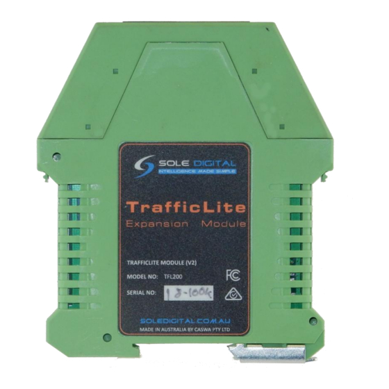
Summary of Contents for Sole Digital TrafficLite TFL200
- Page 1 TRAFFICLITE EXPANSION MODULE Model TFL200, Version 2 Installation and User Manual Revision 01 – January 2019 © CASWA Pty Ltd – 2018...
- Page 2 CONTENTS OVERVIEW ..........................3 SPECIFICATIONS ........................3 2.1 Physical Specifications ......................3 2.2 Electrical Specifications ......................4 INSTALLATION DETAILS ......................4 3.1 Prior to Installation ......................... 4 3.2 Wiring Diagrams ........................5 COMMISSIONING DETAILS ....................5 4.1 Setting set points ........................6 4.1.1 Setting up for traffic light display ................
- Page 3 1 OVERVIEW TrafficLite is an add-on module for Liftlog and MaxOut and provides 3 additional output relays. It can be used for controlling traffic lights, limiting high speed motion at high loads, and slack rope detection. Nb, TrafficLite REQUIRES a MaxOutDX, or LiftlogDX to work, it has no load sensing functions. 2 SPECIFICATIONS 2.1 Physical Specifications Overall length (mm):...
- Page 4 2.2 Electrical Specifications Parameter Description Units Supply voltage Supply current Max voltage for switch output V AC fault Max current sink by switch output fault Pfault Max contactor inrush rating at 48V Note1 Allowable operating temperature °C Note1: Extended operation at maximum temperature will reduce the life the device. 3 INSTALLATION DETAILS 3.1 Prior to Installation Before installing your TrafficLite device visually inspect the device and check that:...
- Page 5 3.2 Wiring Diagrams TrafficLite should be installed next to the MaxOut or Liftlog that will be controlling it. The maximum length of cable between the units should not exceed 200mm Figure 3: Connecting to Liftlog or MaxOut 4 COMMISSIONING DETAILS TrafficLite is set up when you configure the Liftlog or MaxOut that it is connected to.
- Page 6 4.1 Setting set points On the configuration screen there are three configurable set points. Figure 4: Set points Enter the load for each set point in Kg or Lb and set the swtich to be normally open or closed. 4.1.1 Setting up for traffic light display For switching indicator lights (or sirens) the switches should be configured normally open.
- Page 7 Figure 6: Settings for speed limiting In this example the high speed function would drop out at 9000Kg 4.1.3 Setting up for slack rope detection Connect one of the relays in series with the control signal to the down contactor and set the set point to 0Kg Figure 7: Settings for slack rope detection Nb for slack rope detection to work reliably the unit must see at least a 5% change in load when the...
- Page 8 4.2 The Status LEDS Your TrafficLite has three indicators on the front panel. Each indicates the status of each output. Colour Status Communications error GREEN CLOSED BLUE OPEN 8 | Page © CASWA Pty Ltd – 2014...

Need help?
Do you have a question about the TrafficLite TFL200 and is the answer not in the manual?
Questions and answers