Table of Contents
Advertisement
Quick Links
Revised 11/18
TECHNICAL INFORMATION FOR TGS5141-P00
Technical Information for Carbon Monoxide Sensors
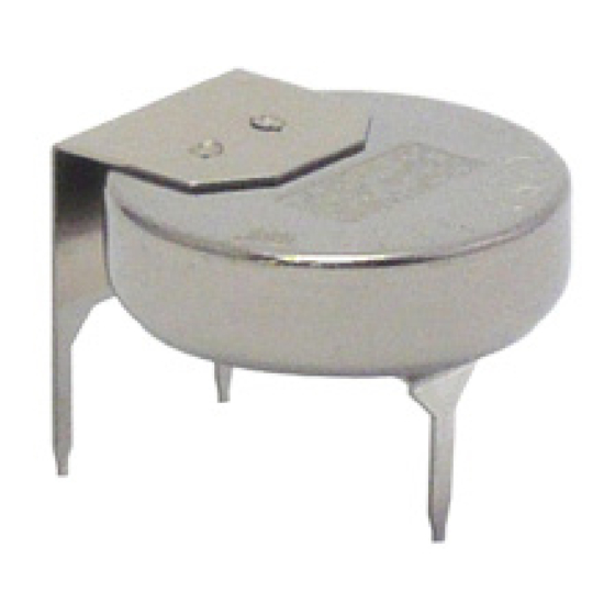
Figaro's TGS5141 is a battery operable
electrochemical sensor which uses a unique
electrolyte that eliminates the need for a water
reservoir. By eliminating the water reservoir used
in TGS5042, the comparative size of TGS5141 is
reduced to just 10% of TGS5042. With its ultra
compact size, this sensor is the ideal choice for
size oriented applications such as portable CO
detectors, small residential CO detectors, and
multi-sensor fire detectors. OEM customers
will find individual sensor data printed on each
sensor in bar code form, enabling users to skip
the costly gas calibration process and allowing
for individual sensor tracking.
Features..................................................................................................2
Applications...............................................................................................2
Structure...........................................................................................2
Basic Measuring Circuit...........................................................................2
Operating Conditions & Specifications...................................................3
Dimensions...................................................................................................3
Operation Principle......................................................................................................4
Sensitivity to Various Gases............................................................5
Temperature and Humidity Dependency.............................................5
Gas Response Pattern.................................................................................6
Repeatability.............................................................................6
Influence of Storage...................................................................................6
Normal Operation Test.....................................................................................7
Sensitivity Test...................................................................................7
Interference Gas Test......................................................................................8
Long-Term Stability................................................................................9
Corrosion Test...........................................................................................9
Variable Ambient Temperature Test................................................................9
Humidity Test.............................................................................................10
Stability Tests..................................................................................................11
Dust Test................................................................................................12
Marking..........................................................................................................................12
Cautions.......................................................................................................13
Appendix - Lead configuration............................................................................14
IMPORTANT NOTE: OPERATING CONDITIONS IN WHICH FIGARO SENSORS ARE USED WILL VARY
WITH EACH CUSTOMER'S SPECIFIC APPLICATIONS. FIGARO STRONGLY RECOMMENDS CONSULT-
ING OUR TECHNICAL STAFF BEFORE DEPLOYING FIGARO SENSORS IN YOUR APPLICATION AND,
IN PARTICULAR, WHEN CUSTOMER'S TARGET GASES ARE NOT LISTED HEREIN. FIGARO CANNOT
ASSUME ANY RESPONSIBILITY FOR ANY USE OF ITS SENSORS IN A PRODUCT OR APPLICATION FOR
WHICH SENSOR HAS NOT BEEN SPECIFICALLY TESTED BY FIGARO.
TGS5141 is a UL recognized component in accordance with the
requirements of UL2034. Please note that component recognition
testing has confirmed long term stability in 15ppm of carbon monoxide;
other characteristics shown in this brochure have not been confirmed by
UL as part of component recognition.
P a g e
1
Advertisement
Table of Contents

Related Manuals for Figaro TGS5141-P00

Summary of Contents for Figaro TGS5141-P00
-
Page 1: Table Of Contents
Marking..........................12 Cautions.......................13 Appendix - Lead configuration................14 IMPORTANT NOTE: OPERATING CONDITIONS IN WHICH FIGARO SENSORS ARE USED WILL VARY WITH EACH CUSTOMER’S SPECIFIC APPLICATIONS. FIGARO STRONGLY RECOMMENDS CONSULT- ING OUR TECHNICAL STAFF BEFORE DEPLOYING FIGARO SENSORS IN YOUR APPLICATION AND, IN PARTICULAR, WHEN CUSTOMER’S TARGET GASES ARE NOT LISTED HEREIN. FIGARO CANNOT ASSUME ANY RESPONSIBILITY FOR ANY USE OF ITS SENSORS IN A PRODUCT OR APPLICATION FOR WHICH SENSOR HAS NOT BEEN SPECIFICALLY TESTED BY FIGARO. -
Page 2: Specifications
The sensor generates a minute electric current which is Figure 2 - Basic measuring circuit converted into sensor output voltage (Vout) by an op-amp/ (Including equivalent circuit) resistor (R ) combination. Figaro recommends the following electrical parts: R1 : 1MΩ C1 : 1µF IC : AD708 Item Specification... -
Page 3: Dimensions
TECHNICAL INFORMATION FOR TGS5141-P00 1-6 Dimensions (see Fig. 3) Top view Gas inlet 8.5±0.2 Working electrode Side view 5.0±0.4 Counter electrode 13.9±0.4 Bottom view unit: mm Figure 3 - Dimensions All sensor characteristics shown in this brochure represent typical characteristics. Actual characteristics vary from sensor to sensor and from production lot to production lot. -
Page 4: Operation Principle
TECHNICAL INFORMATION FOR TGS5141-P00 2. Operation Principle Working electrode (Anodic reaction) CO + H2O → CO2 + 2H+ + 2e- (equation 1) The operation principle of TGS5141 is basically identical to that of a fuel cell. When CO passes Counter electrode (Cathodic reaction) 2H+ + 1/2 O2 + 2e- →... -
Page 5: Basic Sensitivity Characteristics
TECHNICAL INFORMATION FOR TGS5141-P00 3. Basic Sensitivity Characteristics 3-1 Sensitivity to various gases Ethanol Figure 6 shows the sensor’s sensitivity to various Iso-butane gases. The Y-axis shows output current (Iout/µA) in each gas. The output current is linear to CO concen- tration, with a deviation of less than ±5% in the range... -
Page 6: Gas Response Pattern
TECHNICAL INFORMATION FOR TGS5141-P00 3-3 Gas response pattern Figure 8 shows the gas response pattern of the CO 400ppm output signal when the sensor is placed into 30, 70, 150 and 400ppm of CO and then returned to normal air. The response time to 90% of the saturated signal level is within 60 seconds, and the recovery of the Iout(µA) -
Page 7: Normal Operation Test
TECHNICAL INFORMATION FOR TGS5141-P00 3-6 Normal operation test CO 600ppm Figure 11a shows the result of the “Normal Operation Test” required by UL2034 where the sensor is exposed to 600ppm of CO for 12 hours at 20˚C/40%RH. Stable output current signal can be seen throughout the exposure. -
Page 8: Reliability
TECHNICAL INFORMATION FOR TGS5141-P00 In addition, Figure 12b indicates the CO sensitivity characteristics of the sensor before, during, and after the Sensitivity Test, demonstrating the excellent reproducibility of TGS5141's CO sensitiv- ity characteristics. Before During After Iout(µA) 4. Reliability CO concentration (ppm) Tests conducted in this section demonstrate that TGS5141 Fig. -
Page 9: Long-Term Stability
TECHNICAL INFORMATION FOR TGS5141-P00 4-2 Long-term stability ave. min. max. Figure 14 shows long-term stability data for TGS5141. Test samples were stored in natural clean air under a short-circuit condition and measured at various intervals as dictated by the standard test N=10 conditions of UL2034. -
Page 10: Humidity Test
TECHNICAL INFORMATION FOR TGS5141-P00 (2) Effect of shipping and storage To verify the effects of shipping and storage, the sensor was tested under the conditions of UL2034. Test samples in a short-circuited condition were subjected to 70˚C for 24 hours, allowed to cool to room temperature for 1 hour, subjected to -40˚C... -
Page 11: Stability Tests
TECHNICAL INFORMATION FOR TGS5141-P00 4-6 Stability test (1) False alarm test To show the sensor’s behavior under continuous low level exposure to CO, samples were tested against the procedure detailed in UL2034--Stability Test. Test samples were exposed to 30ppm of CO continuously for a period of 30 days under standard circuit conditions. -
Page 12: Dust Test
TECHNICAL INFORMATION FOR TGS5141-P00 Dust test To judge the effect of dust contamination on TGS5141, approximately 2 ounces (0.06 kg) of cement dust, capable of passing through a 200 mesh screen, was circulated for 1 hour by means of a blower, enveloping the sensor in the test chamber. -
Page 13: Cautions
Figaro USA Inc. and the manufacturer, Figaro Engineering 6) Contact with water Inc. (together referred to as Figaro) reserve the right to make Sensor characteristics may be changed due to soaking or changes without notice to any products herein to improve splashing the sensor with water. -
Page 14: Appendix - Lead Configuration
TECHNICAL INFORMATION FOR TGS5141-P00 APPENDIX TGS5141-P00 Lead Configuration 13.9±0.4 Leads are connected to sensor electrodes when the sensors are shipped. Top View Side View Stainless steel (SUS) pin version (Fig. 22) Solid SUS pins enable the sensor to be more easily 4.15±0.40... - Page 15 TECHNICAL INFORMATION FOR TGS5141-P00 FIGARO GROUP HEAD OFFICE OVERSEAS Figaro Engineering Inc. Figaro USA Inc. Figaro Sensor (Shanghai) Co., Ltd 1-5-11 Senba-nishi 121 S. Wilke Rd. Suite 300 Room No. 1003-1004A 511 Weihai Road Mino, Osaka 562-8505 JAPAN Arlington Heights, IL 60005 USA Shanghai 200041 CHINA Tel.: (81) 72-728-2561...
Need help?
Do you have a question about the TGS5141-P00 and is the answer not in the manual?
Questions and answers