
Related Manuals for Samsung M1833NR


Summary of Contents for Samsung M1833NR
-
Page 1: Table Of Contents
MICROWAVE OVEN M1833NR SERVICE Manual MICROWAVE OVEN CONTENTS 1. Precaution 2. Specifications 3. Operating Instructions 4. Disassembly and Reassembly 5. Alignment and Adjustments 6. Troubleshooting 7. Exploded Views and Parts List 8. P.C.B Diagrams 9. Schematic Diagrams... - Page 2 © Samsung Electronics Co., Ltd. January 2005 This Service Manual is a property of Samsung Electronics Co.,Ltd. Printed in Korea Any unauthorized use of Manual can be punished under applicable Code No. : DE68-03697A International and/or domestic law.
- Page 3 PRECAUTIONS TO BE OBSERVED BEFORE AND DURING SERVICING TO AVOID POSSIBLE EXPOSURE TO EXCESSIVE MICROWAVE ENERGY (a) Do not operate or allow the oven to be (c) Before turning on microwave power for operated with the door open. any service test or inspection within the (b) Make the following safety checks on microwave generating compartments, all ovens to be serviced before activat-...
-
Page 4: Precaution
1. Precaution Follow these special safety precautions. Although the microwave oven is completely safe during ordinary use, repair work can be extremely hazardous due to possible exposure to microwave radiation, as well as potentially lethal high voltages and currents. 1-1 Safety precautions ( 1. - Page 5 1-2 Special Servicing Precautions (Continued) 17. When checking the continuity of the witches or NOTE : Connect the oven to a 20A. When transformer, always make sure that the power is Connecting the oven to a 15A, make OFF, and one of the lead wires is disconnected. Sure that circuit breaker can operate.
-
Page 6: Specifications
2. Specifications 2-1 Table of Specifications TIMER 99 MINUTES 90 SECONDS POWER SOURCE 220V 50Hz, AC POWER CONSUMPTION MICROWAVE : 1,150W OUTPUT POWER FROM 100 TO 800W (IEC-705 TEST PROCEDURE) OPERATING FREQUENCY 2,450MHz MAGNETRON OM75S(31)ESS COOLING METHOD COOLING FAN MOTOR OUTSIDE DIMENSIONS 489mm(W) x 275mm(H) x 361mm(D) OVEN DIMENSIONS... -
Page 7: Operating Instructions
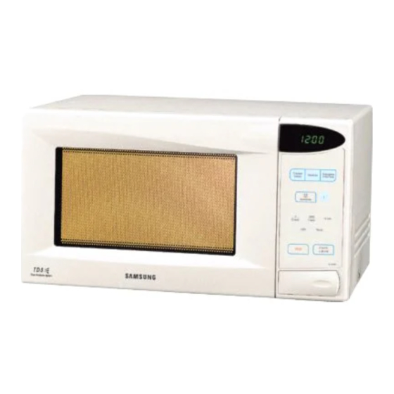
3. Operating Instructions 3-1 Control Panel 3-2 Features & External Views VENTILATION HOLES LIGHT DISPLAY CONTROL PANEL COUPLER OPEN DOOR TURNTABLE ROLLER RING PUSH BUTTON DOOR SAFETY DOOR LATCHES INTERLOCK HOLES - 4 -... -
Page 8: Disassembly And Reassembly
4. Disassembly and Reassembly 4-1 Replacement of Magnetron, Motor Assembly and Lamp Remove the magnetron including the shield case, permanent magnet, choke coils and capacitors (all of which are contained in one assembly). 1. Disconnect all lead wires from the magnetron and lamp. 2. - Page 9 4-3 Replacement of Door Assembly 4-3-1 Removal of Door “C” Insert flat screwdriver into the gap between Door “A” and Door “C” to remove Door “C”. Be careful Door "A" when handling Door “C” because it is fragile. Then remove the door assembly. Door "C"...
- Page 10 4-3-4 Reassembly Test After replacement of the defective component parts of the door, reassemble it and follow the instructions below for proper installation and adjustment so as to prevent an excessive microwave leakage. 1. When mounting the door to the oven, be sure to adjust the door parallel to the bottom line of the oven face plate by moving the upper hinge and lower hinge in the direction necessary for proper alignment.
- Page 11 4-6 Replacement of Control Circuit Board 4-6-1 Removal of Control Box Assembly 1. Disconnect the connectors from the control box assembly. 2. Remove screws securing the control box assembly. 3. Remove the knobs of the control box A’ssy. 4. Remove the screw securing the timer. SCREWS CONTROL-BOX 4-6-2 Removal of P.C.B Assembly...
-
Page 12: Alignment And Adjustments
5. Alignment and Adjustments PRECAUTION 1. High voltage is present at the high voltage terminals during any cook cycle. 2. It is neither necessary nor advisable to attempt measurement of the high voltage. 3. Before touching any oven components or wiring, always unplug the oven from its power source and discharge the high voltage capacitor. - Page 13 5-4 High Voltage Capacitor 1. Check continuity of the capacitor with the meter set at the highest resistance scale. 2. Once the capacitor is charged, a normal capacitor shows continuity for a short time, and then indicates 9MΩ. 3. A shorted capacitor will show continuous continuity. 4.
- Page 14 5-8 Output Power of Magnetron CAUTION MICROWAVE RADIATION PERSONNEL SHOULD NOT ALLOW EXPOSURE TO MICROWAVE RADIATION FROM MICROWAVE GENERA- TOR OR OTHER PARTS CONDUCTING MICROWAVE ENERGY. The output power of the magnetron can be measured by performing a water temperature rise test. Equipment needed : * Two 1-liter cylindrical borosilicate glass vessel (Outside diameter 190 mm) * One glass thermometer with mercury column...
- Page 15 5-10 Procedure for Measurement of Microwave Energy Leakage 1. Pour 275 15cc of 20±5°C(68±9°F) water in a beaker which is graduated to 600cc, and place the beaker in the center of the oven. 2. Start to operate the oven and measure the leakage by using a microwave energy survey meter.
-
Page 16: Troubleshooting
6. Troubleshooting WARNING FOR HIGH VOLTAGE 4000 VOLT EXIST AT THE HIGH VOLTAGE AREA. DO NOT OPERATE THE OVEN WITH CABINET PARTS REMOVED. DO NOT REMOVE THE CABINET PARTS IF THE POWER SUPPLY CORD IS PLUGGED IN THE WALL OULET. UNPLUG THE POWER CORD BEFORE SERVICING. 6-1 Electrical Malfunction SYMPTOM CAUSE... - Page 17 6-1 Electrical Malfunction(continued) SYMPTOM CAUSE CORRECTIONS Oven lamp and fan motor 1. Misadjustment or loose wiring of pri- Adjust door and latch switches. turn on mary latch switch 2. Defective primary latch switch Oven can program but 1. Open or loose wiring of secondary Adjust door and interlock switches.
-
Page 18: Exploded Views And Parts List
7. Exploded Views and Parts List 7-1 Exploded Views D006 D004 D005 D003 M001 D002 M019 M017 M015 M030 D007 M022 D011 W002 D049 M020 M036 C005 M051 M099 M049 M035 B006 C009 C003 B001 M037 M048 M038 B002 B018 C004 C006 B009... - Page 19 7-2 Main Parts List Code No. Description Specification Q’ty Remark B001 3405-001034 SWITCH-MICRO 125/250VAC,16A,200GF,SPST-N PRI,SEC B002 3405-001032 SWITCH-MICRO 125/250VAC,16A,200GF,SPDT B006 DE72-00138A BODY-LATCH PP WHT NC2000 0.6/0.8/1.2 B009 DE66-00088A LEVER-SWITCH NC2000(0.6/0.8/1.2),PP,-,-, B018 DE96-00115C ASSY BODY LATCH CE2611N,NC2000(BUTTON) M001 DE70-00184A PANEL-OUTER SECC T0.5 MW850WA 0.8 M015 DE39-00224A ASSY POWER CORD...
- Page 20 7-3 Control & Door Parts List Code No. Description Specification Q’ty Remark C003 RCS-22LED-12 ASSY PCB PARTS M1733R,230V50Hz C004 DE34-00062V SWITCH MEMBRANE NEW M1833NR/BWT,-,-,PET, C005 DE72-70210A CONTROL-PANEL MW779BW(3RD-0.7),ABS,-,-,- C006 DE61-70076A SPRING-BUTTON -,HSWR,PI0.6,PI0.6,-,-,-,- C007 DE66-20281A BUTTON-PUSH 3RD-W B DESIGN,-,T2x37x86,-, C009 DE67-40175A...
- Page 21 7-4 Standard Parts List Code No. Description Specification Q’ty Remark DE60-30016A NUT-FLANGE M4,MSWR10,-,-,-,-,-,-,- FAN MOTOR DE60-10082I SCREW-A -,-,-,-,2S-4X12,FEFZY,-,-,-,- B.LATCH DE60-10082I SCREW-A -,-,-,-,2S-4X12,FEFZY,-,-,-,- B.PLAT DE60-10082I SCREW-A -,-,-,-,2S-4X12,FEFZY,-,-,-,- C.AIR DE60-10082I SCREW-A -,-,-,-,2S-4X12,FEFZY,-,-,-,- C.BOX DE60-10082I SCREW-A -,-,-,-,2S-4X12,FEFZY,-,-,-,- CVT TCO DE60-10082I SCREW-A -,-,-,-,2S-4X12,FEFZY,-,-,-,- PANEL OUTER DE60-10051A SCREW-TAP PH -,-,MSWR,-,PH,M4,-,L6,-,-...
- Page 22 8-2 P.C.B Parts List Code No. Description Specification Q’ty Remark 0204-001118 FLUX SV-95-1F,C19H29COOH,C3H7OH,-,1 1.33 0401-001083 DIODE-SWITCHING MM4148,100V,150MA,LL-34,TP D07,D08,D10~D19 0402-001080 DIODE-RECTIFIER GF1G,400V,1A,DO,TP D01~D03 0402-001298 DIODE-BRIDGE DF06S,600V,1A,SMD-4,TP DF01 0403-001288 DIODE-ZENER ZMM55C5V1,4.8-5.4V,500MW,LL-34,TP ZD01 0501-000465 TR-SMALL SIGNAL MMBT3904,NPN,350mW,SOT-23,TP,30-300 TR04 0504-001008 TR-DIGITAL RN2427,PNP,200MW,2.2K/10K,SOT-23,TP TR05~TR09 0504-001080 TR-DIGITAL KRC246S,NPN,200mW,2.2K/10K,SOT-23,TP TR01~TR03,TR10...
- Page 23 8. P.C.B Diagrams 8-1 P.C.B Diagrams ( This Document can not be used without Samsung’s authorization ) - 19 -...
- Page 24 9. Schematic Diagrams 9-1 Schematic Diagrams ( This Document can not be used without Samsung’s authorization ) ASSY NOISE FIL TER MGT TCO, CAVITY TCO PRIMAR Y S/W H.V.TRANS 230V MONITOR POWER CORD H.V.FUSE 230~50Hz (0.75A) H.V.C INRUSH RELA Y P.T.C...
Need help?
Do you have a question about the M1833NR and is the answer not in the manual?
Questions and answers