Table of Contents
Advertisement
Keep this manual to hand and in good condition for future reference!
Please read this operating manual carefully before using the machine!
Translation of the original operating instructions
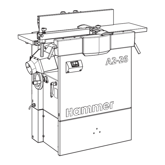
A2-26
Planer thicknesser
Download your local language
http://fg.am/ba-manuals
Operating instructions
CZ
DA
DE
EN
FR
HU
IT
NL
RO
RU
SV
511010-901, 1, en_GB
ES
PL
Advertisement
Table of Contents

Related Manuals for Hammer A2-26


Summary of Contents for Hammer A2-26
- Page 1 A2-26 Planer thicknesser Download your local language http://fg.am/ba-manuals Keep this manual to hand and in good condition for future reference! Please read this operating manual carefully before using the machine! Translation of the original operating instructions Operating instructions 511010-901, 1, en_GB...
- Page 2 FELDER KG KR-Felder Straße 1, 6060 HALL in Tirol, AUSTRIA Telephone: +43 5223 5850 0 Email: info@felder-group.com Internet: www.felder-group.com © 2022...
-
Page 3: Table Of Contents
A2-26 Table of contents Table of contents Information about the manual.......... - Page 4 Table of contents Safety devices............5.5.1 Safety limit switches.
- Page 5 A2-26 Table of contents Use..............56 Switch on / switch off / shutdown due to an emergency stop.
- Page 6 Table of contents 12.3 Spare parts list............86 12.4 Circuit diagram.
-
Page 7: Information About The Manual
A2-26 Information about the manual Information about the manual Symbol legend Safety instructions Safety instructions in this manual are indicated with symbols. The safety instruc- tions are introduced by key words which state in words the extent of the hazard. -
Page 8: Copyright
Information about the manual Copyright ● This instruction manual is to be treated as confidential. It is intended solely for those people who are to work on or with the machine. ● All descriptions, texts, drawings, photos and other depictions are protected by copyright and other commercial laws. -
Page 9: Safety Instructions
A2-26 Safety instructions Safety instructions Intended use ● The machine described in this manual is intended solely for the processing of wood, synthetic materials, and similar machinable materials. Operational safety is only guaranteed when the machine is used for the intended pur- poses. -
Page 10: Requirements Of The Personnel
Safety instructions Requirements of the personnel ● Only authorised and trained personnel may work on and with the machine. "Qualified personnel" is a term that refers to those who – due to their professional training, know-how, experience, and knowledge of relevant reg- ulations –... -
Page 11: Mandatory Safety Equipment
A2-26 Safety instructions Please note It is prohibited to wear gloves whilst working with the machine. It is only allowed to wear gloves whilst carrying out tool changes and maintenance work. 2.6.2 Mandatory safety equipment When working on or with the machine, the following must always be worn by... - Page 12 Safety instructions ● Before switching on the machine, always check to make sure that there are no other persons in the immediate vicinity of the machine. ● In the event of power supply failure, the machine will coast to a stop without applying the brakes (no electric brake action).
-
Page 13: Transport, Setup, Installation And Disposal
A2-26 Safety instructions 2.7.1 Transport, setup, installation and disposal Improper transport Improper transport can cause the machine to tilt or fall. This can cause severe crushing. ● Carry out transport according to the specifications in this instruction. ● Move unauthorised people out of the area. -
Page 14: Operate
Safety instructions Indirect touch with residual currents Deadly electric shocks ● Equip the machine's supply line with a fault-current circuit breaker. 2.7.2 Operate Improper operation Serious injuries ● Machine may only be operated by authorised, trained personnel who are familiar with how to operate the machine and are in strict observance of all safety instructions. -
Page 15: Maintain And Troubleshoot
A2-26 Safety instructions Surpassing or falling below the allowed ambient temperature Surpassing or falling below the allowed temperatures can cause malfunctions of the machine and unpredictable machine movements, which can lead to severe personal and material damage. ● Only operate machine within the listed temperature range. -
Page 16: Foreseeable Misuses
Safety instructions Improper maintenance Serious injuries ● Machine may only be maintained by authorised, trained personnel who are familiar with how to operate the machine and are in strict observance of all safety instructions. ● If possible, only perform maintenance work when the machine is discon- nected from all energy sources and an unintentional restart is prevented. - Page 17 A2-26 Safety instructions ● Placing objects or tools on the work surface. ● Use of tools or materials which are not intended for processing on the machine. ● Inserting tools that are either not allowed, or not authorised in the machine.
-
Page 18: Declaration Of Conformity
KR-Felder-Straße 1 6060 Hall in Tirol Product designation Planer thicknesser Manufacturer Hammer Model type A2-26 The following EC guidelines were applied 2006/42/EC 2014/30/EC The following harmonised norms were applied EN ISO 19085-1 EN ISO 19085-7 The prototype test was carried out by TESTPLUS TEKNİK KONTROL ve BELGELENDİRME... - Page 19 A2-26 Declaration of Conformity UKCA - Declaration of Conformity Declaration of Conformity according to UK Directive S.I. 2008/1597 Machine number reference: The machine number is printed on the cover sheet of the operating manual. We hereby declare that the machine indicated below, which corresponds to the design and construction of the model we placed on the market, conforms with the health and safety requirements as stated by the UK guidelines (see table).
-
Page 20: Technical Information
Technical information Technical information Dimensions and weight D max. D min. Fig. 1: Dimensions A2-26 Basic machine Data Value Unit Space requirement A x B 690 x 440 mm Total height C (Planing) 910 mm Total height C1 (Thickness planing) 1300 mm Total width D min. -
Page 21: Operation And Storage Conditions
A2-26 Technical information Operation and storage conditions Data Value Unit Operating/room temperature +5 - +40 °C Storage temperature -10 - +50 °C Humidity (non-wetting) 90 % Electrical connection Data Value Unit Mains voltage according to specifica- ±10 % tion plate... -
Page 22: Dust Extraction
Technical information Cutterblock Data Value Unit Blade trajectory diameter 72 mm Number of knives as standard 3 Qty Rot. speed 50 Hz 5000 min Rot. speed 60 Hz 5000 min Planer Data Value Unit Length infeed planing table 507 mm Length outfeed planing table 507 mm Length total planing table... -
Page 23: Dust Emission
A2-26 Technical information Data Value Unit Min. volume flow*) 570 m³/h *) Data taken from the volume flow at 20 m/s. Dust emission The working areas of this machine are considered dust-minimised according to DGUV Information 209-044. The maximum concentration level of 2 mg/m³ of inhalable dust in the air will not be exceeded. - Page 24 Technical information ● WARNING: The noise emission values stated are only valid, when the same operation and installation conditions apply. ● Other operation and installation conditions, e.g. a different work process, can lead to higher noise emission values with the danger of underestimation. ●...
-
Page 25: Machine Overview
Customer specific machine configuration Please note, that depending on the model of the machine, not all described functions are present, or additional functions and buttons are available (e.g. machines with special functions). Fig. 2: Overview A2-26 Planer Switch Cutterblock Extraction connection Ø... -
Page 26: Pictograms, Signs And Labels
Machine overview Pictograms, signs and labels All the pictograms, signs and labels affixed to the machine must be kept visible, readable and must not be removed. Fig. 3: Pictograms overview Machine data plate (rear side) Danger, electric current Depth of cut scale (planer) Scale workpiece thickness (thicknesser) Scale angle adjustment (planer fence) Changeover position information (thicknessing table) -
Page 27: Information On The Machine Data Plate
A2-26 Machine overview Information on the machine data plate Fig. 5: Information on the machine data plate Manufacturer information Model type Machine number Electrical connection Year of build Additional information (optional) Operation and display elements 5.4.1 Thicknessing unit controls Fig. 6: Thicknesser controls... -
Page 28: Planer Controls
Machine overview 5.4.2 Planer controls Fig. 7: Planer controls Set the depth of cut (infeed planing table) Depth of cut scale Set the height (outfeed planer table) Clamping the protective guard Setting of the bridge guard Clamping horizontal adjustment planer fence Clamping angle adjustment planer fence Scale angle adjustment planer fence Safety devices... -
Page 29: Cutterblock Cover
A2-26 Machine overview ● The machine is equipped with safety limit switches. The planer shaft can only run when the planer tables are closed or the extractor hood is tilted up. ● The machine is equipped with a motor protection device that switches the machine off in the event of an overload. -
Page 30: Kickback Guards
Machine overview 5.5.3 Kickback guards Fig. 10: Kickback guards Kickback guards Processing direction when thicknessing When thicknessing, the kickback guards prevent the workpiece from kicking back. The kickback guards must fall back in place after having been lifted. Before each time the machine is put into operation, test the thicknesser kickback guards to ensure that they are functioning properly. -
Page 31: Rolling Carriage And Lifting Bar
A2-26 Machine overview 5.6.2 Rolling carriage and lifting bar Fig. 12: Rolling carriage Rolling carriage (Art.-No. 01.1.202) Lifting bar (Art.-No. 01.2.202) Lifting bar resting plate The rolling carriage is mounted to the machine base. The rolling carriage facili- tates the task of positioning the machine. (see assembly instructions "rolling car- riage") -
Page 32: Transporting, Packing, Storing
Transporting, packing, storing Transporting, packing, storing Transport inspection Upon arrival, inspect the shipment to ensure that it is complete and has not suffered any damage. If any transport damage is visible from the outside, do not accept the delivery or only accept it with reservation. Record the scope of the damage on the transport documents/hauliers delivery note. -
Page 33: Transport Locking Device
A2-26 Transporting, packing, storing Transport locking device Fig. 13: Remove the transport bracket Transport brackets Chipboard screws TX 30 The machine is delivered partially assembled on a pallet. The machine is attached to the pallet with several transport brackets. Only remove the transport bracket when the machine is to be lifted from the pallet. -
Page 34: Means Of Transportation
Transporting, packing, storing Means of transportation 6.6.1 Unloading with a pallet truck WARNING Tipping over of the machine Serious injury due to the high machine weight − Consider the centre of gravity of the machine. − Depending on the equipment, two or three additional helpers are required when unloading. -
Page 35: Transporting With A Forklift
A2-26 Transporting, packing, storing 6.6.2 Transporting with a forklift WARNING Tipping over of the machine Serious injury due to the high machine weight − Consider the centre of gravity of the machine. − Depending on the equipment, two or three additional helpers are required when unloading. - Page 36 Transporting, packing, storing Fig. 17: Transporting the machine with the rolling carriage and lifting bar Rolling carriage Lifting bar The rolling carriage is mounted to the machine base. (Assembly instructions "rolling carriage" and "lifting bar").
-
Page 37: Setup And Installation
A2-26 Setup and installation Setup and installation Requirements of the location, where the machine is to be installed In order to be able to operate the machine trouble-free, efficient and ergonomi- cally, the following conditions must be met: ● Ensure that the work surface is sufficiently stable and has the proper load- bearing capacity ●... -
Page 38: Set-Up And Level
Setup and installation Set-up and level Unpack the machine and prepare for assembly Fig. 19: Packaging - Machine base Machine base - Front section Machine base - Rear wall Machine base - Side section Wooden panel (packing material) Pallet bracket Unpack the machine base Personnel: ●... - Page 39 A2-26 Setup and installation Fig. 20: Place the machine on its side Panel: approx. 600 x 800 x 20 mm Beam approx. 90 x 90 x 1000 mm Lock the planing tables Place the machine on its side Place the machine on its rear side Personnel: ●...
- Page 40 Setup and installation Hexagon socket screw and ribbed nut (8x) Hexagon screw, washer and nut (6x) Screw the machine base on whilst the machine is on its side During the assembly of the machine frame, loosely connect all parts first. Finally, tighten all screws.
-
Page 41: Install
A2-26 Setup and installation Place shims under the machine if the floor is uneven. If the machine has adjustment screws, tighten the locking nuts after levelling them. Remove the oxidation protective layer from all open machine parts. Install 7.3.1 Assemble the planer fence The planer fence is delivered partly assembled and must be completed. - Page 42 Setup and installation Fig. 24: Fix the adjustment struts Fence plate Flat-head screw Plastic washers Cap nut Mount the clamping screws. Fig. 25: Mount the clamping screws Carriage bolt Plastic washers Indicator plate Clamping screw...
-
Page 43: Mount The Planer Fence
A2-26 Setup and installation 7.3.2 Mount the planer fence Fig. 26: Mount the planer fence Clamping lever Locking plate Guide pins Clamping lever and clamping plate Planer fence Pressure spring Ensure, that the compression spring is correctly placed in the hole. -
Page 44: Mount The Handwheel
Setup and installation Front cutterblock cover (bridge guard) Fig. 27: Planer guard protective guard Mounting jaw (bridge guard arm) Hex screws (2x) Bridge guard arm Clamping screw Protective guard Tool: ● Hex key Loosen the clamping screw. Slide the protective guard into the arm of the bridge guard. Tighten the clamping screw. -
Page 45: Install The Dust Extraction
A2-26 Setup and installation Insert the handwheel on to the arbour. �� The handwheel sits flush between the insert and the bolt. Place the nut and washer on and tighten. Install the dust extraction CAUTION Electrostatic charging Burns or electric shock caused by unearthed, or poor quality extraction hose. -
Page 46: Connect Electrics
Setup and installation Connection to the extractor Fig. 29: Extraction connection Ø 100 mm extraction connection Extraction pipe Material: ● Hose clamp Connect the extraction hose to the extraction connection. Fix the hose clamps in place. Connect electrics 7.5.1 Connect the machine plug WARNING Electric current Serious injury or death... -
Page 47: Adjustments And Tool Changes
A2-26 Adjustments and tool changes Adjustments and tool changes Adjusting the planer unit 8.1.1 Adjust the planer cutterblock depth of cut The maximum depth of cut of each pass is directly related to the following factors: ● Width and surface composition of the workpiece ●... -
Page 48: Adjust Outfeed Planer Table
Adjustments and tool changes The planer table is set so that with a workpiece length of 1 m, a concave joint of approximately 0.1 to 0.2 mm is produced (standard setting). A change by the customer is not foreseen, but can be made by a Felder Group service technician. -
Page 49: Check The Setting Of The Planer Table On The Outfeed Side
A2-26 Adjustments and tool changes 8.1.4 Check the setting of the planer table on the outfeed side Fig. 33: Check settings Gauge Set to "0" on the planer table edge Outfeed side of the planer table Turn the cutterblock Front side - protective guard... -
Page 50: Adjusting The Planer Fence
Adjustments and tool changes 8.1.5 Adjusting the planer fence The machine is equipped with a fence to guide the workpiece. The planer fence can be used across the full planing width of the machine and tilted from 90° to 45°. Fig. -
Page 51: Changing Over From A Planer To A Thicknesser
A2-26 Adjustments and tool changes 8.1.6 Changing over from a planer to a thicknesser Fig. 35: Preparing to changeover Planer guard clamp Tilt the bridge guard away Planer fence clamp Remove the planer fence Loosen the extraction hose Preparing the machine to changeover Switch off the machine and secure it against being switched on again. -
Page 52: Changing Over From The Thicknesser To The Planer
Adjustments and tool changes Open the planer tables and prepare the machine to operate Release the planer table clamping levers and pull out. Tilt the infeed planer table up. Tilt the outfeed planer table up. Ensure that the safety latch slots correctly into place. Swing the extraction hood upwards and lock in place. -
Page 53: Adjust The Thicknesser Unit
A2-26 Adjustments and tool changes Close the planer tables and prepare the machine to operate Fig. 38: Close planer tables Planer table clamping lever (outfeed side) Planer table clamping lever (infeed side) Planer fence clamp Tilt the bridge guard back in place Connect extraction hose Lift the safety catch. -
Page 54: Thicknessing Bed Adjustment With Handwheel
Adjustments and tool changes The thicknessing height can be adjusted to any position between the minimum and maximum value. ⮫ Chapter 4.5 ‘Planing unit’ on page 21 ● Width and surface composition of the workpiece ● Wood type (hard or soft wood) and wood moisture content ●... - Page 55 A2-26 Adjustments and tool changes Switch off the machine. Loosen the clamping lever. Measure the thickness of the workpiece. Use the system handwheel to set the desired dimension. �� Depth of cut = Thickness of the workpiece minus the value set.
-
Page 56: Use
Switch on / switch off / shutdown due to an emergency stop WARNING Insufficient preparation Severe injuries and damage to equipment − Do not start the machine until all prerequisites have been met and all preparatory work has been completed. −... -
Page 57: Planing - General Information
A2-26 Emergency stop (depending on equipment) The machine is equipped with either one or several [emergency stop] buttons, depending on the configuration. Alternatively, machines without a separate feed motor can be equipped with red [Stop] buttons instead of the [Emergency Stop] buttons. -
Page 58: Prohibited Work Techniques Planing
Only the following working techniques are permitted with the planer unit: ● Planing the broadside of a workpiece. ● Planing the narrow side of a workpiece. ● Bevelling the narrow side of a workpiece. ● Chamfering the edges of a workpiece. ●... -
Page 59: Processing Techniques When Planing
A2-26 If necessary change the machine over. Changing over from thicknesser to planer. ⮫ Chapter 8.2 ‘Changing over from the thicknesser to the planer’ on page 52 Adjust the planer fence. Adjust the depth of cut. Only switch the machine on once the workpiece has been placed in the correct machinable position. -
Page 60: Planing The Narrow Edge
Machining the workpiece Fig. 44: Planing Take note of general procedures for permitted working methods. ⮫ Chapter 9.2.5 ‘Work process with permitted working methods’ on page 58 Place hands on the workpiece in a closed position with the thumbs firmly against them. Push the workpiece under the protective guard with both hands. -
Page 61: Planing Of Smaller Workpieces
A2-26 Ensure that your hands are placed on the workpiece in a closed position with the thumbs against the closed hands. Requirements of the workpiece To obtain exact joints, use only evenly grown wood without any knots. 9.3.3 Planing of smaller workpieces Fig. -
Page 62: Bevelling And Chamfering
9.3.4 Bevelling and chamfering Bevelling using the planer fence Fig. 47: Bevelling - protective guard Protective guard Distance to workpiece Distance to planer table Take note of general procedures for permitted working methods. ⮫ Chapter 9.2.5 ‘Work process with permitted working methods’ on page 58 Adjust the angle of the planing fence. -
Page 63: Thickness Planing
A2-26 Attach the jig to the planer fence. Place the protective guard all the way down and let it rest against the jig. Additional procedures as described in the chapter "Planing narrow edges". ⮫ Chapter 9.3.2 ‘Planing the narrow edge’ on page 60 Thickness planing 9.4.1... -
Page 64: Prohibited Thickness Planing Working Methods
9.4.3 Prohibited thickness planing working methods With the thickness unit, the following working techniques are generally prohibited: ● Thicknessing several workpieces of varying thicknesses (depending on con- figuration). ● Simultaneous planing (the direction of the cutterblock rotation is the same as the feed direction). - Page 65 A2-26 Thickness planing step 1 - infeed side Fig. 50: Thickness planing - infeed side Kickback guards Processing direction when thicknessing Start the cutterblock and feed Lock the clamping lever (thicknessing table adjustment) Material: ● Super-Gleit Take note of general procedures for permitted working methods.
- Page 66 Thickness planing step 2 - outfeed side Fig. 51: Thickness planing - outfeed side Processing direction when thicknessing Support the workpiece The workpiece must be supported when it comes out of the rear of the machine to prevent it from tipping over. Remove the workpiece from the machine.
-
Page 67: Maintenance
A2-26 Maintenance 10 Maintenance... -
Page 68: Maintenance Schedule
Maintenance 10.1 Maintenance schedule The following maintenance work must be performed at the prescribed intervals. Chap. Task to execute 10.3 Clean the machine 10.5 Check kickback guards/clean transport rollers 10.6 Check belt tension and belt condition ... -
Page 69: Clean The Machine
A2-26 Maintenance Note Cleaning and care products are available as accessories (see: Tools and accessories catalogue). 10.3 Clean the machine NOTICE Poor cleaning Chips ignite, fire − Regularly clean the machine of dust and chips. Fig. 52: Overview - cleaning... -
Page 70: Preparation - Remove The Maintenance Cover
Maintenance Clean transport rollers and kickback guards and check that they are working. Perform a visual inspection of all machine parts. No damage Damage identified. Repair damage immediately. If not possible, contact Felder Group Group Service. 10.4 Preparation - Remove the maintenance cover Fig. -
Page 71: Transport Rollers And Kickback Guards
A2-26 Maintenance 10.5 Transport rollers and kickback guards NOTICE Damage to the workpieces due to improper maintenance − Check the running surface of the in and outfeed rollers regu- larly for signs of wear and tear. − If there are pressure marks in the planing pattern or poor feed, clean the transport rollers immediately. -
Page 72: Check Belt Tension And Belt Condition
Maintenance Adjust the height of the thicknessing table so that there is 0.5 to 1 mm gap between the board and the cutterblock blade trajectory. �� Thicknesser opening height = workpiece thickness + 0.5 - 1 mm The attempt to pull the board out of the machine again is prevented by the kickback guards. -
Page 73: Drive Chain Feed Rollers
A2-26 Maintenance 10.7 Drive chain feed rollers Fig. 56: Lubricate the feed roller chain Screws and washers Cover lid Drive chain Socket wrench Tool: ● Socket wrench Material: ● Machine Grease Switch off the machine and secure it against being switched on again. -
Page 74: Check Safety Devices
Maintenance Fig. 57: Lubricating the height adjustment spindles Nuts and washers Cover lid Thicknesser table height spindles Protective equipment: ● Protective clothing ● Protective gloves Tool: ● Cleaning cloths ● Resin remover ● Vacuum cleaner Material: ● Machine Grease Move the thicknesser table fully upwards. ⮫ Chapter 8.3.1 ‘Thicknesser clearance height - general information’... - Page 75 A2-26 Maintenance Alternatively, machines without a separate feed motor can be [Stop] buttons instead of the [Emergency Stop] equipped with red buttons. Carry out emergency stop test with all red [Stop] buttons on the machine. [emergency stop] button Test the emergency stop if the machine is equipped with an Prepare the machine to operate.
- Page 76 Maintenance Check the time it takes for the machine to come to a stop Configuration of the machine without a motor brake: The machine is not equipped with a motor brake. The design of the machine guarantees that the cutterblock comes to a standstill within the legally applicable standstill time of 10 seconds.
- Page 77 A2-26 Maintenance Swing the extraction hood upwards. The machine stops immediately. Machine will stop immediately. ● Swing the extraction hood downwards. Machine does not stop immediately. ● Swing the extraction hood downwards, press red [Stop] button. ● Disconnect the machine from the mains power supply.
-
Page 78: Troubleshooting
Troubleshooting 11 Troubleshooting 11.1 What to do in the event of malfunctions In the event of malfunctions that pose an immediate threat to persons, equipment or operational safety: Stop the machine immediately pressing either the [Emergency Stop] or the red [Stop] button. Disconnect the machine from the mains and ensure it can not be switched on again. - Page 79 A2-26 Troubleshooting Fault description Cause Remedy Safety limit switch without func- Fault in the electrical system Disconnect the machine from the tion mains supply Contact Felder Group service Machine cannot be switched Fault in the electrical system If present: Switch off [Main switch] (position "O"...
-
Page 80: Correct The Planing Fence Angle
Troubleshooting Fault description Cause Remedy Workpiece is not transported Workpiece is not properly First machine the workpiece on the evenly through the machine positioned on the thicknessing planer unit during thickness planing table "Straight cut" at the beginning Insufficient spring pressure on Contact Felder Group service of the workpiece when thick- the infeed side feed roller... -
Page 81: Tighten/Replace The Drive Belt
A2-26 Troubleshooting Adjust planing fence angle.⮫ Chapter 8.1.5 ‘Adjusting the planer fence’ on page 50 Check settings with a test workpiece. 11.5 Tighten/replace the drive belt NOTICE Do not over-tension the drive belt An over-tightened drive belt can tear or cause bearing damage. -
Page 82: Reversing/Replacing The System Planer Blades
Troubleshooting Replacing the drive belt Tool: ● Combination wrench set ● Hex key Material: ● Poly-V drive belt Loosen the motor clamping nuts (4x). Loosen the belt tensioning screw anticlockwise. Remove the old belt. First hang the new belt on the drive motor. Pull the drive motor and the drive belt up. - Page 83 A2-26 Troubleshooting Fig. 61: System Planer Knife Blade-holder screws Blade holder Planer Knives Allen Key Protective equipment: ● Protective clothing ● Protective gloves Tool: ● Cleaning cloths ● Resin remover ● Vacuum cleaner ● Hex key ● System Planer Knife HS-M42 ●...
-
Page 84: Attachment
Attachment 12 Attachment 12.1 About spare parts NOTICE Wrong or faulty spare parts Material damage, malfunction, machine failure − Only use spare parts approved by the manufacturer (see spare parts list). If unauthorised spare parts are fitted into the machine, all warranty, service, compensation and liability claims against the manufacturer and their contractors, dealers and representatives will be rejected. -
Page 85: Disposal
A2-26 Attachment 12.2 Disposal ENVIRONMENT Disposal of machine components Used electrical materials, electronic components, lubricants and other auxiliary substances must be treated as special waste and may only be disposed of by specialised, licensed firms. The machine consists of many different materials for which different disposal conditions may apply depending on national legislation. - Page 86 Attachment 12.3 Spare parts list...
- Page 87 A2-26 Attachment...
- Page 88 Attachment...
- Page 89 A2-26 Attachment...
- Page 90 Attachment...
- Page 91 A2-26 Attachment...
- Page 92 Attachment 12.4 Circuit diagram...
- Page 94 FELDER KG KR-Felder Straße 1, 6060 HALL in Tirol, AUSTRIA Telephone: +43 5223 5850 0 Email: info@felder-group.com Internet: www.felder-group.com...
Need help?
Do you have a question about the A2-26 and is the answer not in the manual?
Questions and answers