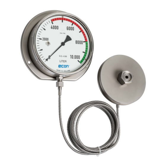
Summary of Contents for ERIKS ECON HCG 8370
- Page 1 ECON HCG 8370 Self-powered Automatic Contents Gauges USER MANUAL YARD HULL NUMBER IMO NUMBER YEAR ERIKS REF. CLASSIFICATION SHIPSNAME TYPE OF SHIP OWNER Rev.1 Page 1 of 16...
-
Page 2: Table Of Contents
CONTENTS SECTION 1 1.1 Introduction 1.2 Description & Operation 1.3 Filling & Emptying the Tank SECTION 2 2.1 Installation 2.2 Installing the transmitter 2.2.1 Installing the transmitter (external type) 2.2.2 Installing the transmitter (internal type) 2.3 Installing the capillary 2.4 Installing the indicator SECTION 3 3.1 Specification SECTION 4... - Page 3 7.1 Ordering information 7.2 Available types and installation: ERIKS bv reserves the right at any time and without notice to make specification changes, in order to improve product design and performance, and as a consequence to revise manual contents where necessary.
-
Page 4: Introduction
SECTION 1 1.1 Introduction: The HCG 8370 Series Hydrostatic tank Contents Gauge, ECON figure 8370, has long been considered as one of the most reliable forms of tank gauging equipment available. The instrument will indicate continuously the liquid contents of any shape of storage tank, and display the data at considerable distance from the tank. -
Page 5: Installation
SECTION 2 2.1 Installation: WARNING: Incorrect use of the gauge system can cause damage and injuries. Under this Directive, the user ensures that the gauge system is installed and used in such way that hazards are eliminated to a maximum extent. Safety instructions: The appropriate national safety regulations must be observed when mounting and operating these gauge systems. -
Page 6: Installing The Transmitter
the indicator in position, so that where is less risk of the instrument being damaged when the capillary in unrolled. With the internal transmitter it may practical to disconnect the capillary tubing from the indicator or the bulkhead fitting. In such a case the disconnected coupling of the capillary should be adequately protected from mechanical damage when routing the capillary. -
Page 7: Installing The Transmitter (Internal Type)
Care must be taken to ensure that the flange has a machined face, and that any weld does not foul the transmitter. The diaphragm detects the hydrostatic head of the tank contents through a full bored hole: THE HOLE MUST BE DRILLED BEFORE FITTING THE TRANSMITTER. The transmitter may be fitted using an isolating valve. -
Page 8: Installing The Indicator
Although the capillary stainless steel covering is of a robust quality, provide a shield where mechanical damage is likely to occur. Capillary bends should not have a radius of less than 5 cm. Avoid routing the capillary where it could be used as a “pipe on which to hang objects”. Do check capillary armoured cover for signs of damage (cuts, weld spatter, burns etc.) particularly inside the tank area. -
Page 9: Maintenance
Tank connection : Depending on type Material flange : AISI316/1.4401 Material diaphragm : AISI316/1.4401 Capillary lengths Maximum length 10 metre. Longer is possible but will slow down the indication. Capillary material : red copper with SS armoured cover Material armoured cover : AISI304/1.4301 Indicators Indicator size... -
Page 10: 1) External Type Transmitter
4.1.2.1) External type transmitter When external type transmitter is employed on an installation viscous fuel, the transmitter should be heavily logged and, if possible, fitted with an electrical tracer. Alternatively, the transmitter should be positioned close to outflow heaters etc. Where water is being measured and the tank is exposed to the weather, normal winter precautions must be observed to prevent the transmitter being damaged by the formation of ice around the diaphragm. -
Page 11: 2) Internal Type Transmitter
4.1.2.2) Internal type transmitter When internal type transmitter is employed on an installation viscous fuel, the transmitter should be heavily logged and, if possible, fitted with an electrical tracer. Alternatively, the transmitter should be positioned close to outflow heaters etc. Where water is being measured and the tank is exposed to the weather, normal winter precautions must be observed to prevent the transmitter being damaged by the formation of ice around the diaphragm. - Page 12 A reset should be made as near as possible to half-scale deflection. Further check readings should be taken at other points on the scale. If the instrument is not within the accuracy guaranteed by ERIKS bv then it should be returned to ERIKS bv for attention.
- Page 13 2. Check that the gauge transmitter is not choked with congealed liquid or sludge. Clean transmitter. 3. Check that the tank’s ventilation is not blocked. If a gauge shows a normal reading when the manhole cover is released, the vent pipe should receive attention. 4 Check that the pointer is not touching the dial or indicator face.
- Page 14 - Use by assembly of capillary new seals, spare seals are tied to the couplings. SECTION 6 6). Transport, packaging and storage 6.1) Transport Check the instrument for any damage that may have been caused by transport. Obvious damage must be reported immediately. Damage through improper transport;...
- Page 15 SECTION 7 7.1 Ordering information: If you want to other new instruments (only supply of complete instruments is possible) please mention the following information on your order: Vessels name IMO number New building number vessel Ships owner Yard vessel built of Serial number of the old instrument, to be find on indicator scale plate above ECON logo Tank name mentioned on scale plate.
- Page 16 7.2 Available types and installation: Rev.1 Page 16 of 16...

Need help?
Do you have a question about the ECON HCG 8370 and is the answer not in the manual?
Questions and answers