
Summary of Contents for Rexnord Thomson Electrak XD
- Page 1 Thomson Electrak ® Electric Linear Actuator Installation Manual Edition 2023-05 www.thomsonlinear.com...
- Page 2 Thomson Version history Edition Reason for revision 2023-05 First edition Warranty The Thomson Electrak XD is warranted to be free from defects in materials and workmanship for a ® period of twelve (12) months from date of delivery. The application of this product is the responsibility of the buyer and Thomson makes no representation or warranty as to the suitability of the product for any particular use or purpose.
-
Page 3: Table Of Contents
Thomson Contents 1. General ...................... 4 1.1 About this manual ....................4 1.2 Target group ......................4 1.3 Symbols used ......................4 1.4 Transport and storage .................... 4 1.5 Packaging ......................4 1.6 Disposal ......................... 4 1.7 Support ........................4 2. -
Page 4: General
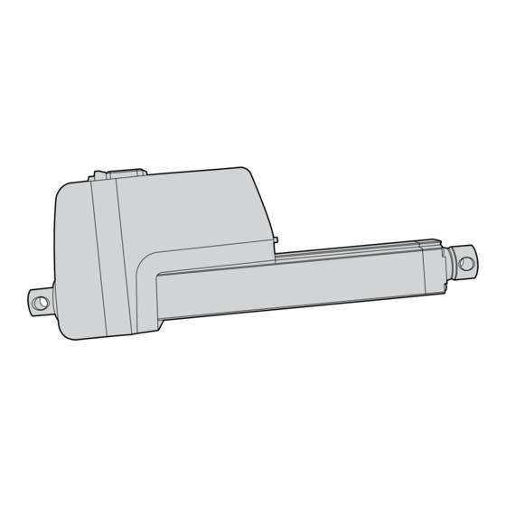
Thomson 1. General 1.1 About this manual This manual contains mechanical and electrical installation instructions for the Thomson Electrak ® electric linear actuator. It also contains, among other things: • technical data • installation data • type designation key. It is important to carefully read this manual before installing the actuator and to have the correct qualifications needed to perform the installation. -
Page 5: Safety
Thomson 2. Safety 2.1 Safety notes • Only properly qualified personnel are permitted to perform mechanical and electrical installation of this product. Properly qualified personnel are familiar with mechanical or electrical installation work and have the appropriate qualifications for their job. •... -
Page 6: Installation
Thomson 4. Installation 4.1 Product label The product label can be found on the side of the cover tube. It will tell you which model of actuator you have, its basic performance data and where it is manufactured. Please study the product label to determine actuator type before starting any installation or service on the actuator. -
Page 7: Operation Environment
Thomson 4.3 Operation environment Min. -40° C (-40° F) Max. +85° C (+185° F) IP67 / IP69K 1. Operation temperature range is -40 to +85° Celsius (-40 to +185° Fahrenheit). 2. Protection degree against the ingress of water and particles is IP67 / IP69K. 3. -
Page 8: Mechanical Installation
Thomson 4.4 Mechanical installation 4.4.1 General installation safety notes • Never work on the actuator with the power switched on. • Do not hold the extension tube while the unit is energized. • Failure modes of the actuator should be considered to ensure it does not create harm. 4.4.2 Basic installation considerations 1. - Page 9 Thomson Dimensions Projection mm [inch] Rear adapters Front adapters Type M Type M Type N Type N Type P Type H Type H Type K Ltot: Total length A: Retracted length S: Ordering stroke A1: Manual override input A2: Manual brake release Type M + dampening option All adapters shown in standard orientation.
- Page 10 Thomson 4.4.4 Mounting orientation and forces The actuator can be mounted in any orientation and handle both pushing and pulling loads. Always install actuator so that the force of the load acts in the center of the extension tube and the rear adapter.
- Page 11 Thomson 4.4.6 General manual brake release and manual override notes - optional features Make sure when mounting the actuator that there is space enough between the front of the motor and any object to allow both the manual brake (a) release and the override (b) controls to be operated. See drawing below for their positions and dimensions.
- Page 12 Thomson 4.4.8 Manual override operation - optional feature The manual override allows the extension tube to be moved at power off by manually cranking it in the desired direction using the manual override input. 1. To operate the manual override, remove the cover plug (a) using a 8 mm hex bit. Then turn on the manual override input hexagon (b) using an 8 mm hex bit (c).
-
Page 13: Electrical Installation
Thomson 4.5 Electrical installation 4.5.1 General notes • Make sure the leads/cables leading to the motor can handle the maximum motor current. • An emergency stop is recommended to reduce the chance of a crushing hazard. • Never work on the actuator or the wiring with the power switched on. 4.5.2 Fuse Use a slow blow fuse on the supply voltage input wiring to protect the actuator and the wiring. - Page 14 Thomson 4.5.5 Power supply requirements The power supply used to power the actuator must fulfill the following requirements. 1. The power supply must be sized so that it can handle both the average power over the duty cycle, as well as the peak current and the inrush current (section 4.5.6). 2.
-
Page 15: Control Options Installation And Operation
Thomson 4.6 Control options installation and operation 4.6.1 General notes • Avoid placing signal cables along power cables to reduce the risk of interference. • Avoid using a vehicle earth as the return conductor. Instead use a two wire system to reduce the risk of interference. - Page 16 Thomson 4.6.4 How to determine the control option Electrak XD is equipped with one of the control options in the table below. To determine the option your actuator has, check the model number on the product label on the actuator (section 4.1) and then check the ordering key (section 8.3).
- Page 17 Thomson 4.6.6 Speed control input (not applicable for units with option CNO/COO) If the speed control input is not used when the extend and retract inputs are active, the actuator will move at its full speed as long as the max. load is not exceeded. If a 0 - 5 Vdc signal is connected to the speed control input, the speed of the actuator can be regulated between 20 - 100% of its full speed where 0 - 0.5 V corresponds to full speed and 1 - 5 V corresponds to 20% of full speed up to full speed.
- Page 18 Thomson 4.6.8 Force feedback function for options CNO/COO In order to use the force feedback function, the actuator must be equipped with an integral force feedback sensor (rear adapter type K). The force is then sent over the bus according to the message structure for the type of bus being used.
- Page 19 Thomson 4.6.12 Control option LXX wiring diagram Fuse Control Option LXX Features Extend switch/relay Retract switch/relay Electrak Monotoring package section 4.6.4 Extend / retract inputs section 4.6.5 Speed control input section 4.6.6 Force feedback function section 4.6.7 speed control input Input Voltage and Current Draw force feedback output...
- Page 20 Thomson 4.6.14 Control option LXP wiring diagram Fuse Control Option LXP Features Extend switch/relay Electrak Monotoring package section 4.6.4 Retract switch/relay Extend / retract inputs section 4.6.5 Speed control input section 4.6.6 Force feedback function section 4.6.7 Position feedback output section 4.6.10 speed control input force feedback...
- Page 21 Thomson 4.6.16 Control option PLS wiring diagram Fuse Control Option PLS Features Extend switch/relay Electrak Monotoring package section 4.6.4 Retract switch/relay Set programmable Extend / retract inputs section 4.6.5 software limits switch Speed control input section 4.6.6 Force feedback function section 4.6.7 Position feedback output section 4.6.10...
- Page 22 Thomson 4.6.17 Control options CNO and COO This document assumes the user is familiar with the SAE J1939 and CANopen standards. Terminology from the standard is used, but not described in detail. See sections 5 and 6 for information on J1939 and CANopen operation and communication protocols, respectively.
- Page 23 Thomson 4.6.17.3 CANopen and SAE J1939 CAN bus installation data Follow wiring guidelines per ISO-11898 Standard CAN 2.0B. Proper termination resistors (120 Ohm) should be placed between the CAN high and CAN low wires in each end of the of the network, see below.
-
Page 24: Sae J1939 Can Bus Information
Thomson 5. SAE J1939 CAN bus information Introduction to SAE J1939 CAN bus This document assumes the reader is familiar with the SAE J1939 standard. Terminology from the standard is used, but not described in detail. The default baud rate is 250kbit/s. The Electrak ® XD actuator is compliant with the standard SAE J1939 and supports the following Parameter Group Numbers (PGNs) from the standard. - Page 25 Thomson 5.2.3 SAE J1939 actuator control message (ACM) All actuator control parameters are adjustable through the proprietary A message (PGN 61184). The preferred transmission repetition rate is 100 ms (can also be sent as required by the application). Additional message specific information can be found in the table below, all other Proprietary A information can be found in the SAE J1939/21 specification.
- Page 26 Thomson 5.2.4 SAE J1939 actuator feedback message (AFM) All actuator feedback data can be retrieved through the proprietary A2 message (PGN 126720). This message is transmitted every 100 ms. Additional message-specific information can be found in the table below, and all other Proprietary A2 information can be found in the SAE J1939/21 specification. A unit with the default address will send out the feedback message with ID 0x19EFFF23.
- Page 27 Thomson Bit 1 – Current/load overload: This flag is used to inform the user that the last motion the actuator attempted caused an overload condition. This occurs when the actuator determines the current set in the Current Limit object from the ACM is exceeded for a consecutive 15 ms. This flag is also set if the set Load Limit is exceeded (section 5.2.3.4).
-
Page 28: Canopen ® Information
Thomson 6. CANopen information ® 6.1 Introduction to CANopen 6.1.1 CANopen standard This document assumes the reader is familiar with the CiA 301 specification released by CAN in Automation. Terminology from the standard is used, but not described in detail. The Electrak® XD actuator is compliant with the standard. - Page 29 Thomson 6.2.2 Control PDO entries The Object Dictionary entries mapped to the RPDO are: Index 0x2100 Name Target Position Object Type Data Type UNSIGNED16 Description The target position for the next actuator motion. The 0.0 mm and full extend stroke values represent 0 to 100% stroke and are only relative to the actual available stroke of the individual unit.
-
Page 30: Actuator Feedback
Thomson 6.2.3 Control PDO example Sending a CAN message with ID 0x223 containing the data 0xE8 0x03 0x64 0x00 0x1E 0x00 0x01 will make an actuator move to position 100 mm, at 30 mm/s, with the current limit set to 10.0 A. The example will work on an actuator with the default Node ID if it is in the operational NMT state. - Page 31 Thomson Index 0x2204 Name Motion Flags Object Type Data Type UNSIGNED8 Index 0x2205 Description Contains information about the current actuator motion. Bit 0 (LSB) – Extending: 1 if currently extending, 0 otherwise. Name Error Flags Bit 1 – Retracting: 1 if currently retracting, 0 otherwise. Object Type Bit2 –...
-
Page 32: Troubleshooting
Thomson 7. Troubleshooting 7.1 Troubleshooting Troubleshooting list Issue Problem Solution Actuator does not move, Actuator is not receiving Ensure the actuator is being supplied with proper rated makes no sound. proper input voltage. input voltage. The actuator, when powered, Fuse is not rated for current Make sure that the fuse is rated for the in-rush current of is causing my fuse to blow. -
Page 33: Technical Specifications
Thomson 8. Technical specifications 8.1 Technical data Technical Specification XD • • Input voltage [VDC] Input voltage tolerance [VDC] 18 - 32 36 - 60 Stroke length [mm] see product label Dynamic load (Fx), maximum see product label Speed, no load / max. rated load [mm/s (in/s)] XD24-B055 65 (2.56) -
Page 34: Duty Cycle
Thomson 8.2 Duty cycle The max. permissible duty cycle is a function of the load and the ambient temperature. The below table is valid for 25°C (77°F). Lower temperatures will increase the duty cycle while higher temperatures will decrease it. Duty Cycle Load [N (lbf)] Load [% of the dynamic load capacity]... -
Page 35: Ordering Key
Thomson 8.3 Ordering key Ordering Key Position XD24 B055- 0200 Example 1. Actuator type and supply voltage 4.Electrak Modular Control System options XD24 = Electrak XD, 24 Vdc LXX = low-level signal motor switching + speed control + force XD48 = Electrak XD, 48 Vdc feedback output LXP = LXX + position feedback output 2. - Page 36 USA, CANADA and MEXICO ASIA Thomson Asia Pacific 203A West Rock Road Thomson E-mail: sales.apac@thomsonlinear.com Radford, VA 24141, USA Phone: +1 540 633 3549 Fax: 1 540 633 0294 China E-mail: thomson@thomsonlinear.com Thomson Literature: literature.thomsonlinear.com Rm 805, Scitech Tower 22 Jianguomen Wai Street Beijing 100004 EUROPE United Kingdom...
Need help?
Do you have a question about the Thomson Electrak XD and is the answer not in the manual?
Questions and answers