Table of Contents
Advertisement
Quick Links
1. GENERAL INFORMATION .................................................................................................................................................................2
1.1. Leveling .......................................................................................................................................................................................2
1.2. Shocks .........................................................................................................................................................................................2
1.3. Electrical soldering ......................................................................................................................................................................2
1.4. Lightning ......................................................................................................................................................................................3
1.5. Outer mechanical influences .......................................................................................................................................................3
1.6. Setting of the counter force .........................................................................................................................................................3
2. CABLING .............................................................................................................................................................................................4
2.1. Cable ...........................................................................................................................................................................................4
2.2. Wiring ..........................................................................................................................................................................................4
2.3. Parallel connection ......................................................................................................................................................................5
2.4. Calibration ...................................................................................................................................................................................5
2.5. Measurement errors ....................................................................................................................................................................5
2.6. Insulation test ..............................................................................................................................................................................6
2.7. Output impedance : .....................................................................................................................................................................6
2.8. Input impedance ..........................................................................................................................................................................7
3. MOUNTING .........................................................................................................................................................................................7
3.1. Mounting with 3 load cells ...........................................................................................................................................................8
3.2. Mounting with more than 3 load cells ..........................................................................................................................................8
4. EU DECLARATION OF CONFORMITY ..............................................................................................................................................9
MA-5910_EN
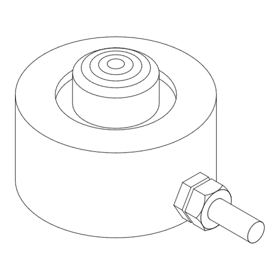
LOAD CELL 5910
INSTALLATION MANUAL
Page 1 on 9
Rev: 26/04/2021
Advertisement
Table of Contents

Summary of Contents for SENSY 5910
-
Page 1: Table Of Contents
LOAD CELL 5910 INSTALLATION MANUAL 1. GENERAL INFORMATION .................................2 1.1. Leveling .......................................2 1.2. Shocks ......................................2 1.3. Electrical soldering ..................................2 1.4. Lightning ......................................3 1.5. Outer mechanical influences ...............................3 1.6. Setting of the counter force .................................3 2. CABLING ......................................4 2.1. Cable ......................................4 2.2. -
Page 2: General Information
Rev. Date Reason 26/04/2021 Insertion of an EU Declaration Of Conformity 1. GENERAL INFORMATION 1.1. Leveling This operation guarantees a good distribution of the loads, as well as the verticality of the effort. It is advised to ensure that a good leveling of the cells and the support elements is carried out. -
Page 3: Lightning
Direct earthing of the structure through the electrical ground strap 1.4. Lightning If there is a risk of lightning, it is advised to isolate the cell the best possible, and to derive the former by stranded wire. To do that, place a rubber sheet under the sole and polyamide waterproof washers under the fixing screws. -
Page 4: Cabling
(preferably screwed connections). It is advised to place a bag of SILICA-GEL to keep dry inside the junction box. SENSY can provide, upon request, a PVC junction box with a PG9 packing-gland – which could receive 4 or 6 parallel cells. -
Page 5: Parallel Connection
If there is no fault to be seen, it is necessary to verify the internal circuit. SENSY can help to diagnose based on the associated diagnosis sheet provided in the appendix and filled in beforehand. -
Page 6: Insulation Test
2.6. Insulation test The measuring of the insulating resistance is done with a multimeter. The standardized testing voltage is 10 V. It is applied to a conductor. It can be determined by disconnecting the measuring instrument and applying voltage between one of the conductors and the metallic mounting structure - or individually, cell by cell, to locate the leakage with precision. -
Page 7: Input Impedance
2.8. Input impedance Input signal (IN+: brown, IN-: yellow): its resistance is usually of ± 700 Ω ± 5 Ω, its impedance must be in accordance with the individual cell data sheet. If a different resistance is read, it means that there is a break-off or a short circuit current. -
Page 8: Mounting With 3 Load Cells
3.1. Mounting with 3 load cells This mounting offers the best load repartition properties and movement space for the element to weigh. 3.2. Mounting with more than 3 load cells When using more than 3 load cells, each element must be placed at the same level, to obtain an optimal distribution of the loads. -
Page 9: Eu Declaration Of Conformity
CONCERNED ITEMS: 5910, see calibration certificate related to model and serial number. SENSY S.A. certify that the items described here above have been duly designed, manufactured and tested for use in accordance with the essential requirements defined in the European Directives listed here under.
Need help?
Do you have a question about the 5910 and is the answer not in the manual?
Questions and answers