
Subscribe to Our Youtube Channel
Summary of Contents for Grunbeck GENO-Neutra FNH-420-R
- Page 1 We understand water. Neutralisation system | GENO-Neutra FNH-420-R Operation manual...
- Page 2 General Contact Germany International Sales +49 9074 41-145 Service +49 9074 41-333 service@gruenbeck.de Availability Monday to Thursday 7:00 am - 6:00 pm Friday 7:00 am - 4:00 pm We reserve the right to technical modifications. © by Grünbeck Wasseraufbereitung GmbH Original operation manual Edition: April 2022 Order no.: 410838-inter _105...
-
Page 3: Table Of Contents
Table of contents Table of contents Introduction ........5 Start-up/commissioning ....55 Validity of the manual ...... 5 Preliminary work ......55 Other applicable documents .... 5 Calibrating the pH electrode ..57 Product identification ....... 6 Checking the product ..... 66 Symbols used ........ - Page 4 Table of contents Dismantling and disposal ... 106 11.1 Dismantling ........106 11.2 Disposal ........107 Technical specifications ..... 109 Operation log ....... 112 13.1 Start-up/commissioning log ..112 4 | 120...
-
Page 5: Introduction
Illustrations in this manual are for basic understanding and can differ from the actual design. 1.1 Validity of the manual This manual applies to the product below: ● Neutralisation system GENO-Neutra FNH-420-R 1.2 Other applicable documents ● Instructions of optional accessories ● Safety data sheet of neutralising agent GENO-Neutrox... -
Page 6: Product Identification
Introduction 1.3 Product identification You can identify your product based on the product designation and the order no. indicated on the type plate. ► Check whether the products indicated in chapter 1.1 corres- pond to your product. The type plate is located on the side of the neutralisation box. Designation Designation Product designation... -
Page 7: Symbols Used
Introduction 1.4 Symbols used Symbol Meaning Danger and risk Important information or requirement Useful information or tip Written documentation required Reference to further documents Work that must be carried out by qualified specialists only Work that must be carried out by qualified electricians only Work that must be carried out by technical service personnel only 1.5 Depiction of warnings This manual contains information and instructions that you must... -
Page 8: Requirements For Personnel
Introduction Warning symbol and Consequences if the information/ signal word instructions are ignored DANGER Death or serious injuries Personal WARNING Possible death or serious injuries injury CAUTION Possible moderate or minor injuries Possible damage to components, the Damage to NOTE product and/or its functions, or an object property in its vicinity... - Page 9 Introduction Personnel Requirements • Extended product-specific expertise Technical service (Grünbeck's technical • Trained by Grünbeck service/authorised service company) 1.6.2 Authorisations of personnel The table below describes which tasks may be carried out by whom. Operator/ Owner/ Qualified Technical user operating specialist service company...
- Page 10 Introduction 1.6.3 Personal protective equipment ► As an owner/operating company, make sure that the requi- red personal protective equipment is available. The components below fall under the heading of personal protective equipment (PPE): Protective gloves Protective footwear Safety goggles Protective overall or (tightly fitting) protective apron 10 | 120...
-
Page 11: Safety
Safety Safety 2.1 Safety measures ● Obey the local regulations on accident prevention and occu- pational safety. ● Obey the following regulations on the treatment and dischar- ge of condensate originating from condensing boilers into the public sewer system: • Work sheet DWA-A 251:2011 "Condensates from con- densing boilers"... - Page 12 Safety ● Only operate your product if all components are installed pro- perly. ● Do not make any changes, alterations or extensions on your product. ● Only use genuine spare parts for maintenance or repair. ● Keep the premises locked against unauthorised access to protect imperilled or untrained persons from residual risks.
- Page 13 Safety ● Obey in-house instructions when handling chemicals. Make sure that protective and emergency equipment such as emergency showers and eyewash are available where requi- red, and functional. Mixing and residual amounts of chemicals ● Do not mix different chemicals. Unforeseeable chemical reac- tions posing a lethal danger can occur.
- Page 14 Safety 2.1.4 Danger due to condensate ● Non-neutralised condensate is acidic and can cause chemical burns and irritation when coming into contact with the skin or the eyes. ● Avoid any skin/eye contact with the condensate. ● Use personal protective equipment when working with con- densate.
-
Page 15: Product-Specific Safety Instructions
German Ordinance on Hazardous Substances. ● Keep the neutralising agent away from children. ● For neutralisation systems GENO-Neutra FNH-420-R, only the manufacturer’s original GENO-Neutrox must be used. ● The neutralising agent is alkaline and can cause chemical burns and irritation when coming into contact with the skin or the eyes. - Page 16 Safety 2.2.2 Safety devices ● Delivery pump featuring a protective temperature limiter with automatic reset. ● The pump motor is switched off in the event of overheating and restarts automatically after it has sufficiently cooled down. ● Level probe to monitor the filling level ●...
- Page 17 Safety 2.2.4 Signals and warning signs Labels on the product Risk of electric shock Risk of chemical burns The affixed information and pictograms must be clearly legible. They must not be removed, soiled or painted over. ► Obey all warnings and safety instructions. ►...
-
Page 18: Conduct In Emergencies
Safety 2.4 Conduct in emergencies WARNING Pressurised media lines ● After the mains plug is unplugged, media lines on the pres- sure side are still under pressure. ● Dosing media splashing out ► Use personal protective equipment. ► Relieve the pressure on the pressure side of the dosing pump before working on the dosing pump, its equipment parts or the dosing lines. -
Page 19: Product Description
DWA A 251:2011 and DVGW VP 114 up to the spe- cified capacity. 3.1.1 Possible applications ● The neutralisation system GENO-Neutra FNH-420-R is de- signed exclusively for use in industrial and commercial appli- cations. ● The condensate can also contain impurities, combustion resi- dues and, in case of oil operation, unburnt hydrocarbons or oil. -
Page 20: Product Components
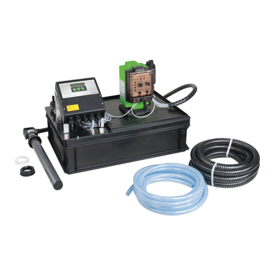
Product description 3.3 Product components Designation Designation Neutralising agent GENO- pH electrode Neutrox (optional, not included Dosing hose in the scope of supply) Suction lance with pre-alarm Dosing pump GENODOS GP and empty signal Suction and return pipe Connection DN 25 (inlet) Control unit GENO-Neutra- matic Connection DN 25 (overflow) - Page 21 Product description Designation Designation Condensate filter for activated Level probe carbon Non-return valve with flat seal Circulation distribution line Hose nipple DN 12 with flat Circulation pump seal Dosing valve Filter cage pH electrode Connections Designation Inlet Overflow Outlet to the drain 21 | 120...
-
Page 22: Functional Description
Product description 3.4 Functional description The condensate flows via the integrated condensate filter into the collection area of the neutralisation box where it is circulated, and the neutralising agent GENO-Neutrox is added. By means of the neutralising agent GENO-Neutrox, the acid con- densate is raised to an admissible pH level so that it can be discharged to the sewer system. - Page 23 Product description features a protective temperature limiter with automatic reset. The pump motor is switched off in the event of overheating and restarts automatically after it has sufficiently cooled down . The integrated filter cage protects the delivery pump from coarse impurities.
-
Page 24: Accessories
Product description 3.5 Accessories You can retrofit your product with accessories. Please contact your local Grünbeck representative or Grünbeck’s headquarters in Hoechstaedt/Germany for details. Illustration Product Order no. Condensate prefiltration box DN 25 410 135 In case of gas/oil switchover operation of a condensing boiler or in case of an otherwise increased dirt content (e.g. - Page 25 Product description Illustration Product Order no. GENODOS suction lance B 10/20, 750 mm 118 505 For 75 kg canisters Voltage-free level signal 163 870 for GENODOS GP For relaying the pre-alarm level of the suction lance 25 | 120...
-
Page 26: Transport, Set-Up And Storage
Transport, set-up and storage Transport, set-up and storage 4.1 Shipping/Delivery/Packaging The product is packed in a cardboard box at the factory. ► Upon receipt, immediately check for completeness and transport damage. ► The activated carbon is not considered to be a hazardous substance in the sense of the German Ordinance on Ha- zardous Substances. -
Page 27: Storage
Transport, set-up and storage ● Transport must be carried out in accordance with ADR. Simplified regulations for transport apply within the framework of the German “Craftsmen’s Regulation” or for “small quanti- ties”. Optimum conditions for transport and storage of the neutralising agent are given at the values below: ●... - Page 28 Transport, set-up and storage 4.3.1 Storage and handling the calibration solution ► Store the calibration solution at room temperature (15 °C – 25 °C) – do not expose it to frost. ► Tightly close the bottle containing the calibration solution after use.
-
Page 29: Installation
Installation The installation of the product must be carried out by a qualified specialist only. Installation example I Designation Designation Neutralising agent Overflow hose GENO-Neutrox Inlet hose Drain connection Heat generator with siphon Neutralisation system GENO-Neutra FNH-420-R 29 | 120... -
Page 30: Requirements For The Installation Site
GENO-Neutrox Condensate prefiltration box Drain connection DN 25 Neutralisation system Inlet hose GENO-Neutra FNH-420-R Heat generator Overflow hose 5.1 Requirements for the installation site Obey the local installation directives, general guidelines and techni- cal specifications. ● Protection from frost, severe heat exposure and direct sun- light ●... - Page 31 Installation ● Horizontal installation surface with sufficient load-bearing capacity to support the operating weight of the product Space required ● There must be a clearance of at least 800 mm in front of the system for operation. ● Above the system, there must be a clearance of at least 600 mm for installation and maintenance work.
- Page 32 Installation Electrical installation ● 2 separate Schuko sockets within a maximum distance of 1.5 m from the product • The power supply must carry continuous current or be connected in parallel to the burner of the condensing boiler 32 | 120...
-
Page 33: Checking The Scope Of Supply
Installation 5.2 Checking the scope of supply Designation Designation (DN 12) Neutralisation system GENO- Neutra FNH-420-R as compact Hose, 5 m in length (DN 25) for system (pre-assembled) inlet and overflow 3 Hose clamps (20–32) Activated carbon filter filling, 3.5 l 1 Hose clamp (12–20) Operation manual 2 Hose connections DN 25 with... -
Page 34: Water Installation
Installation The small parts are located in the neutralisation box. ► Remove the lid and take out the small parts. The components below are pre-assembled at the factory: ● Dosing pump with console on the lid • Connection kit D 2-4 including dosing hose •... - Page 35 Installation 5.3.1 Preparing the neutralisation system Designation Designation pH electrode Plastic nuts PG 13.5 1. Open the lid of the neutralisation box. 2. Remove the transport locks from the neutralisation box. 3. Remove the bag containing the activated carbon as well as the components from the condensate filter.
- Page 36 Installation 5.3.1.2 Installing the inlet and overflow hose connections 1. Remove the condensate filter from the neutralisation box. 2. Install the inlet and overflow connection. a Place the seals on the connecting pieces from the insi- b Insert the angled overflow connection facing upwards. c Firmly tighten the locknuts from the outside.
- Page 37 Installation 5.3.2 Setting up the neutralisation system ● No flue gas from the condensing boiler must escape via the condensate inlet to the neutralisation system. ● If the condensing boiler does not feature a siphon, a siphon must be installed by the client on site. ●...
- Page 38 Installation 5.3.3 Connecting the neutralisation system Use the hoses supplied with the system to connect the neutralisati- on system. 5.3.3.1 Installing the inlet and overflow hose 1. Shorten the inlet and overflow hose to the required length. 2. Connect the inlet hose to the neutralisation system. 3.
- Page 39 Installation Incorporating additional condensing boilers or/and exhaust systems up to the max. capacity of the neutralisation system is possible by using corresponding T pieces. Laying the overflow hose The overflow hose is routed to a nearby floor drain, so that, in the event of a failure, the condensate temporarily can flow off in a con- trolled way until the failure has been remedied.
- Page 40 Installation Only close the overflow connection with the enclosed cap if it is ensured that no more condensate flows into the neutralisation sys- tem after the condensing boiler has been switched of – even from connected exhaust gas pipes. 5.3.3.2 Connecting the outlet hose to the drain connection Comply with the following when connecting the outlet hose to the drain connection: ●...
- Page 41 Installation 1. Shorten the outlet hose to the required length. 2. Fix the outlet hose at the hose nipple by means of the hose clamp. 3. Fix the outlet hose at the drain connection with a distance of at least 20 mm. If a longer hose line is used, the actual delivery rate must be che- cked by “gauging”...
- Page 42 Installation 5.3.4 Connecting the dosing lines and the suction lance 5.3.4.1 Connecting the dosing hose The dosing hose is connected to the dosing valve on the circulation pump at the factory. The dosing hose is pre-assembled at connection kit D 2-4 of the dosing pump.
- Page 43 Installation 1. Connect one hose to the connection nozzle on the suction si- de and fix it with the hose clamp. 2. Connect the second hose to the hose nozzle for the return (la- terally offset at the back) and fix it with the hose clamp. 3.
- Page 44 Installation 5.3.5 Positioning the neutralising agent GENO-Neutrox 1. Position the canister containing the neutralising agent at the designated place. a The canister must be easily accessible. b Take the space required for pulling out the suction lance when replacing the canister into account. 2.
-
Page 45: Electrical Installation
Installation 5.4 Electrical installation The electrical installation must be carried out by a qualified electri- cian only. DANGER Life-threatening voltage on terminal connections ● Severe burns, cardiovascular failure, fatal electric shock ► Only have qualified electricians carry out electrical work on the product. - Page 46 Installation Term. Function Colour Remarks Protective conductor GN/YE Mains cable 230 V~ Neutral conductor Phase Protective conductor GN/YE Delivery pump 230 V~ Neutral conductor Phase Signal contact Boiler off Opens when level a is exceeded for longer than the programmed delay time (max.
- Page 47 Installation Connecting the condensing boiler and the voltage-free contacts to the GENO-Neutra-matic If no floor drain is available, connect a suitable alarm device to terminals 11 and 12 (Brimful) of the GENO-Neutra-matic By connecting the condensing boiler to terminals 7 and 8 of the GENO-Neutra-matic , it must be switched off without delay.
- Page 48 Installation 1. Connect the signal contact Boiler off to terminals 7 and 8 2. Connect the signal contact pH alarm/Service to terminals 9 and 10. 3. Connect the signal contact Brimful to terminals 11 and 12. 4. Connect the contact output for actual pH value to terminals 25 and 26.
- Page 49 Installation 5.4.2 Contact connections Dosing pump GENODOS GP Designation Function • Coupling socket, 3-pole • Level plug in black Input A level probe can be connected to this connection. Empty signal For GENODOS pumps GP-../41, only and exclusively suction lances and empty signals with pre-alarm must be used.
- Page 50 Installation Input connection for empty signal (suction lance) Designation Designation (e.g. float switch) Level probe (200 µs) Level control with pre-alarm Connection cable, 3-pole Designation Colour Ground (reference point) BR (brown) Level empty WH (white) Level pre-alarm GN (green) ● The connector is pre-assembled with the connection cable at the factory.
- Page 51 Installation Input connection for control (GENO-Neutra-matic Designation Designation Analogue control: Hall switch 0–5 V, 1–6 V, 0–20 mA, 4–20 mA Transistor control NPN Ext. operational release (e.g. Relay contact (normally open timer, normally closed contact contact NOC), contacts of water NCC) meter e.g.
- Page 52 Installation Output connection for collective fault signal Components Components Cable socket, 3-pole, with Pg 7 Connection cable, ÖPVC-OZ screw connection 3x0.5 with wire end ferrules 0.50 mm², orange Connections Colour 1 + 3 = Operation BU (blue) 2 + 3 = Fault BR (brown) Changeover contact (common) BK (black)
- Page 53 Installation 5.4.3 Dosing pump GENODOS GP Designation Designation GENO-Neutra-matic Input Empty signal of suction lance Output Collective fault Input Control of 1. Plug the black plug of the suction lance into the connection Input Empty signal Suction lance. a Unscrew the blind plug and remove the existing contact sleeve.
- Page 54 Installation Terminal connections of dosing pump GENODOS GP for voltage-free level signal (optional, order no. 163 870) Designation Designation client on site Connection Empty signal of suction lance Suction lance Pre-alarm Connection Collective fault Empty signal/fault Terminal box provided by the Obey the mounting instructions of the accessory Voltage-free level signal (refer to chapter 3.5).
-
Page 55: Start-Up/Commissioning
Start-up/commissioning Start-up/commissioning The initial start-up/commissioning of the product must be carried out by technical service personnel only. WARNING Acidic condensate/alkaline neutralising agent ● Chemical burns of eyes and body parts ► Use personal protective equipment (refer to chapter 1.6.3). ► Avoid any skin and eye contact with the condensate or the neutralising agent. - Page 56 Start-up/commissioning 6.1.2 Pre-settings of GENODOS pump GP For operation of GENODOS pump GP, refer to chapter 7.2. The installation of the stroke length controller must only be chan- ged during operation and during the pump stroke ● Designation Designation Selector switch for internal and Operating mode switch external control Pulse division or pulse multipli-...
-
Page 57: Calibrating The Ph Electrode
Start-up/commissioning 6.1.3 Establish supply voltage The dosing pump GENODOS GP and the GENO-Neutra-matic switched on and off via the mains plug. ► Plug the two mains plugs of the GENO-Neutra-matic and the dosing pump GENODOS GP into the sockets. 6.2 Calibrating the pH electrode A prerequisite for operating the neutralisation system as intended is that the pH electrode has been calibrated with the pH measuring transducer GENO-Neutra-matic... - Page 58 Start-up/commissioning 1. Connect the pH electrode to the electrode cable of the GE- NO-Neutra-matic 6.2.1 Preparing calibration In order to check and calibrate the pH electrode, you need the utensils below: ● Deionised water in a spray bottle ● Buffer solution pH 7 ●...
- Page 59 Start-up/commissioning ● In order to prevent measuring errors during checking and calibration, the pH electrode must be cleaned and rinsed with deionised water before every check. ● A damaged or slow pH electrode must be replaced. ► Proceed as follows to prepare for the calibration of the pH electrode: Designation Designation...
- Page 60 Start-up/commissioning 6.2.2 Calibrating ► For operation of the GENO-Neutra-matic , refer to chapter 7.1.3. First step (with pH 7) 1. Rinse the pH electrode with deionised water. 2. Dry the pH electrode with a soft cloth. 3. Immerse the electrode into the first buffer solution pH 7. a Wait until the display value for the pH value has stabi- lised.
- Page 61 Start-up/commissioning b Enter the pH value of the second buffer solution at the measuring transducer. » The measuring device determines the zero point and the slope of the electrode. 4. Rinse the pH electrode with deionised water. 5. Dry the pH electrode with a soft cloth. Concluding work As long as no valid calibration has been carried out, the error mes- sage pH Cal is shown in the first line of the GENO-Neutra-matic...
- Page 62 Start-up/commissioning ► After the calibration, re-insert the pH electrode into the ope- ning on the neutralisation box. ► Enter the temperature of the condensate at the measuring transducer. ► Clean the measuring beaker after calibration. NOTE Store buffer solutions properly ●...
- Page 63 Start-up/commissioning 6.2.3 Filling the neutralisation box with water ► Open the lid of the neutralisation box. ► Slowly fill water into the neutralisation box – into the conden- sate filter until the delivery pump delivers the water to the drain. ►...
- Page 64 Start-up/commissioning 6.2.4 Connecting the suction lance to the canister WARNING Skin and eye contact with dosing agent ● Chemical burns to the eyes, irritation of the skin and respira- tory tract when in contact with the dosing agent ► Use personal protective equipment. ►...
- Page 65 Start-up/commissioning 6.2.5 Filling the dosing pump and the dosing line 1. Proceed as follows to set the dosing pump to max. dosing capacity: a Set the frequency selector switch to Int 10 (the dosing pump works at maximum frequency). b Set the stroke length controller to 100 (the dosing pump works at maximum stroke length).
-
Page 66: Checking The Product
Start-up/commissioning 6.3 Checking the product 1. Put the condensing boiler into operation. 2. Check the entire installation for leaks. 3. Check the neutralisation system for function. 4. Make sure that the condensate flows to the drain freely. 5. Check the pump capacity in case of line extensions or reduc- tions in the cross sections of the outlet hose (e.g. - Page 67 Start-up/commissioning The factory settings of the GENO-Neutra-matic and the pre- settings of the dosing pump meet the requirements for “Normal condensate” as specified in the DVGW testing principles. In practice, fault-free operation is achieved with this setting in many cases without the need for making changes. Due to the fluctuating condensate volumes and condensate composition in practice while the condensing boiler is in operation, fluctuations in the pH value within the permissible limit values of pH 6.5 –...
-
Page 68: Handing Over The Product To The Owner/ Operating Company
Start-up/commissioning 6.4 Handing over the product to the owner/ operating company ► Explain to the owner/operating company how the product works. ► Use the manual to brief the owner/operating company and answer any questions. ► Inform the owner/operating company about the need for in- spections and maintenance. -
Page 69: Operation
Operation Operation WARNING Acidic condensate/alkaline neutralising agent ● Chemical burns of eyes and body parts ► Use personal protective equipment (refer to chapter 1.6.3). ► Avoid any skin and eye contact with the condensate or the neutralising agent. ► Thoroughly rinse your eyes with water if condensate or neutralising agent gets into your eyes. - Page 70 Operation Designation Meaning/Function • Info level Display ∙ Basic display to read off the current values • In the basic display: ∙ Switching on the system (press and hold key > 5 sec) • In the Info level: Operating key ∙...
- Page 71 Operation 7.1.1 Basic display By pressing any key, the switched-off display backlighting is swit- ched on again. From any open menu, the display automatically returns to the ba- sic display if no key has been pressed for more than 5 minutes. Previous parameters are retained.
- Page 72 Operation 7.1.2 Reading off the Info level (basic display) In the info level, the current setting values of the parameters below can be read: ● Actual pH value (is continuously shown in the display) ● pH Min. Alarm ● pH Max. Alarm ●...
- Page 73 Operation ► Start the calibration by pressing and holding the key for longer than 2.5 seconds. 1. Enter the measured temperature of the buffer solutions. a Use to enter the temperature. b Confirm with 2. Calibrate with the first buffer solution (pH 7) a Wait until the value displayed does not change any longer.
- Page 74 Operation As long as the difference (measured value for pH 7 – measured value for pH 4) is < 150 mV, Calibration error is displayed. The calibration can only be aborted by using the key combination b Confirm with c Use to enter the pH value of the second buf- fer solution.
- Page 75 Operation 7.1.4 User programming level (Code 113) All parameters that can be changed by the owner/operating com- pany, are stored in the user programming level. ► Reprogram the parameters in Code level 113, if needed. 1. Simultaneously press and hold the keys for more than 1 second.
- Page 76 Operation 7.1.4.1 Parameters Factory settings must only be changed by a qualified specialist and after consultation with Grünbeck’s technical service. In the tables below, the factory settings are greyed out. Parameters Setting range Remarks pH Min. 0.0...5.0...12.0 Lowest pH value to trigger the alarm Alarm pH Max.
- Page 77 Operation Parameters Setting range Remarks The delay time for the output of the signal contact “Boiler off” runs down as long as the highest level a in the neutralisation box is conti- nuously exceeded. Setpoint as target for dosing (controller) Setpoint 0.0...7.5...12.0 •...
- Page 78 Operation 7.1.5 Reading out the error memory (Code 245). In Code level 245, the last 10 errors that have occurred are stored. ► Set Code C 245 via the programming level. » The errors that have occurred are listed as follows: ●...
-
Page 79: Genodos Pump Gp
Operation 7.2 GENODOS pump GP The functions of the operating panel of GENODOS pump GP-../40 and GP-../41 are identical. 7.2.1 Displays and settings Designation Function Pulse division or pulse Setting the pulse division and the pulse multipli- multiplication factors cation Setting different operating modes: 0, T, V and 00, T0, V0 or analogue 0 –... - Page 80 Operation Designation Function Adjustment of the dosing capacity per stroke. The dosing volume is continuously adjustable in the scaling range from 0 – 100. The adjustment Stroke length controller must only be made during operation and during the pump stroke. •...
- Page 81 Operation 7.2.2 Setting the operating mode ► Set the operating mode switch to analogue control 4 – 20 mA 7.2.3 Setting the factors Setting the factors Division T and Multiplication V is not required in case of analogue control via the GENO-Neutra-matic controller.
-
Page 82: Maintenance And Repair
Maintenance and repair Maintenance and repair Maintenance and repair includes cleaning, inspection and mainte- nance of the product. The responsibility for inspection and maintenance is subject to local and national requirements. The owner/operating company is responsible for compliance with the prescribed maintenance and repair work. - Page 83 Maintenance and repair Do not clean the product with cleaning agents con- NOTE taining alcohol/solvents ● Plastic components are damaged. ● Varnished surfaces are affected. ► Use a mild/pH-neutral soap solution. ► Use personal protective equipment. ► Only clean the outside of the product. ►...
-
Page 84: Intervals
Maintenance and repair 8.2 Intervals By way of regular inspections and maintenance, malfunctions can be detected in time and product failures might be prevented. ► As owner/operating company determine which components must be inspected and maintained at which intervals (load- dependent). -
Page 85: Inspection
Maintenance and repair 8.3 Inspection You as owner/operating company can carry out the regular inspec- tions yourself. Initially, we recommend inspecting the product at shorter intervals and later on as required, but at least every 2 mon- ths. ► Carry out an inspection at least every 2 months. Prerequisite During start-up/commissioning, the owner/operating company must have been trained by Grünbeck’s technical service personnel... - Page 86 Maintenance and repair 1. Stop the inflow of condensate or divert it into a suitable collec- tion vessel. 2. Unplug both of the mains plugs. 3. Make sure that the system is de-energised. Performing an inspection 1. Open the lid of the system. 2.
- Page 87 Maintenance and repair a Remove the oil film with an oil binding mat. b Do not use any loose oil binding agents. These might clog the circulation and the delivery pump. Contact the service personnel for condensing boilers if the oil film can be traced back to a boiler malfunction.
-
Page 88: Maintenance
Maintenance and repair 8.4 Maintenance Regular work is required in order to ensure the proper functioning of the product in the long term. Maintenance must be carried out at regular intervals – depending on the amount, contamination and pH value of the condensate as well as on the fuel and boiler type –... - Page 89 Maintenance and repair ► Carry out all activities listed under Inspection. ► Check all electrical connections for damage and a tight fit. ► In addition, carry out cleaning on the components below: 8.4.1.1 Cleaning the circulation pump and the distribution line NOTE Circulation pump running dry ●...
- Page 90 Maintenance and repair Designation Designation Pump grate, grey Motor body Pump lid Ceramic axis Retaining ring Pump impeller 6. Gently squeeze the pump grate at the side and pull it out of the locking device. 7. Open the pump lid by turning it to the left and remove it. 8.
- Page 91 Maintenance and repair 8.4.1.2 Cleaning the delivery pump The delivery pump is maintenance-free when used as intended. Maintenance is limited to cleaning work and functional checks. Any contamination inside the delivery pump can result in a reduc- tion in the delivery rate and in a functional failure of the delivery pump.
- Page 92 Maintenance and repair Designation Designation Seal (O-ring) Impeller Screws Level probe Non-return valve 1. Rinse the delivery pump with clear water to remove loose sludge. 2. Visually check the delivery pump for damage. 3. In the event of malfunctions or obstructions to the free running of the delivery pump, carry out the cleaning work below: a Remove the lid of the impeller.
- Page 93 Maintenance and repair d Properly put on the lid again with the seal in place – pressure chamber above pressure socket. NOTE Lid must be mounted tightly ● Leaks at the lid of the impeller result in a reduction of the de- livery pump’s capacity.
- Page 94 Maintenance and repair 1. Clean all parts of the GENODOS dosing pump that come into contact with chemicals. 2. Replace the suction and pressure valve every year. 3. Check the suction lance and the dosing lines for deposits, in- crustations and damage. 4.
-
Page 95: Consumables
Maintenance and repair 8.5 Consumables The pH electrode and the activated carbon filling are considered to be consumables as their service life directly depends on the system load. Product Quantity Order no. GENO-Neutrox, 25 kg canister (dosing agent) 180 350 GENO-Neutrox, 75 kg canister (dosing agent) 180 355 ecoLine pH electrode... -
Page 96: Wearing Parts
Maintenance and repair 8.8 Wearing parts Wearing parts must be replaced by qualified specialists only. Wearing parts are listed below: ● Seals Designation Designation Delivery pump (centrifugal Filter cage immersion pump SPV 18-170) Condensate filter Non-return valve Circulation pump pH electrode with cable Dosing valve 96 | 120... - Page 97 Maintenance and repair Wearing parts on GENODOS GP Designation Designation Pressure valve Venting membrane Suction valve Valve pin Dosing membrane Seals 97 | 120...
-
Page 98: Troubleshooting
Troubleshooting Troubleshooting 9.1 GENO-Neutra-matic messages By reading out the error memory of the GENO-Neutra-matic possible malfunction can be detected (refer to chapter 0). Display Explanation Remedy ► Check the outlet hose Alarm The highest level a is Brimful reached in the neutrali- ►... -
Page 99: Malfunctions Of Delivery And Circulation Pump
Troubleshooting 9.1.1 Other observations Observation Explanation Remedy ► Replace pH electro- The pH measurement is Frost damage to pH very slow during calibra- electrode (admissible stora- ge temperature -5 °C – tion +30°C) ► Replace electrode pH measurement cannot Moisture has penetrated be calibrated (always pH cable or plug-in cable and use a new... - Page 100 Troubleshooting Observation Explanation Remedy ► Drain and unscrew Delivery pump switches Non-return valve dirty or on repeatedly even damaged, the outlet hose though no condensate is • causing the condensate ► Pull out the non-return flowing in to flow back into the valve using pointed neutralisation box pliers and clean it...
-
Page 101: Malfunctions Of Genodos Gp
Troubleshooting 9.3 Malfunctions of GENODOS GP Designation Designation LED Operation indicator (green) LED Dosing monitoring (red) Glass cartridge fuse 5x20 type LED Empty signal (yellow) MT, medium time lag, 0.125 A LED Membrane monitoring (red) 1. Eliminate the malfunction. 2. Monitor the messages on the control unit. 3. - Page 102 Troubleshooting Display Explanation Remedy agent lights up or ► Check level probe of suction When flashing: flashes lance Pre-alarm undershot ► Replace dosing membrane LED Membrane Dosing membrane de- monitoring (red) fective lights up ► Replace venting membrane Venting membrane defective ►...
- Page 103 Troubleshooting Observation Explanation Remedy ► Detach the hose on Leak at the connection Hose expanded too far kits the connection kit in question and cut off approx. 1 cm ► Re-attach and secure the hose 103 | 120...
-
Page 104: Malfunctions Of Neutralisation System
Troubleshooting 9.4 Malfunctions of neutralisation system Observation Explanation Remedy ► Clean filter tank and Overflowing condensate Activated carbon filling or filter outlet hole at the bottom replace, if needed highly contaminated ► Replace activated carbon filling ► Clean the component Overflowing neutralisati- Filter cage of delivery on box... -
Page 105: Decommissioning
Decommissioning 10 Decommissioning If a longer standstill is planned for the neutralisation system, the neutralisation system must be decommissioned. 10.1 Temporary standstill If the heat generator and the neutralisation system are to be swit- ched off temporarily (e.g. for 3 months in the summer), carry out the activities below: 1. -
Page 106: Dismantling And Disposal
Dismantling and disposal 11 Dismantling and disposal 11.1 Dismantling ► Have this work carried out by qualified specialists only. 1. Make sure that the heat generator is out of operation and no condensate is produced by the neutralisation system. 2. Pull the mains plugs. 3. -
Page 107: Disposal
Dismantling and disposal 11.2 Disposal ► Obey the applicable national regulations. Packaging ► Dispose of the packaging in an environmentally sound man- ner. Danger to the environment due to incorrect dispo- NOTE ● Packaging materials are valuable raw materials that can be reused in many cases. - Page 108 Dismantling and disposal Neutralising agent GENO-Neutrox and canisters The neutralising agent GENO-Neutrox is a base and must not enter the sewage system in concentrated form. ► Obey the safety data sheet of the neutralising agent GENO- Neutrox. ► Rinse the empty canister with a large amount of water. Product If this symbol (crossed-out wheelie bin) is on the product, this pro- duct or its electrical and electronic components must not be dispo-...
-
Page 109: Technical Specifications
Technical specifications 12 Technical specifications Dimensions and weights FNH-420-R Length Total length with connections Total height Height of neutralisation box Width Connection height of inlet and overflow Distance of inlet Height of switch-on level of delivery pump (condensate backwater height in standard operation) Operating weight (with condensate) ~ 35.0... - Page 110 Technical specifications Connection data FNH-420-R Nominal connection diameter of inlet and over- DN 25 flow Nominal connection diameter of outlet hose to DN 12 drain ≥ DN 40 Drain connection provided by the client on site ≥ 41.5 with delivery rate l/min Mains connection, 2 V/Hz...
- Page 111 Technical specifications Characteristic curve of delivery pump Designation Designation Delivery head in m Delivery rate in l/min Note: Pump capacity at a hose length of 6 m (line extensions and reduc- tions in the cross sections of the outlet hose cause a decrease in performance) 111 | 120...
-
Page 112: Operation Log
Operation log 13 Operation log ► Document the initial start-up/commissioning and all mainte- nance activities. Neutralisation system GENO-Neutra FNH-420-R Serial no.: ___________________ 13.1 Start-up/commissioning log Customer Name Address Installation/Accessories Amount of condensate produced Manufacturer of condensing boiler Type of condensing boiler ☐... - Page 113 Operation log Maintenance and repair ☐ No ☐ Yes Aluminium parts in contact with the condensate ☐ Gas ☐ Oil ☐ Oil/Gas Fuel Inspection 2 months 2 months Maintenance 12 months 6 months Remarks Start-up/commissioning Company Service technician Work time certificate (no.) Date/signature 113 | 120...
- Page 114 Operation log Maintenance no.___ Work performed Inspection Maintenance Repair Work on the neutralisation unit ☐ cleaned ☐ replaced Condensate filter ☐ replaced Activated carbon filling of the condensate filter ☐ cleaned ☐ replaced Circulation pump ☐ cleaned ☐ replaced Dosing valve on the circulation pump ☐...
- Page 115 Operation log Maintenance no.___ Work performed Inspection Maintenance Repair Work on the neutralisation unit ☐ cleaned ☐ replaced Condensate filter ☐ replaced Activated carbon filling of the condensate filter ☐ cleaned ☐ replaced Circulation pump ☐ cleaned ☐ replaced Dosing valve on the circulation pump ☐...
- Page 116 Operation log Maintenance no.___ Work performed Inspection Maintenance Repair Work on the neutralisation unit ☐ cleaned ☐ replaced Condensate filter ☐ replaced Activated carbon filling of the condensate filter ☐ cleaned ☐ replaced Circulation pump ☐ cleaned ☐ replaced Dosing valve on the circulation pump ☐...
- Page 117 Operation log Maintenance no.___ Work performed Inspection Maintenance Repair Work on the neutralisation unit ☐ cleaned ☐ replaced Condensate filter ☐ replaced Activated carbon filling of the condensate filter ☐ cleaned ☐ replaced Circulation pump ☐ cleaned ☐ replaced Dosing valve on the circulation pump ☐...
- Page 118 EU guidelines in terms of its design, construction and execution. This certificate becomes void if the system is modified in any way not approved by us. Neutralisation system GENO-Neutra FNH-420-R Serial no.: Refer to type plate The aforementioned system also complies with the following directives and provisions: •...
- Page 119 EU Declaration of Conformity Publisher's information Technical documentation Should you have any questions or suggestions regarding this operation manual, please contact Grünbeck Wasseraufberei- tung GmbH’s Department for Technical Documentation directly. Email: dokumentation@gruenbeck.de...
- Page 120 EU Declaration of Conformity Grünbeck Wasseraufbereitung GmbH Josef-Grünbeck-Str. 1 89420 Hoechstaedt/Germany +49 9074 41-0 +49 9074 41-100 info@gruenbeck.com For more information go to www.gruenbeck.com www.gruenbeck.com...
Need help?
Do you have a question about the GENO-Neutra FNH-420-R and is the answer not in the manual?
Questions and answers