Table of Contents
Advertisement
Quick Links
Advertisement
Table of Contents

Summary of Contents for Control Applications Elnet GR
- Page 1 Elnet Electrical Measurements & Power Quality...
-
Page 2: Table Of Contents
Table of Contents CHAPTER 1 ─ INTRODUCTION........5 About the ElNet Multimeter.........5 How to use this manual ...........6 Safety Information...........8 Warranty ..............9 Your comments are welcome.........11 Disclaimer...............12 CHAPTER 2 — INSTALLATION........13 Contents of packaging ...........14 Mechanical mounting ..........15 Wiring Schematics ..........17 Rear Panel Connections ........18 Manufacturing Data. - Page 3 TOU Setting............37 Change language............38 Time Settings............38 Date Settings............40 Zero Accumulating Values ........41 CHAPTER 5 — FRONT PANEL DISPLAYS....42 Current for 3 Phases..........42 Frequency for 3 Phases..........43 Current in Neutral Line ........44 Voltage for 3 Phases ..........46 Active Power for all 3 Phases (P)......47 Reactive Power for all 3 Phases (Q) .....49 Apparent Power for all 3 Phases (S).....50 Power Factor for each Phase.........51...
- Page 4 5.13 .5 Current THD,TDD,KF.........67 CHAPTER 6 — ALARM REPORT ........68 6.1.1. Alarm setting..........69 6.1.2. Display Alarms Report.........71 CHAPTER 7 — DEMAND REPORTS ......72 CHAPTER 8 — DATA LOGGING ........73 CHAPTER 9 — COMMUNICATION........76 Communication Connections........76 Communication Settings ........76 Address ..............77 Baud Rate ............77 Parity ..............78 Communication Set Up .........78...
-
Page 5: Chapter 1 ─ Introduction
CHAPTER 1 ─ INTRODUCTION 1.1 About the ElNet Multimeter Large consumers of electricity e.g. factories, hotels, hospitals, municipalities, need to know the history of their consumption and the quality of the power supply. Details such as Voltage, Current, Power Factor, Hertz, Neutral Current, Energy Demands and all ElNet Energy &... -
Page 6: How To Use This Manual
Certificate of Compliance (C.O.C). 1.2 How to use this manual We at CONTROL APPLICATIONS Ltd, envisage this manual to be used by three types of people, i.e. the Installation Technician, the Senior Electrical Engineer and the end User. For this reason this manual is divided into chapters for ease of reference by each of these different people. - Page 7 ElNet Energy & Power CHAPTER Using Multimeter, describes in detail front Panel, the functions of the control buttons, and the Lock Utility. CHAPTER 4, Parameter Configuration & Settings explains in detail the minimum parameters settings needed by the Senior ElNet Energy Electrical Engineer to set up and configure the &...
-
Page 8: Safety Information
1.3 Safety Information The purpose of this manual is to help you. Please read the instructions carefully before performing any installation and note any precautions. WARNING • Ensure that all incoming AC power and other power sources turned before ElNet performing any work on the Energy &... -
Page 9: Warranty
CONTROL APPLICATIONS Ltd does not accept liability for any damage that may be caused by natural disasters (such as floods, fire, earthquake, lightening etc.). - Page 10 CONTROL APPLICATIONS Ltd is always at your service to advise the customer on any problem that may be encountered regarding any installation, operation, parameter & configuration...
-
Page 11: Your Comments Are Welcome
1.5 Your comments are welcome CONTROL APPLICATIONS Ltd. sincerely thanks you for ElNet Energy & Power Multimeter . We are choosing our confident that it will provide you with many years of trouble free service and give you all the power and energy information and history that you expected from the instrument when you bought it. -
Page 12: Disclaimer
While it is the intention of CONTROL APPLICATIONS Ltd to supply the customer with accurate and reliable information in this User Manual, CONTROL APPLICATIONS Ltd assumes no responsibility for its use, or for any infringement of rights of the fourth parties which may result from its use. -
Page 13: Chapter 2 - Installation
CHAPTER 2 — INSTALLATION In this Chapter you will find the information and instructions that the Installation Technician needs to mount and connect the ElNet Energy & Power Multimeter WARNING! • During operation, hazardous voltages are present in connecting cables and terminal blocks. -
Page 14: Contents Of Packaging
2.1 Contents of packaging ElNet Energy & Power Multimeter is packed and shipped in a carton approximately 24.5 cm long X 19 cm wide X 12 and cm high. Before opening the package, ensure the area, clean and dry. Without using any sharp instruments, carefully open the carton of ElNet Energy &... -
Page 15: Mechanical Mounting
2.2 Mechanical mounting ElNet Energy & Power Multimeter To Mount the NOTE! ElNet Energy & Power Do not mount the Multimeter too close to any main electrical conductors. Allow sufficient space carry ElNet maintenance to the back of the Energy & Power Multimeter Choose a suitable location, and prepare a rectangular hole according to the dimensions shown in Figure 2.1... - Page 16 ElNet • Energy & Power Slide the Multimeter into the pre-prepared rectangular hole (ensure it is the right way up), then push the two mounting clips provided in the packaging into position. Use mild force to ensure the clips are securely positioned on the ElNet Energy &...
-
Page 17: Wiring Schematics
2.3 Wiring Schematics ElNet Energy & Power Multimeter To wire up the Rear Panel Figure 2.3. Schematic Wiring Diagram... -
Page 18: Rear Panel Connections
2.4 Rear Panel Connections Please re-read section 1.3 for safety instructions. To connect the Rear Panel ElNet All Connections, except those to the CT core of the Energy & Power Multimeter are made via terminal connector plugs (Voltage input, Power Supply, Communication etc.). Max. - Page 19 • Ensure the leads from leg “L” of the Current Transformer on Line 1 pass through the bottom of CT core I1A. • Ensure the other end of the lead emerging from the top of C T core 1A is connected to leg “K” of the Current Transformer on Line 1 WARNING! Never allow an open circuit between the two Current...
- Page 20 ElNet Energy & Connect the rest of the connections to the Power Multimeter by means of terminal connector plugs. The Rear Panel (See Figure 2.4.) has all connections printed and is simple to follow. (See table 2-1 for connections) Figure 2.4. Rear Panel...
- Page 21 Description Remarks Designation Line1 Supplied Voltage Through a 6Amp fuse Line2 Supplied Voltage Through a 6Amp fuse Line3 Supplied Voltage Through a 6Amp fuse Neutral From Current Note the correct direction Transformer on Line1 to insert the lead From Current Note the correct direction Transformer on Line2 to insert the lead...
- Page 22 Description Remarks Designation RS485 — - RS485 Comm. (-) Line RS485 — + RS485 Comm. (+) Line RS232 — TXD RS232 Comm. Transmit RS232 — RXD RS232 Comm. Receive RS232 — COM RS232 Comm. Common RJ45 10 BASE-T line to Via standard Network Communications...
-
Page 23: Manufacturing Data
2.5 Manufacturing Data. Press F1 on the keyboard for 6 seconds. The following screen will appear. Figure 2.5. Elnet Information Number Screen Description Ep. Date Production date of software operating system Ep. Time No. of times the program has been updated Version Program version no. -
Page 24: Chapter 3 - Using The Elnet Multimeter
CHAPTER 3 — USING THE ElNet Multimeter In this chapter you will find descriptions and functions of the front panel and the control buttons and how to use them. 3.1 Front Panel To operate the front panel The Front Panel has a graphic screen and 6 operating buttons. All the readings are shown on a state of the art 160 X 128 resolution graphic screen and are explained in detail in Chapter 5. -
Page 25: Control Buttons
3.2 Control Buttons To operate the Control Buttons on Front Panel ElNet Energy & Power Multimeter has six Control Buttons. With these buttons the User Senior Electrical can achieve all the functions necessary. Engineer The Control Buttons are arranged on a keypad below the display screen and require slight finger pressure to click. -
Page 26: Lock Utility
Buttons operate exactly the same as button F1 Button returns to the previous step or to the Main Menu 3.3 Lock Utility To lock and unlock the Control Buttons The Control Buttons can be locked against any unauthorized or accidental usage. NOTE! Only sub menus can be locked. - Page 27 To Lock press for six (6) seconds. A “Keyboard Locked!” message appears on the screen when any button is pressed. Figure 3.3. Keyboard locked To Unlock simply press for six (6) seconds. A “Keyboard Unlocked!” message appears on the screen and normal functions can resume.
- Page 28 Figure 3.4. Keyboard Unlocked NOTE! ElNet GR In the event of a general power failure, the will return to the screen that was showing before the power failure occurred.
-
Page 29: Chapter 4 - Necessary Elnet Settings
CHAPTER 4 — NECESSARY ElNet SETTINGS In this chapter you will find instructions to set the minimum ElNet Energy & settings that are necessary to allow the Power Multimeter to function properly. WARNING! • The selection, installation and settings of the Current Transformer are the most vital and fundamental actions required to ensure the ElNet... -
Page 30: Settings For Current Transformer
4.1 Settings for Current Transformer To set or change settings for Current Transformer NOTE! The most important setting necessary for the proper ElNet Energy & Power functioning of the Multimeter is the Current Transformer setting. The cross section of the leads to the current Transformer must be compatible to the power of the current transformer. - Page 31 Figure 4.1. Check Password NOTE! The password is 1 3 Move the cursor with the F1, F2, F3, & F4 buttons to number 1. (See Section 3.2 for description of button functions). 4 Click The number 1 will appear in the password field. Figure 4.2.
- Page 32 5 Move the cursor to the # Sign with F1, F2, F3, & F4 buttons, (See Section 3-2 for description of button functions). If the incorrect password is inserted into the Password field, an Error message appears Figure 4.3. Error Message Go back to step 3 and start again.
- Page 33 The Technical Menu screen appears Figure 4.4. Technical Menu 7 Scroll to Current Transformers 8 Click The Current Transformer screen appears Figure 4.5. Current Transformer...
- Page 34 The present setting for the Current Transformer is shown. If it is a new installation, the ratio will show 5 A:5 A 9 Click The Insert Value screen appears Figure 4.6. Insert Value Use Button to move the cursor. Use Button to change the value + or -.
-
Page 35: Electrical Connection Check
Electrical Connection Check NOTE! To avoid any problems arising from incorrect Voltage Connections or accidental reversal of Current Transformer Connections, it is necessary to perform a Phase Order Check before continuing. To perform Electrical connection Check See Section 4.1 for instructions to arrive at the Technical Menu 1 From Technical Menu scroll to Connection check 2 Click The Connection Check screen appears... - Page 36 Voltage and Current Messages Message Voltage Current Voltage “OK” present on Lines. Current present in If “OK” is not present on 3 Lines, Lines and synchronized then its not connected correctly with Voltage Lines. If “OK” is not present on 3 Lines, then its not connected correctly Wired in incorrect...
-
Page 37: Tou Setting
4.3 TOU Setting ElNet Energy & Power Multimeter is capable of working in several TOU Settings. The user can choose the TOU Setting according to the country requested. To set TOU See Section 4.1 for instructions to arrive at the Technical Menu From Technical Menu scroll to TOU Setting Click screen appears... -
Page 38: Change Language
4.4 Change language To change language on the display screen NOTE! The “Change Language Utility” toggles between English and Hebrew and works on the Main screen only. Click for 6 seconds 4.5 Time Settings To set Time See Section 4.1 for instructions to arrive at the Technical Menu From Technical Menu scroll to Set Clock Click... - Page 39 The Set Clock screen appears Figure 4.9. Set Clock to select Hour, Minute, Second. to change time. Click to return to Technical menu Click to return to Main menu.
-
Page 40: Date Settings
4.6 Date Settings To set Date See Sectio 4.1 for instructions to arrive at the Technical Menu From Technical Menu scroll to Set Date Click The Set Date screen appears Figure 4.10. Set Date... -
Page 41: Zero Accumulating Values
to select Day, Month, Year. to change Day, Month, Year. Click to return to Technical menu Click to return to Main menu. 4.7 Zero Accumulating Values To set all accumulating values to Zero 1 Repeat step 1 and 2 from Section 4.1. 2 Move the cursor with the F1, F2, F3, &... -
Page 42: Chapter 5 - Front Panel Displays
CHAPTER 5 — FRONT PANEL DISPLAYS In this chapter you will find instructions on how to obtain the ElNet Energy & Power Multimeter readings that the provides, e.g., Current, Voltage Power, Power Factor, Energy, and Power quality. 5.1 Current for 3 Phases To display Current for all 3 Phases 1 From Main Menu scroll to Current &... -
Page 43: Frequency For 3 Phases
5.2 Frequency for 3 Phases To display Frequency for all 3 Phases 1 Display the current screen as described in section 5.1 2 Click “ TABLE” 3 Click “ FREQ” The Frequency screen appears Figure 5.2. Frequency for all 3 Phases... -
Page 44: Current In Neutral Line
You can reset the Peak values by using the “CLEAR” button Read the Frequency in Line 1, Line 2, Line3 5.3 Current in Neutral Line ElNet Energy & By using the Vector value of L1/2/3 Current Power Multimeter calculates the Current in the Neutral Line To display Current in the Neutral Line NOTE! If the reading for neutral line is “0”... - Page 45 Current in Neutral line Figure 5.3. Combined Displays Parameter Description Units Voltage from Line1 to Neutral Volts Voltage from Line2 to Neutral Volts Voltage from Line3 to Neutral Volts Voltage across Line1 and Line2 Volts Voltage across Line2 and Line3 Volts Voltage across Line1 and Line3 Volts Table 5-1 Voltage Readings...
-
Page 46: Voltage For 3 Phases
5.4 Voltage for 3 Phases To display Voltage for all 3 Phases and across Phases 1 From the Main Menu scroll to Current & Voltage 2 Click The Current & Voltage screen appears Figure 5.4. Combined Displays 3 Click “VOLT” The Voltage screen appears... -
Page 47: Active Power For All 3 Phases (P)
5.5 Active Power for all 3 Phases (P) To display Active Power for all 3 phases 1 From Main Menu scroll to Power Display 2 Click The Active Power screen appears Figure 5.5. Active power 3 Click To display Power Table Parameter Description Unit... - Page 48 NOTE! Peak is the highest value reached for the adjacent ElNet Energy & Power reading since the Multimeter was first switched on, Since the last time the reset button was pressed. Peak is the lowest value reached for the adjacent ElNet Energy &...
-
Page 49: Reactive Power For All 3 Phases (Q)
5.6 Reactive Power for all 3 Phases (Q) To display Reactive Power for all 3 phases 1 From Main Menu scroll to Power Display 2 Click The Power Table screen appears Figure 5.6. Active Power To display Reactive Power for all 3 phases in a single screen 3 Click The Reactive Power screen appears Refer to section 5.4 for... -
Page 50: Apparent Power For All 3 Phases (S)
5.7 Apparent Power for all 3 Phases (S) To display Apparent Power for all 3 phases 1 From Main Menu scroll to Power Display 2 Click The Power Table screen appears Figure 5.8. Power Table To display Apparent Power for all 3 phases in a single screen 3 Click Refer to section 5.4 for description of peaks. -
Page 51: Power Factor For Each Phase
5.8 Power Factor for each Phase To display Power Factor for each phase 1 From Main Menu scroll to Power Display 2 Click 3 Click to display “TABLE” format The Power Table screen appears Figure 5.10. Power Table... -
Page 52: Overall Power Factor
4 Click The Power Factor for each Line screen appears Figure 5.11. Power Factor for each line 5.9 Overall Power Factor To display Overall Power Factor 1 From Main Menu scroll to Power Display 2 Click and then click... -
Page 53: Active Energy
The Power Table screen appears Overall Power Factor Figure 5.12. Power Table 5.10 Active Energy To display Overall Active Energy 1 From Main Menu scroll to Energy Display 2 Click The Energy Meter screen appears Active Energy Figure 5.13. Energy Meter... -
Page 54: Reactive Energy
3 Read the Active Energy for Line1, Line2, Line3 To return to Main Menu To return to Main Menu click 5.11 Reactive Energy To display Overall Reactive Energy 1 From Main Menu scroll to Energy Display Click The Energy Meter screen appears Reactive Energy Figure 5.14. -
Page 55: Apparent Energy
5.12 Apparent Energy To display Overall Apparent Energy 1 From Main Menu scroll to Energy Display 2 Click The Energy Meter screen appears Apparent Energy Figure 5.15. Energy Meter 3 Read the Apparent Energy for Line1, Line2, Line3 To return to Main Menu 4 To return to Main Menu Click... -
Page 56: Power Quality
5.13 Power Quality NOTE! Poor Harmonics could invoke a fine and damage to the electrical system and can be improved by adding filters. ElNet Energy & Power Multimeter GRAPHIC Model is capable of displaying Harmonics in Wave Form Graph, Harmonics Bar Graph, Harmonic Tables and Total Harmonic Distortion for Voltage and Current. - Page 57 3. Scroll to Wave Form Graphs 4. Click The Wave Form Graphs screens appear. NOTE! Available Wave Form Graphs Line 1, Line 2 and Line 3 Volts Line 1, Line 2 and Line 3 Current Line 1, Line 2 and Line 3 Active Power Line 1, Line 2 and Line 3 Reactive Power...
- Page 58 2. Press to change Voltage Graph to Line 1, Line 2 and Line 3 To display Current Wave Form Graphs 1. Click The Current Graph screens appears Figure 5.18.Current Graph 2. Press to change Current Graph to Line 1, Line 2 and Line 3...
- Page 59 To display Active Power Wave Form Graphs 1. Click The Active Power Graph screens appears Figure 5.19. Active Power Graph 2. Press to change Active Power Graph to Line 1, Line 2 and Line 3...
- Page 60 To display Reactive Power Wave Form Graphs 1. Click The Reactive Power Graph screens appears Figure 5.20. Reactive Power Graph 2. Press to change Reactive Power Graph to Line 1, Line 2 and Line 3...
-
Page 61: Harmonics Bar Graphs
To display Apparent Power Wave Form Graphs 1. Click The Apparent Power Graph screens appears Figure 5.21. Apparent Power Graph 2. Press to change Apparent Power Graph to Line 1, Line 2 and Line 3 5.13 .2 Harmonics Bar Graphs To display Harmonics Bar Graphs 1. - Page 62 The Power Quality screens appears Figure 5.22. Power Quality 3. Scroll to Harmonic (Graphs) Click The Harmonics Volt Bar Graph screens appears Figure 5.23. Harmonics Bar Graph...
- Page 63 5. Press to change Harmonics Volts Bar Graph to Line 1, Line 2 and Line 3 NOTE! Harmonics is normally 100%. If shown together with the other Harmonics, distortion to the rest of the Harmonic Bar Graph will occur. By toggling ElNet Energy &...
-
Page 64: Voltage Total Harmonic Distortion (Thd)
5.13 .3 Voltage Total Harmonic Distortion (THD) NOTE! ElNet Energy & Power Multimeter is capable of measuring Voltage and Current Harmonic Distortion for the first 60 Harmonics. These are presented in a table format with the Total Harmonics Distortion (THD) also shown. To display Harmonics Tables 1. -
Page 65: Current Total Harmonic Distortion (Thd)
The Harmonics Volt Table screens appears Figure 5.25. Harmonic Volt Table 5. Click to scroll down the Table to observe all Volt Harmonics till 60 6. Click change Harmonics Volt Table to Line 1, Line 2 and Line 3 5.13 .4 Current Total Harmonic Distortion (THD) To display Harmonics Current Table Repeat steps 1-4 from Section 5.13.3... - Page 66 1. Click The Harmonic Current Table screens appears Figure 5.26. Harmonic Current Table 2. Click to scroll down the Table to observe all the Current Harmonics till 60 3. Click change Harmonics Current Table to Line 1, Line 2 and Line 3...
-
Page 67: Current Thd,Tdd,Kf
5.13 .5 Current THD,TDD,KF From Main Menu scroll to Power Quality Display and then scroll to THD, TDD, KF Current. The Current, THD, TDD, KF Table screens appears Figure 5.27. Current THD, TDD, KF In order to enable the system to calculate properly the TDD value, user should set the max line current value by using “F4”. -
Page 68: Chapter 6 - Alarm Report
CHAPTER 6 — ALARM REPORT ElNet Every second automatically the monitor all the electrical values and compare them to the pre-setting alarm values. ElNet can handle and store up to1,000 alarms that are stored in the ElNet memory with their time & date data. ElNet has three alarm relays each one of them can be linked to one or more pre-defined alarms. -
Page 69: Alarm Setting
For each one of the above alarms the user can define two alarms - low value alarm and high value alarm. The user can select one of sixteen different timers in order to delay each one of the alarms. 6.1.1. Alarm setting Technical Menu from the main See chapter No. - Page 70 Set Delay Timers: ElNet Up to sixteen delay timers can be defined in the Multimeter, user can link for each one of the timer one or more alarms, the delay timer will check that the alarm is stable and will not write the alarm in the memory ElNet “ON”...
-
Page 71: Display Alarms Report
6.1.2. Display Alarms Report Two alarm reports can be generated: Historical alarm report – includes all the information about fixed alarms (return to normal status). Current alarm report - includes all the information about existing alarms. In order to generate an alarm report, from the Main Menu scroll to “Alarm report “... -
Page 72: Chapter 7 - Demand Reports
CHAPTER 7 — DEMAND REPORTS ElNet Multimeter can generate reports that will inform the user the date of the maximum demand. The reports include: Maximum Demand – for active power and power factor. Maximum Demand –for reactive power and power factor. Maximum Demand –... -
Page 73: Chapter 8 - Data Logging
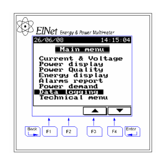
CHAPTER 8 — DATA LOGGING ElNet multimeter collects automatically important electrical data day by day, for approximately two years. From the Main Menu scroll to “Data Logging “ and press Enter. The following screen appears Figure 8.1. Data Logging Daily peaks : Select Daily peaks and press Enter, then you will be able to get the following information: Figure 8.2. - Page 74 For each one of the above options you will have the ability to get for each phase the lowest-level value and the highest-level value as specified in the following screen: Figure 8.3. Current Peaks Select one of the above options and press Enter, the following screen will appear: Figure 8.4.
- Page 75 Power Demand : The operation metod is very similar to the above paragraph “Daily peaks” and the informatin includes the maximum average for 15 minutes of the active power, reactive power and apparent power demand. Total Energy : The operation metod is very similar to the above paragraph “Daily peaks” and the informatin includes the toatl energy values for active energy, reactive energy and apparent energy for each phase and total energy.
-
Page 76: Chapter 9 - Communication
CHAPTER 9 — COMMUNICATION Communication Connections ElNet Energy & Power Multimeter supports RS232 and RS485. Connections for both are provided on the Rear Panel, (see Figure 6.1) and are made by means of the connectors provided. The same information can be transmitted along both, but only one at a time. -
Page 77: Address
Address Each Power meter in a communication system must have its own unique address. ElNet Energy & Power Multimeter works on Since the MODBUS, the available addresses are from ‘1’ to ‘247’. Baud Rate The Baud Rate is the communication speed in Bits per second ElNet Energy &... -
Page 78: Parity
Parity The choices of parity are either NONE or EVEN (see section 6.1.1 for description of Parity). Communication Set Up To set up Serial Communications See Section 4.1 for instructions to arrive at the Technical Menu. From Technical Menu scroll to Communication Settings 1 Click The Communication Setup screen appears Figure 9.2. - Page 79 From Communication Setup Menu scroll to Serial Comm. 2 Click The Communications Settings screen appears Figure 9.3. Communications Settings Use Button to select Address, Baud Rate, Parity Use Button to change value in selected field...
- Page 80 NOTE! When the selection is made it takes immediate affect with no further action required. Click to return to Technical menu. Click to return to Main menu. To set up Ethernet Communications From the Communication Setup Menu scroll to Ethernet Comm. 1 Click...
- Page 81 The Set IP Address screen appears Figure 9.4. Set IP Address Use Button to move the cursor Use Button to change IP Address...
-
Page 82: Communication With Uniart Software
Communication with UniArt Software CONTROL APPLICATIONS Ltd propriety software, “UniArt” is ElNet Energy & used to Read and Write Registers of the Power Multimeter Each Item number in the Registers Table is a unique field containing information. The UniArt software manages each Item number as a parameter. - Page 83 E.G. 1 If the user the wishes to read Voltage Line 2 (Item No 2) By applying the formula: 2 - [0 X 128] = 2 File = 0 and Point within that file = 2 E.G. 2 If the user the wishes to read 30 Harmonics for Volts Line1 (Item No 330) By applying the formula: 330 - [2 X 128] = 74...
-
Page 84: Chapter 10 - Specifications
CHAPTER 10 — Specifications Item Description Power requirements 110/230VAC,60/50 Hz, 30VA Dimensions (HxWxD) 144x144x100 mm Shipping Weight 750 gr. Measuring voltage limits 700 VAC Measuring current limits Operating Voltage limits 1000VAC Operating Current limits Enclosure material ABS Anti flame Display Graphic 160x128 Operating temperature -20 - + 50 C... -
Page 85: Appendix A - Installation & Configuration Check List
Appendix A — Installation & Configuration Check List INSTALLATION CHECK LIST Description Date Signature Check contents of packaging Remove from packaging Prepare hole Mount Multimeter Connect Multimeter power supply Connect 3 Current Transformers Connect 3 Voltage lines Connect Neutral line Set Current Transformer Ratio Connect Communication lines Check Phase Order Connections...
Need help?
Do you have a question about the Elnet GR and is the answer not in the manual?
Questions and answers