Table of Contents
Advertisement
Quick Links
SUN SHIELD HUMIDITY
SERIES
Installation & Operation Instructions
GENERAL INFORMATION
The Solar Radiation Shield is a solution for
protecting temperature and relative humidity
sensors from error-producing solar radiation and
precipitation. The highly reflective white wedge-
shaped plates provide maximum airflow around
the sensors while at the same time minimizing
direct exposure to sunlight. The passive shield is
shaped to allow natural air convection around the
sensors so that the air temperature and relative
humidity inside the shield is a good representation
of the outside air. The RH Sun Shield transmitter
is field selectable with a 4-20 mA, 0-5 VDC, or
0-10 VDC output signal that is equivalent to 0
to 100% RH. This sensor is designed for use with
electronic controllers in commercial heating and
cooling building management systems. All units
are shipped from the factory set up for a 4-20
mA output. The transmitter can also include an
optional temperature sensor for monitoring the
space temperature.
For optimal readings, follow these tips:
• Place the shield in an open area to insure
unrestricted air flow or wind
• Keep away from large radiant heat sources, such
as sun exposed buildings and solar panels.
• Avoid
building
exhaust
machinery, and motors.
• Do not install over or near sprinklers. Continuous
moisture may damage the sensors.
MOUNTING INSTRUCTIONS
The Solar Radiation Shield is designed for two
different mounting configurations such as a metal
pipe with outside diameter between 1" and 1.5"
(U-Bolts included) or on the side of a building or
wooden post (Hardware Not included).
Pole Mounting
• Locate the four U-Bolt mounting holes on the
back panel of the mounting bracket. Attach the
U-Bolts, U-Bolt Washers and 5/16" Hex Nuts as
shown in Figure 2.
Automation Components, Inc.
2305 Pleasant View Road | Middleton, WI 53562
Phone: 1-888-967-5224 | Website: workaci.com
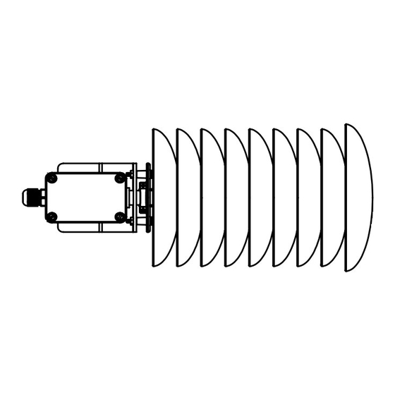
FIGURE 1: ENCLOSURE DIMENSIONS
[64.8mm]
2.55in
[56.7mm]
2.23in
FIGURE 2: MOUNT BRACKET
vents,
electrical
Page 1
Phone: 1-888-967-5224
Website: workaci.com
[379.7mm]
14.95in
[94.0mm]
3.70in
Version: 6.0
I0000647
Advertisement
Table of Contents

Summary of Contents for aci SUN SHIELD HUMIDITY Series
- Page 1 SUN SHIELD HUMIDITY SERIES Phone: 1-888-967-5224 Website: workaci.com Installation & Operation Instructions GENERAL INFORMATION FIGURE 1: ENCLOSURE DIMENSIONS The Solar Radiation Shield is a solution for protecting temperature and relative humidity sensors from error-producing solar radiation and precipitation. The highly reflective white wedge- [64.8mm] shaped plates provide maximum airflow around 2.55in...
- Page 2 Refer to FIGURE 4 (p. 3) or wiring diagrams. TEMPERATURE WIRING INSTRUCTIONS ACI recommends 16 to 26 AWG twisted pair wires or shielded cable for all temperature sensors. ACI recommends a separate cable be pulled for Temperature signal only. Temperature Signal wiring must be run separate from low and high voltage wires (24/120/230VAC).
- Page 3 FIGURE 4: OUTPUT SIGNALS FIGURE 5: PRINTED CIRCUIT BOARD PUSH TAB IN AND PULL UP ON THE SENSOR CABLE TO REMOVE FROM J13 CONNECTOR FACTORY USE ONLY FIGURE 6: TEMPERATURE WIRING Page 3 Automation Components, Inc. Version: 6.0 2305 Pleasant View Road | Middleton, WI 53562 I0000647 Phone: 1-888-967-5224 | Website: workaci.com...
- Page 4 WIRING INSTRUCTIONS HUMIDITY REVERSE ACTING OUTPUT (Continued) The output is direct acting and can be changed to The number of wires needed depends on the reverse acting mode. The output range stays the application. Connect thermistor/RTD wire leads same but the corresponding RH value is opposite. to controller analog input wires using wire nuts, terminal blocks, or crimp style connectors.
- Page 5 RH CALIBRATION (Continued) This can be used to show the user how far offset the transmitter is. To see the starting point again set switch 1 ON. This will show the 50% output again. When the unit is out of setup mode the output will go back to RH output.
- Page 6 PRODUCT SPECIFICATIONS Page 6 Automation Components, Inc. Version: 6.0 2305 Pleasant View Road | Middleton, WI 53562 I0000647 Phone: 1-888-967-5224 | Website: workaci.com...
- Page 7 TROUBLESHOOTING WARRANTY The ACI Outside Series RH sensors are covered by ACI’s Five (5) Year Limited Warranty, which is located in the front of ACI’S SENSORS & TRANSMITTERS CATALOG or can be found on ACI’s website: www.workaci.com. W.E.E.E. DIRECTIVE At the end of their useful life the packaging and product should be disposed of via a suitable recycling centre.
- Page 8 Automation Components, Inc. 2305 Pleasant View Road Middleton, WI 53562 Phone: 1-888-967-5224 Website: workaci.com Page 8 Automation Components, Inc. Version: 6.0 2305 Pleasant View Road | Middleton, WI 53562 I0000647 Phone: 1-888-967-5224 | Website: workaci.com...
Need help?
Do you have a question about the SUN SHIELD HUMIDITY Series and is the answer not in the manual?
Questions and answers