Table of Contents
Advertisement
Quick Links
Advertisement
Table of Contents

Subscribe to Our Youtube Channel
Summary of Contents for Rato RT50ZB26-3.6Q
- Page 1 RT50ZB26-3.6Q/ RT80ZB26-3.6Q/ RT100ZB26-5.2Q WATER PUMP SERVICE MANUAL...
- Page 2 NOTICE: Copyright reserved, and no part of this publication may be reproduced without RATO Company’s written permission. SAFETY MESSAGES Your safety and the safety of others are very important. We have provided important safety messages in this manual and on the generator.
-
Page 3: Table Of Contents
CONTENT PREFACE ............................... 1 1-1 Component identification ......................1 1-2 Specifications ........................... 2 DIMENSION AND TORQUE ....................... 4 2-1 Engine dimension ........................4 2-2 Water pump dimension ......................7 2-3 Torque value ........................... 10 3. MAINTENANCE ............................. 12 3-1 Maintenance schedule ......................12 3-2 Engine oil .......................... -
Page 4: Preface
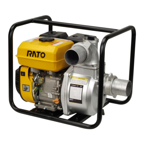
1. PREFACE 1. PREFACE 1-1 Component identification FUEL TANK CAP DISCHARGE PORT CHOKE LEVER FUEL COCK RECOIL STARTER GRIP OIL DIPSTICK ENGINE SWITCH FRAME PRIMING WATER FILTER CAP AIR CLEANER MUFFERLER SUCTION PORT OIL DRAIN PLUG PUMP DRAIN PLUG... -
Page 5: Specifications
1. PREFACE 1-2 Specifications Engine specification Model R200 R270 Items L×W×H 390×320×345mm 355×430×410mm Dry Weight 16Kg 26 kg Engine Type 4-stroke, OHV, single cylinder Displacement 196cm3 270cm3 Compression Ratio 8.5 :1 8.2 :1 Bore×Stroke 68×54mm 77×58mm 4.0kW /3,600rpm 5.8kW/3,600rpm Maximum output Power Maximum Torque 11N·m /2,500rpm 17N·m /2,500rpm... - Page 6 1. PREFACE Water pump specification Model Items RT50ZB26-3.6Q RT80ZB26-3.6Q RT100ZB26-5.2Q Length (mm) Width (mm) Height (mm) Dry weight (kg) 26.5 Suction port diameter 50 mm (2 in) 80 mm (3 in) 100 mm (4 in) Discharge port diameter 50 mm (2 in)
-
Page 7: Dimension And Torque
2.DIMENSION AND TORQUE 2. DIMENSION AND TORQUE 2-1 Engine dimension R200... - Page 8 2.DIMENSION AND TORQUE R270...
- Page 9 2.DIMENSION AND TORQUE PTO dimension figure: Item Figure 13301- Z040310 13301- Z080310...
-
Page 10: Water Pump Dimension
2.DIMENSION AND TORQUE 2-2 Water pump dimension RT50ZB26-3.6Q... - Page 11 2.DIMENSION AND TORQUE RT80ZB26-3.6Q...
- Page 12 2.DIMENSION AND TORQUE RT100ZB26-5.2Q...
-
Page 13: Torque Value
2.DIMENSION AND TORQUE 2-3 Torque value R200 torque value Torque valve Items Specifications N·m kg·m Connection-rod bolt M7 × 1.0 Cylinder head bolt M8 × 1.25 Flywheel nut 70-80 M14 × 1.5(special) Lock nut of rocker arm shaft M8 × 1.25 Rocker arm stud M10 ×... - Page 14 2.DIMENSION AND TORQUE RT50ZB26-3.6Q pump torque specification Torque valve Items Specifications N·m kg·m Frame M8 × 1.25 24±2 2.4±2 Pump body M8 × 1.25 24±2 2.4±2 Connecting tray M8 × 1.25 20±2 2.0±2 Impeller M8 × 1.25 20±2 2.0±2 Suction port M8 ×...
-
Page 15: Maintenance
3. MAINTENANCE 3. MAINTENANCE 3-1 Maintenance schedule Check time Every year or First month or Every 6 months Every 3 months 20 Hrs. Each use or 100 Hrs. 300 Hrs. or 50 Hrs. (3) Check item ○ Oil Check ○ ○ Oil Replace Air cleaner element ○... -
Page 16: Air Cleaner
3. MAINTENANCE R270 torque:24—26N.m OIL DRAIN PLUG 3)Fill the clean oil from the filling port. R200 Oil capacity 0.6L R270 Oil capacity 1.1L General oil: SAE15W-40 SJ class or equivalent API classified SJ class’s SAE10W-30 oil. ※In low temperature(temperature is 10℃ lower),use(SAE10W-30)>。 Recommended oil ※In cold,(temperature is -15℃... -
Page 17: Fuel Oil Cup Cleaning
3. MAINTENANCE 3)Clean the polyurethane element with cleaning oil, then blow with compressed air or squeeze. Dip the element in clean oil, then, forcefully squeeze and install it back. 3-4 Fuel oil cup cleaning Caution · Don’t smoke in washing. ·... -
Page 18: Governor
3. MAINTENANCE CAUTION : Be careful not to oil leaking when dismounting cylinder head cover. 2)Set the piston at top dead center of the compression. 3)Insert a feeler gauge between the rocker arm and valve to measure valve clearance. IN:0.15 ± 0.02 mm Valve clearance EX:0.20 ±... -
Page 19: Disassembling And Servicing
4. DISASSEMBLING AND SERVICING 4. DISASSEMBLING AND SERVICING 4-1 Troubleshooting 4-1-1 Starting Difficult TROUBLE CAUSE REMEDY There is no enough fuel in fuel Fill fuel, open fuel cock. tank and fuel cock is closed. Dredge air vent. Air vent in the fuel filler cap is Fuel supply clogged is not... - Page 20 4. DISASSEMBLING AND SERVICING TROUBLE CAUSE REMEDY Piston ring is worn to or even Replace over its wear limit Piston ring is broken. Replace Piston ring is sticking. Clear up carbon fouling. Abnormal Normal Spark plug is not installed tighten Tighten with a gasket in.
- Page 21 4. DISASSEMBLING AND SERVICING 3. Motor running Motor, relay failure, wiring loosen off and Check and remove the starting electric abnormal starting switch failure. appliance or replace damaged parts.
-
Page 22: Power Lack
4. DISASSEMBLING AND SERVICING 4-1-2 Power lack TROUBLE CAUSE REMEDY Air in fuel line or fuel line clogged Exhaust air or dredge fuel line Main oil flow hole is not adjusted Readjust properly In carburetor, needle valve hole and Clean and blow to get through Ignition system main oil flow hole clogged. -
Page 23: Speed Unstable
4. DISASSEMBLING AND SERVICING 4-1-3 Speed unstable TROUBLE CAUSE REMEDY Piston, cylinder or piston ring is worn excessively. Replace the worn Piston pin and piston pin hole are worn Replace piston or piston pin excessively. Knocking sound Tie rod small head is worn excessively. Replace tie rod Roller bearing for crankshaft main shaft is worn. -
Page 24: Exhaust Gas Color Abnormal
4. DISASSEMBLING AND SERVICING 4. Check the engine Engine power insufficient Refer to “4-1-2 Power lack” 4-1-5 Exhaust gas color abnormal TROUBLE CAUSE REMEDY Piston, cylinder or piston ring is worn excessively. Replace the worn Too much carbon deposit in combustion chamber Clear away Black smoke Too much carbon deposit in combustion chamber... -
Page 25: Oil Alert System Malfunction
4. DISASSEMBLING AND SERVICING 4-1-7 Oil alert system malfunction Check the oil alert system as following method: 1) Disconnect yellow lead of the engine and connect the engine to ground when the engine is running. Be sure alert lamp light up, the engine stop. 2) Disconnect oil level switch lead under the specified condition while the stop and check the continuity of the yellow and green leads, uncontinuity between yellow and green lead is normal. -
Page 26: Preparation Of Servicing
4. DISASSEMBLING AND SERVICING 4-2 Preparation of servicing 4-2-1 Safety precautions WARNING: Indicate a possibility of invalid warranty and personal or equipment damage if instructions are not followed. Please pay special attention to the following: 1. Strictly set the engine according to the regulated power on the nameplate. Do not overload, overrun the engine or run it with low load and at low speed in a long time. - Page 27 4. DISASSEMBLING AND SERVICING 13. Please carefully read warning label before operating. Our company will not assume any responsibility, for person hurt, or equipment damaged caused by disregarding this warning label. (Label is shown as following:) 1.Fuel label(88002-V010210) 2. Reading Owner’s Manual label(88007-V010110) 3.
- Page 28 4. DISASSEMBLING AND SERVICING 5. Warning label(88006-V010710) 6. Warning label(88006-V010810) 7. Warning label(88006-V010610) 8. Crankshaft direction indicator label(88036-V010110) 9. Throttle valve label(88028-Z010110)...
- Page 29 4. DISASSEMBLING AND SERVICING 10. Air cleaner maintenance label(88005-Z010110) 11. Impeller direction indicator label(88035-V010110) 12. Oil brand label(88031-Z010110) 13. Filling oil label(88027-V010110)...
- Page 30 4. DISASSEMBLING AND SERVICING 14. Specification label(88016-V010210/88016-V020210/88016-V030210)...
- Page 31 4. DISASSEMBLING AND SERVICING Special tools 4-2-2 Tool name Application note 1. Float lever gauge Carburetor float level inspection. 2. Valve guide driver Valve guide removal, installation. 3. Retainer assembler Assembling ball bearing. 4. Assembler handle Installing handle and bearing. 5.
-
Page 32: Dismounting Chart
4. DISASSEMBLING AND SERVICING 4-3 Dismounting chart Suction port Discharge port Pump body Impeller Shock absorption Frame Connecting tray Muffler Gasoline engine Fuel tank Carburetor Flywheel Igniter coil Air cleaner Shroud Recoil starter... -
Page 33: Gasoline Engine
4. DISASSEMBLING AND SERVICING 4-4 Gasoline engine Disassembly, reassembly Fan cover(only used for automatic starter) Control box ( only used for automatic Disassembly, reassembly: Lead support(2) starter) Disassemble and reassemble in the impacting assembling:Insert into fan cover starter assembling state. Engine switch Ignition coil lead(black)... -
Page 34: Recoil Starter
4. DISASSEMBLING AND SERVICING 4-4-1 Recoil starter DRIVE GUIDE PLATE SCREW SPRING STARTER COILED SPRING RETURNING SPRING STARTER PULLEY NOTICE: Wear gloves and eye protection during disassembly, and take care not to allow the return spring to come ① Pass the recoil starter rope through the rope in the recoil starter pulley and make a figure-eight knot at the rope end. - Page 35 4. DISASSEMBLING AND SERVICING ③. Set the recoil starter coiled spring outside hook into the groove of the recoil starter pulley. ④. Set the starter driving cam on the recoil starter pulley and install the return spring on the recoil starter pulley while hooking it on the side of the driving cam.
-
Page 36: Flywheel
4. DISASSEMBLING AND SERVICING 4-4-2 Flywheel HIGH TENSION IGNITION WIRE (Check the insulator for chaped and damaged) replace if necessary) FLYWHEEL SPARK PLUG CAP STARTING CUP NUT M14×1.5 STOP ENGINE WIRE IMPELLER IGNITION COIL BOLT (M6×25) Remove the fuel tank, air cleaner, carburetor IGNITION and recoil starter assy. - Page 37 4. DISASSEMBLING AND SERVICING Check the ignition coil (primary side) Measure the resistance of the primary coil by attaching one ohmmeter lead to the ignition coil’s primary terminal while touching the other tester lead to the iron core Primary side resistance value:1.0-1.5Ω(recommended value) (Secondary side)...
-
Page 38: Air Cleaner
4. DISASSEMBLING AND SERVICING 4-4-3 Air cleaner WING NUT AIR CLEANER COVER REASSEMBLY: After reassembling the element and grid into the cover, install the cover to the body AIR CLEANER AIR CLEANER ELEMENT ELEMENT (PAPER) AIR CLEANER AIR CLEANER GRID ELEMENT (POLYURETHANE )... - Page 39 4. DISASSEMBLING AND SERVICING Oil bath type WING AIR CLEANER COVER AIR CLEANER ELEMENT (POLYURETHANE) Clean P.3-3 AIR CLEANER GRID AIR CLEANER CASE Oil capacity:60cc reassembly: after cleaning with solvent, fill with clean oil and install ELBOW PACKING COLLAR AIR CLEANER ELBOW Disassembly/reassembly:...
-
Page 40: Carburetor
4. DISASSEMBLING AND SERVICING 4-4-4 Carburetor a . Disassembly/reassembly CARBURETOR INSULATOR Reassembly: GOVERNOR ROD Blow out the passages with compressed air and install, noticing installation direction. After installation, connect the high-tension wire and THROTTLE fuel hose to the grounding. RETURN SPRING CARBURETOR GASKET INTAKE GASKET CHOKE LEVER... - Page 41 4. DISASSEMBLING AND SERVICING b . Disassembly/reassembly CAUTION ·Remove the drain bolt and drain the carburetor before disassembling ·Prohibit fire. CHOKE LEVER THROTTLE STOP SCREW PILOT SCREW reassembly: Inspect for wear before installation. FUEL COCK Adjustment:P.3-6 FUEL STRAINER CUP Clean:P.3-6 MAIN NOZZLE Reassembly:...
- Page 42 4. DISASSEMBLING AND SERVICING Inspection ●Float level height Place the carburetor in the position as shown and push the float in by finger. and measure the distance between the float and case at the float valve bottom (float height). Specified float height 13.7mm If the float height is out of specification, replace the float valve and recheck the float height FLOAT LEVEL GAUGE...
-
Page 43: Cylinder Head /Valve
4. DISASSEMBLING AND SERVICING 4-4-5 Cylinder head /valve 1) Removal/ installation ① Remove the fuel tank ② Remove the air cleaner ③ Remove the recoil starter and shroud ④ Remove the carburetor and insulator SPARK PLUG: STUD M8×34 Clean and adjust spark plug before installation EX GUIDE TUBE GASKET... - Page 44 4. DISASSEMBLING AND SERVICING Valve spring retainer: Push down on the valve spring and move the retainer to the side so that valve stem slips through the side hole Do not remove the valve spring retainers while the cylinder head is attached to the cylinder, or the valves will drop into the cylinder.
- Page 45 4. DISASSEMBLING AND SERVICING b) Using the valve guide reamer, ream the valve guides to remove any carbon deposits before measuring. If the valve guide inside diameter is lower than standard or out of the service limit, replace the guide. Standard Service limit 5.50mm...
- Page 46 4. DISASSEMBLING AND SERVICING Reamer: For best results, be sure the cylinder head is at room temperature before reaming VALVE GUIDE valve guides. REAMER a) Coat the reamer and valve guide with cutting oil. b) Rotate the reamer clockwise through the valve guide for the full length of the reamer.
- Page 47 4. DISASSEMBLING AND SERVICING Insert the valves, and then press the valve Several times forcefully. CUTTER Be sure the valve does not rotate on the seat. The transferred HOLDER marking compound will show any area of the seat that is not concentric.
-
Page 48: Crankshaft/Piston
4. DISASSEMBLING AND SERVICING 4-4-6 Crankshaft/piston OIL SEAL(Φ8×Φ14×4) (Fix the governor arm with pin after Ÿ Don’t reuse Ÿ Apply oil to lip of the oil seal WASHER (φ8.4×φ19.5×0.8) PIN(φ8×12 ) Install inside the seat. CRANKCASE COVER BOLT GOVERNOR ARM GASKET (Don’t reuse)... - Page 49 4. DISASSEMBLING AND SERVICING BEARING 6205 GASKET φ8×12 (Don’t reuse) CRANKCASE COVER OIL FILTER CAP SEALING RING OIL DIPSTICK SEALING RING OIL SEAL BOLT (M8×32) φ25×φ41.25×6 Torque:( 28±2) N.m (Don’t damage the edge of the oil seal when reassembling crankcase cover ) PIN(Fix the governor SPACER PISTON PIN CLIP...
- Page 50 4. DISASSEMBLING AND SERVICING ① Disassembly: 120° MAKER MARK a) Piston • Install with the maker mark facing upward as shown. TOP RING • Do not interchange the top ring and the second SECOMD RING “▽”MARK ring (top ring with chrome plated) •...
- Page 51 4. DISASSEMBLING AND SERVICING ③ Piston check Check the piston and cylinder for contacting, and check the groove for defects, piston top for burn and cracks. If damaged, replace. Clean the carbon deposit Clean the deposit round the piston top and cylinder neck before checking, first soak the carbon deposit with kerosene, then, clean with meter scraper or metal brush.
- Page 52 4. DISASSEMBLING AND SERVICING c) Piston-cylinder clearance Difference between cylinder maximum diameter and piston skirt should be considered as piston-cylinder clearance. NOTICE: This clearance must be checked before and after repairing. Check with piston converting in the cylinder and inserting feeler between piston skirt bearing face and wall, then pull the feeler out, if feeling resistance and smoothly out, the thickness of the feeler shall be considered as piston-cylinder clearance.
- Page 53 4. DISASSEMBLING AND SERVICING ④ Check connecting rod If connecting rod bending, twisting or big end shaft bush and small end outer ring movement or crack on one side, should be rejected and replaced with new one. a) Check small end diameter If out of the standard or exceed service limit, replace the connecting rod.
- Page 54 4. DISASSEMBLING AND SERVICING NOTICE: Place the plastic gauge axially. PLASTIC GAUGE WITH SCALE Ÿ Remove connecting rod and measure with PLASTIC GAUGE plastic gauge. Ÿ If the clearance exceeds the service limit, replace the connecting rod and recheck the clearance. Standard Service limit 0.040-0.063mm...
- Page 55 4. DISASSEMBLING AND SERVICING Ÿ Check outside diameter of the camshaft, if less than the service limit, replace the camshaft. Standard Service limit 13.984mm(R200) 13.916mm(R200) 15.966mm(R270) 15.92mm(R270) Camshaft wearing cause and to engine performance influence: Poor lubrication will result in camshaft abnormal wearing, such as, oil viscosity low, impurity too much, and recycling oil little can’t let the camshaft surface forming complete oil film to make the camshaft surface seriously worn in the high speed rubbing stat.
-
Page 56: Water Pump
4. DISASSEMBLING AND SERVICING NOTICE: Please replace the gear with a new set to ensure the engaging face completely engage in. 4-5 Water pump 4-5-1 Pump body DISCHARGE PORT VOLUTE CASE CLIP FILTER CAP Align the edge protuberant seam at HOSE INTERFACE the protruding block of the pump body. - Page 57 4. DISASSEMBLING AND SERVICING 3. Measure the height (B) of the impeller vanes from the CONNECTING TRAY connecting tray, as shown on the right figure: Measure d、 e、 f, three points, take average value of three points IMPELLER 4. Volute depth (A) - impeller height (B) = impeller clearance. Specified impeller clearance:0.8~1.2 IMPELLER VOLUTE CASE...
-
Page 58: Frame
4. DISASSEMBLING AND SERVICING 4-5-2 Frame RT50ZB26-3.6Q/ RT80ZB26-3.6Q FRAME COMP ENGINE INSTALLING SEAT Install the engine case on the installing seat by aligning with four holes of the bottom face. SHOCK ABSORPTION SEAT Check for cracked or worn before installing. Install by aligning with... - Page 59 4. DISASSEMBLING AND SERVICING RT100ZB26-5.2Q FRAME COMP. WATER PUMP INSTALLING SEAT ENGINE INSTALLING SEAT Install the engine case on the installing seat by aligning with four holes of the bottom face. SHOCK ABSORPTION SEAT Check for cracked or worn before installing. Install by aligning with the hole in the frame.
- Page 60 CHONGQING RATO POWER CO.,LTD. Factory address: China NO.99, Jiujiang Road, Shuangfu District, Chongqing Tel:+86 23 85553441 Fax: +86 23 85553450 Postcode: 402247 Http:www.rato.cc E-mail: ratoservice@rato.cc parts@rato.cc 93005-V010210-0000...
Need help?
Do you have a question about the RT50ZB26-3.6Q and is the answer not in the manual?
Questions and answers