Table of Contents

Advertisement

Quick Links

Visit our internet site,
waukeshaengine.dresser.com to locate the
Waukesha Engine distributor nearest you.
Available to order in
book format.
PLEASE NOTE: If grey lines appear
instead of words, please do the
following. In Acrobat Reader go to
--> File --> Preferences --> General.
Make sure "Use Greek Text Below
____ Pixels" is deselected.
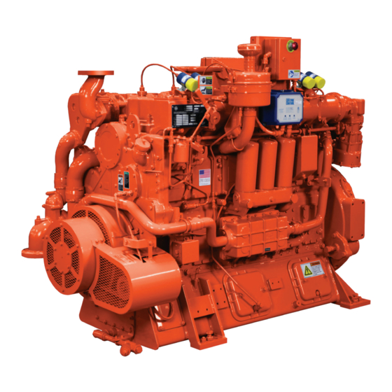
F18/H24 G/GL/GLD/GSID
Repair & Overhaul Manual
FORM 6243
Copyright 1989, 2001, 2002 Dresser, Inc. All rights
reserved
Waukesha Engine
Dresser, Inc.
Waukesha, Wisconsin 53188
Printed in U.S.A. 7/02
Printed on Recycled Paper
Serial No.
Specification No.
This document contains proprietary and trade secret information and
is given to the receiver in confidence. The receiver by reception and
retention of the document accepts the document in confidence and
agrees that, except as with the prior expressed written permission of
Waukesha Engine, Dresser, Inc., it will; (1) not use the document or any
copy thereof or the confidential or trade secret information
therein; (2) not copy or reproduce the document in whole, or in part
without the prior written approval of Waukesha Engine, Dresser, Inc.;
and (3) not disclose to others either the document or the confidential or
trade secret information contained therein.
All sales and information herein supplied subject to Standard Terms of
Sale, including limitation of liability.
WAUKESHA, DRESSER, and WKI are registered trademarks of
Dresser, Inc. VGF and DRESSER logo are trademarks of Dresser, Inc.
All other trademarks, service marks, logos, slogans, and trade names
(collectively "marks") are the properties of their respective owners.
Dresser, Inc. disclaims any proprietary interest in these marks owned
by others.
â
ä
Third Edition

Advertisement

Table of Contents
loading

Summary of Contents for Waukesha VGF F18G

  • Page 1 Waukesha Engine, Dresser, Inc., it will; (1) not use the document or any copy thereof or the confidential or trade secret information PLEASE NOTE: If grey lines appear therein;...
  • Page 2: Table Of Contents

    ILLUSTRATIONS LIST OF ILLUSTRATIONS Section 1.00 - - Warning Tag And Decal Figure 1.15-8. Right Side View -- H24GL ..1.15 -- 6 Locations Figure 1.15-9. Right Side View -- H24GLD, Impco Carburetor ..... 1.15 -- 7 Figure 1.00-1.
  • Page 3 ILLUSTRATIONS Figure 2.00-17. Cross Bar Installation ..2.00 -- 4 Figure 2.05-24. Camshaft And Idler Gear Removal ......2.05 -- 7 Figure 2.00-18.
  • Page 4 ILLUSTRATIONS Section 3.00 - - Cylinder Head Figure 3.00-41. Cross Bars And Seats ..3.00 -- 20 Figure 3.00-42. Rocker Cover Head Studs 3.00 -- 20 Figure 3.00-1. Rocker Arm Support ..3.00 -- 1 Figure 3.00-2.
  • Page 5 ILLUSTRATIONS Section 4.00 - - Crankcase Assembly Figure 4.00-39. Adapter Installed Inline With Wrench ......4.00 -- 13 Figure 4.00-1.
  • Page 6 ILLUSTRATIONS Figure 4.00-74. Intermediate Gear Hub ..4.00 -- 22 Figure 4.00-111. Flywheel Housing Installation ......4.00 -- 32 Figure 4.00-75.
  • Page 7 ILLUSTRATIONS Figure 4.05-28. CSA Flange Mounted Coil . . . 4.05 -- 8 Figure 5.00-20. Governor Rod ....5.00 -- 9 Figure 4.05-29. CSA High Tension Coil Lead 4.05 -- 8 Figure 5.00-21.
  • Page 8 ILLUSTRATIONS Figure 5.05-5. F18/H24 GLD Deltec Figure 5.05-43. GLD/GSID Turbo Air Inlet Fuel System ......5.05 -- 2 Connection .
  • Page 9 ILLUSTRATIONS Figure 5.05-76. Deltec Main Adjusting Figure 5.10-6. F18/H24 Magneto ... 5.10 -- 3 Screw ......5.05 -- 24 Figure 5.10-7.
  • Page 10 ILLUSTRATIONS Figure 5.10-46. Harness Ground Wire -- Figure 5.10-81. Hall--effect Pickup Right Rear ......5.10 -- 18 Installation .
  • Page 11 ILLUSTRATIONS Section 5.15 - - Air Induction System Figure 5.15-40. 4024 Governor ... . 5.15 -- 12 Figure 5.15-41. Throttle Valve ... . . 5.15 -- 12 Figure 5.15-1.
  • Page 12 ILLUSTRATIONS Figure 5.20-21. Garret Turbocharger ..5.20 -- 7 Figure 5.25-21. Auxiliary Water Pump Inspection ......5.25 -- 10 Figure 5.20-22.
  • Page 13 ILLUSTRATIONS Figure 5.25-57. Auxiliary Water Pump Figure 5.25-94. Intercooler Connection ..5.25 -- 30 Adapter ......5.25 -- 20 Figure 5.25-95.
  • Page 14 ILLUSTRATIONS Figure 5.25-128. Auxiliary Water Figure 5.30--25. Oil Cooler To Filter Thermostat ......5.25 -- 39 Connection .
  • Page 15 ILLUSTRATIONS Figure 5.30--62. Air/Gas Starter Motor ..5.30 -- 28 Figure 5.35-15. Breather Ejector ... . 5.35 -- 5 Figure 5.30--63. Air/Gas Starter Motor Figure 5.35-16. Exhaust Outlet Connections .
  • Page 16 ILLUSTRATIONS Figure 5.35-51. Wastegate Mounting Plate 5.35 -- 16 Figure 5.40-23. Ventilation System Baffle ....... . . 5.40 -- 9 Figure 5.35-52.
  • Page 17 ILLUSTRATIONS Figure 5.40-60. Air Duct Assembly ..5.40 -- 20 Figure 6.00-9. Instrument Panel Installation 6.00 -- 3 Figure 5.40-61. Oil Separator Drain Hose . . . 5.40 -- 20 Figure 6.00-10. Instrument Panel .
  • Page 18 ILLUSTRATIONS Figure 6.05-15. Current Junction Box Figure 6.10-27. F18/H24 Vibration Damper Mounting ......6.05 -- 6 Guard .
  • Page 19 TABLES LIST OF TABLES Section 1.00 - - Warning Tag And Decal Table 1.20-15. Cross Bar And Guide ..1.20 -- 13 Locations Table 1.20-16. Oil Pump ....1.20 -- 14 Table 1.20-17.
  • Page 20 TABLES Section 4.05 - - Cylinder Head Installation Table 5.30-5. VGF Sump And Header Temperatures And SAE Number ..5.30 -- 7 Table 4.05-1. Special Tools For Cylinder Table 5.30-6. Oil Consumption ... . . 5.30 -- 8 Head .
  • Page 21 ALWAYS BE ALERT FOR THE SPECIAL WARNINGS investment. In the industrial engine field the name, WITHIN THE MANUAL TEXT. THESE WARNINGS Waukesha Engine, stands for quality and durability. With PRECEDE INFORMATION THAT IS CRUCIAL TO normal care and maintenance this engine will provide YOUR SAFETY AS WELL AS OTHER PERSONNEL many years of reliable service.
  • Page 22: Table 1.00-1. Vgf 6 And 8 Cylinder Engine Safety Labels

    SECTION 1.00 WARNING TAG AND DECAL LOCATIONS WARNING TAG AND DECAL LOCATIONS NOTE: The decals and tags shown in this manual are for the current production engine. Your engine may have the previous tags or decals that are not shown. The previous tags will contain similar wordage and will be All warning tags and decals must be visible and located very close to the position of the new tags.
  • Page 23 WARNING TAG AND DECAL LOCATIONS P/N 211910K P/N 211930C P/N 211930A P/N 211910L P/N 305885 PLATE P/N 211900B P/N 211920E DELTEC Figure 1.00-1. Warning Tag And Decal Locations 1.00 - - 2 FORM 6243 Third Edition...
  • Page 24 WARNING TAG AND DECAL LOCATIONS P/N 211920E P/N 211900 P/N 211910N P/N 211910W P/N 211910T P/N 305884 BRACKET P/N 211911B P/N 211920B P/N 211910N P/N 211920E F18/H24G/GL P/N 211910N P/N 305886 PLATE P/N 211910N F18/H24G/GL P/N 211911J Figure 1.00-2. Warning Tag And Decal Locations 1.00 - - 3 FORM 6243 Third Edition...
  • Page 25: Figure 1.00-3. Caution Label -- P/N 209107M

    WARNING TAG AND DECAL LOCATIONS CAUTION CAUTION TO SERVICE HEATER 1. TURN POWER OFF 2. CLOSE SHUTOFF VALVES 3. DRAIN HEATER NOTE: OPEN VALVES BEFORE TURNING HEATER ON. 209107M Figure 1.00-3. Caution Label - - P/N 209107M - - To Service Heater Figure 1.00-6.
  • Page 26: Figure 1.00-9. Warning Label -- P/N 211910W

    WARNING TAG AND DECAL LOCATIONS Figure 1.00-9. Warning Label - - P/N 211910W - - Vent Flammable Gas Figure 1.00-10. Warning Label - - P/N 211911B - - Built Without Engine Protection Figure 1.00-12. Caution Label - - P/N 211920B - - Eye/Ear Protection Figure 1.00-11.
  • Page 27: Figure 1.00-13. Caution Label -- P/N 211920E

    WARNING TAG AND DECAL LOCATIONS Figure 1.00-13. Caution Label - - P/N 211920E - - Hot Components Figure 1.00-14. Safety Label - - P/N 211930A - - Lifting Instructions Figure 1.00-15. Caution Label - - P/N 211930C - - Lifting Instructions 1.00 - - 6 FORM 6243 Third Edition...
  • Page 28 All requirements of the Federal Occupational Safety and Health Act must be met when Waukesha products are operated in areas that are under the jurisdiction of the To avoid severe personal injury or death, all warning United States of America.
  • Page 29 SAFETY CHEMICALS GENERAL To avoid severe personal injury or death, ensure that all tools and other objects are removed from the unit and any driven equipment before restarting the unit. Always read and comply with safety labels on all containers. Do not remove or deface the container labels.
  • Page 30 SAFETY COOLING SYSTEM IGNITION Avoid contact with ignition units and wiring. Ignition Always wear protective clothing when venting, system components can store electrical energy and flushing or blowing down the cooling system. if contacted can cause electrical shocks. Electrical Operational coolant temperatures can range from shock can cause severe personal injury or death.
  • Page 31 SAFETY FUELS INTOXICANTS AND NARCOTICS GENERAL Do not allow anyone under the influence of intoxi- cants and/or narcotics to work on or around Ensure that there are no leaks in the fuel supply. industrial engines. Workers under the influence of Engine fuels are highly combustible and can ignite intoxicants and/or narcotics are a hazard both to or explode causing severe personal injury or death.
  • Page 32 SAFETY SPRINGS WEIGHT Always wear safety glasses when removing retain- Always consider the weight of the item being lifted ing (snap) rings. Verify the correct retaining ring and use only properly rated lifting equipment and pliers is used and the pliers is in good condition. If approved lifting methods.
  • Page 33: Figure 1.10-1. Correct Method Of Lifting

    SECTION 1.10 RIGGING AND LIFTING ENGINES RIGGING AND LIFTING ENGINE To avoid personal injury or death, follow approved rigging procedures to ensure no undue strain on the lifting eyes, chains and cables when lifting the engine. Attach the hook of the hoisting chain to the lifting eye. Exercise extreme care when moving the engine or Bring the chain straight up and attach to a certified its components.
  • Page 34 RIGGING AND LIFTING ENGINES LEFT SIDE VIEW RIGHT SIDE VIEW Figure 1.10-2. Correct Method Of Lifting Engine - - Side Views 1.10 - - 2 FORM 6243 Third Edition...
  • Page 35: Figure 1.15-1. Previous Production Model

    “draw--thru” fuel system. The MODELS turbocharger “draws” the air/fuel mixture from the Waukesha Engine, Dresser, Inc. manufactures two carburetors to the turbocharger, then forces the mixture models of VGF inline engines: the F18 and H24.
  • Page 36: Figure 1.15-2. Vgf Specification Plate

    Waukesha Knock Index COUNTER-CLOCKWISE ROTATION (WKI ), ignition timing, rated output in horsepower and FACING FLYWHEEL.
  • Page 37: Figure 1.15-5. Engine Serial Number

    CRANKSHAFT carburetion and the GLD and GSID models have draw through carburetion. Gas regulators are different de- Waukesha F18 and H24 engines rotate in the standard counterclockwise direction when facing the flywheel. pending on application and are generally engine The forged steel crankshaft is dynamically balanced mounted.
  • Page 38 GENERAL INFORMATION ENGINE IDENTIFICATION VIEWS LEFT SIDE VIEW 16 15 1. Exhaust Outlet 15. Engine Support 2. Turbocharger 16. Jack Screw 3. Control Panel 17. Oil Drain 4. Intake Manifold 18. Oil Filters 19. Oil Cooler 5. Lifting Eye 20. Auxiliary Water Thermostat 6.
  • Page 39 GENERAL INFORMATION 1. CEC Ignition Module 15. Oil Drain 2. Exhaust Outlet 16. Fuel Pressure Regulator 3. Instrument Panel 17. Auxiliary Water Piping 4. Lifting Eye 18. Oil Cooler 19. Oil Filters 5. Carburetor 20. CEC Junction Box 6. Air Cleaner 7.
  • Page 40 GENERAL INFORMATION RIGHT SIDE VIEW 1. Heat Shield 14. Auxiliary Water Piping 2. Exhaust Outlet 15. Engine Support 3. Wastegate 16. Jack Screw 4. Ignition Coils 17. Auxiliary Water Pump 5. Exhaust Manifold 18. Auxiliary Water Inlet 6. Jacket Water Thermostat Housing 19.
  • Page 41: Figure 1.15-9. Right Side View -- H24Gld

    GENERAL INFORMATION 1. Heat Shield 15. Engine Support 2. Exhaust Outlet 16. Jack Screw 3. Wastegate 17. Auxiliary Water Inlet 4. Exhaust Manifold 18. Auxiliary Water Piping 5. Ignition Coils 19. Water Header 6. Spark Plug Location 20. Fuel Inlet 7.
  • Page 42: Figure 1.15-10. Right Side View -- F18Gld

    GENERAL INFORMATION 1. Exhaust Outlet 13. Dip Stick 2. Heat Shield 14. Starter Motor Location 3. Wastegate 15. Oil Drain 4. Exhaust Manifold 16. Flywheel and Housing 5. Jacket Water Outlet 17. Breather Oil Separator 6. Lifting Eye 18. Intercooler 7.
  • Page 43 GENERAL INFORMATION 1. Exhaust Outlet 15. Auxiliary Water Pump 2. Heat Shield 16. Auxiliary Water Inlet 3. Wastegate 17. Auxiliary Water Piping 4. Exhaust Manifold 18. Water Header 5. Jacket Water Thermostat Housing 19. Dip Stick 6. Thermostat Housing Air Bleed 20.
  • Page 44 GENERAL INFORMATION FRONT VIEW 1. Exhaust Outlet 12. Oil Cooler 2. Jacket Water Outlet 13. Fuel Shutoff Valve 3. Spark Plug Location 14. Barring Device 4. Lifting Eye 15. Jack Screw 5. Ignition Coils 16. Engine Support 6. Breather Oil Separator 17.
  • Page 45 GENERAL INFORMATION 1. Exhaust Outlet 14. Oil Cooler 2. Turbocharger 15. Barring Device 3. Jacket Water Outlet 16. Engine Support 4. Turbocharger To Intercooler Air 17. Jack Screw Connection 18. Oil Pan 5. Spark Plug Location 19. Vibration Damper 6. Lifting Eye 20.
  • Page 46 GENERAL INFORMATION REAR VIEW 1. Exhaust Outlet 11. Auxiliary Water Piping 2. Turbocharger 12. Auxiliary Water Thermostat 3. Heat Shield 13. Timing Window 4. Air Cleaner 14. Fuel Inlet 5. Intercooler 15. Carburetor 6. Starter Motor Location 16. Instrument Panel 7.
  • Page 47 GENERAL INFORMATION 1. Exhaust Outlet 11. Fuel Pressure Regulator 2. Air Cleaner 12. Timing Window 3. Air Filter Restriction Indicator 13. Carburetor 4. Auxiliary Water Piping 14. Butterfly Valve 5. Starter Motor Location 15. Intake Manifold 6. Engine Support 16. Instrument Panel 7.
  • Page 48: Figure 1.15-16. Rear View -- F18G/H24G

    GENERAL INFORMATION 1. Exhaust Outlet 11. Fuel Shutoff Valve 2. Air Cleaner Assembly 12. Fuel Pressure Regulator 3. Air Filter Restriction Indicator 13. Timing Window 4. Carburetor 14. Butterfly Valve 5. Fuel Piping 15. Instrument Panel 6. Starter Motor Location 16.
  • Page 49 GENERAL INFORMATION INSTRUMENT PANEL GAUGES Lube Oil Temperature Switchgage: Monitors engine oil temperature at the oil filter housing (see Oil Pressure Switchgage: Monitors engine oil pres- Figure 1.15-17). This switchgage should be adjusted so sure at the main oil gallery (see Figure 1.15-17). This that the switchgage contacts close when the engine oil switchgage should be adjusted so that the switchgage temperature exceeds a setpoint as specified in Section...
  • Page 50: Table 1.15-1. Special Tools

    Crankcase Spreader Tool Table 1.15-1). In some instances, substitute items may 472007 Piston Removal Tool be used, but only if specifically approved by Waukesha. 472075 Piston Ring Expander To order these service tools, contact your local Wauke- sha Engine Distributor.
  • Page 51: Table 1.15-3. Model F18 And

    GENERAL INFORMATION Model F18 And H24 Specifications Table 1.15-3. Model F18 And H24G/GSID/GL/GLD Specifications GENERAL SPECIFICATIONS Engine Model Type 4- -cycle overhead valve 4- -cycle overhead valve Aspiration, G Naturally aspirated Naturally aspirated Aspiration, GL, GLD, GSID Turbocharged, intercooled Turbocharged, intercooled Number of cylinders Inline- -6, 4- -valves per cylinder Inline- -8, 4- -valves per cylinder...
  • Page 52 GENERAL INFORMATION GENERAL SPECIFICATIONS Engine Model Cooling System Jacket water capacity, engine only 16 gallons (60 litres) 20 gallons (75 litres) Auxiliary water capacity, engine only 6 gallons (23 litres) 6 gallons (23 litres) Maximum inlet head, water pump 28 ft. (8.5 m) 28 ft.
  • Page 53: Figure 1.15-18. Rear View F18Gl/H24Gl

    GENERAL INFORMATION TEMPERATURE AND PRESSURE TEST POINTS Refer to Figure 1.15-18, Figure 1.15-19 and Figure 1.15-20 for location of temperature and pressure test points on all VGF engines. Pressures Intake Manifold Carburetor Air Carburetor Fuel Crankcase Vacuum Temperatures Intake Manifold Exhaust Stack (Within 36²...
  • Page 54: Figure 1.15-19. Right And Left Side Views

    GENERAL INFORMATION P1, T1 LEFT SIDE VIEW P2, T2 RIGHT SIDE VIEW Pressures Temperatures P1 Intake Manifold T1 Intake Manifold P2 Exhaust Manifold T2 Exhaust Manifold P3 Exhaust Back Pressure T4 Oil P4 Oil T5 Jacket Water Outlet P5 Carburetor Air T6 Auxiliary Water Inlet P6 Carburetor Fuel P8 Crankcase Vacuum...
  • Page 55: Figure 1.15-20. Front View F18Gl/H24Gl

    GENERAL INFORMATION Pressures Carburetor Air Carburetor Fuel Crankcase Vacuum Temperatures Jacket Water Outlet Figure 1.15-20. Front View F18GL/H24GL, Impco TORQUE VALUES Table 1.15-4 lists common hex head screw torque specifications for the F18/H24 engine. Additional torque values are listed in Table 1.15-5 through Table 1.15-7. All torque values assume dry hex head screws, unless other wise noted (*oil lubricated).
  • Page 56: Figure 2.05-19. Damper Driving Flange

    GENERAL INFORMATION NEWTON- - FOOT-LBS METERS ITEM APPLICATION INSTRUCTIONS (ft-lb) (N×m) â Cam door (rear) Apply Loctite 242 M10 x 25 mm Apply Anti- -seize Carburetor to throttle body 5/16” Ferryhead Hex head screw â Gear Housing (inner hex head screws) Apply Loctite 242, M10 x 30 mm Coil screws (CSA shielded ignition)
  • Page 57: Figure 3.00-1. Rocker Arm Support

    GENERAL INFORMATION NEWTON- - FOOT-LBS METERS ITEM APPLICATION INSTRUCTIONS (ft-lb) (N×m) *37 ± 7 *50 ± 10 Main bearing cap crossbolt P/N 304818 *92 ± 7 *125 ± 10 Oil cooler/filter housing to crankcase Oil cooler/thermostatic valve flange connections Oil filler assembly to gear cover M8 x 22 mm Oil pump cover capscrews P/N 290393, M10 x 25 mm...
  • Page 58: Table 1.15-5. Metric Standard Capscrew Torque Values (Untreated Black Finish)

    GENERAL INFORMATION NEWTON- - FOOT-LBS METERS ITEM APPLICATION INSTRUCTIONS (ft-lb) (N×m) â Water pump cover screws 300061 Apply Loctite â Water pump idler assembly to gear cover Apply Loctite TORQUE VALUES Table 1.15-5. Metric Standard Capscrew Torque Values (Untreated Black Finish) COARSE THREAD CAPSCREWS (UNTREATED BLACK FINISH) PROPERTY 10.9...
  • Page 59: Table 1.15-6. Metric Standard Capscrew Torque Values (Electrically Zinc Plated)

    GENERAL INFORMATION Table 1.15-6. Metric Standard Capscrew Torque Values (Electrically Zinc Plated) COARSE THREAD CAPSCREWS (ELECTRICALLY ZINC PLATED) PROPERTY 10.9 12.9 CLASS SIZE TORQUE TORQUE TORQUE TORQUE N×m in-lb N×m in-lb N×m in-lb N×m in-lb 0.56 1.28 2.15 1.28 4.95 5.75 16.5 16.5...
  • Page 60: Table 1.15-7. U.s. Standard Capscrew Torque Values

    GENERAL INFORMATION Table 1.15-7. U.S. Standard Capscrew Torque Values GRADE NUMBER NUMBER Grade 1 or 2 Grade 5 Grade 8 SIZE/ TORQUE TORQUE TORQUE THREADS in-lb (N×m) in-lb (N×m) in-lb (N×m) PER INCH THREADS OILED PLATED OILED PLATED OILED PLATED 1/4 - - 20 62 (7) 53 (6)
  • Page 61: Table 1.15-9. English To Metric Formula Conversion Table

    GENERAL INFORMATION Table 1.15-9. English To Metric Formula Conversion Table CONVERSION FORMULA EXAMPLE Inches and any fraction in decimal equivalent Inches to Millimeters 2-5/8 in. = 2.625 x 25.4 = 66.7 mm multiplied by 25.4 equals millimeters. Cubic Inches to Litres Cubic inches multiplied by 0.01639 equals litres.
  • Page 62: Figure 5.25-132. High Temperature

    â Perma Lok Heavy Duty Pipe Sealant with Teflon or its equivalent). Waukesha does not endorse one brand The following is a list of sealants, adhesives and over another. In all cases, equivalent products may be lubricants (see Table 1.15-11) required to perform the substituted for the brand name listed.
  • Page 63: Table 1.20-1. Cylinder Liner

    SECTION 1.20 SPECIFICATIONS SPECIFICATIONS Table 1.20-1. Cylinder Liner WEAR LIMIT NEW MINIMUM NEW MAXIMUM in. (mm) in. (mm) in. (mm) (A) Flange height 0.550 (13.97) 0.5512 (14.001) 0.552 (14.021) (B) Liner protrusion above crankcase 0.000 (0.000) 0.0027 (0.069) 0.0047 (0.119) (C) Liner ID 5.991 (152.171) 5.984 (151.993)
  • Page 64: Table 1.20-2. Crankcase

    SPECIFICATIONS Table 1.20-2. Crankcase WEAR LIMIT NEW MINIMUM NEW MAXIMUM in. (mm) in. (mm) in. (mm) (A) Liner counterbore diameter 7.4547 (189.350) 7.4508 (189.250) 7.4547 (189.350) (B) Liner counterbore depth 0.5502 (13.975) 0.5512 (14.000) 0.5530 (14.046) (C) Crankcase upper bore 6.9110 (175.540) 6.9094 (175.500) 6.9110 (175.540)
  • Page 65: Table 1.20-3. Piston

    SPECIFICATIONS Table 1.20-3. Piston Piston Material: Cast aluminum alloy (skirt is treated with “Graffal 20”, a gray phosphate lubricant for break--in). Piston Type: Cam ground Pistons are remove from: Top of the crankcase. Permissible piston weight: 3704 to 3781 grams (131 to 133 oz.) GL/GLD Compression ratio: 11:1 (GL LCR Compression ratio 8.7:1) G/GSID Compression ratio: 8.6:1 WEAR LIMIT...
  • Page 66: Table 1.20-5. Piston Rings

    SPECIFICATIONS Table 1.20-5. Piston Rings Top ring: Barrel--faced chrome plated, compression (top is marked “TOP”). Second ring: Tapered face compression (top marked with a dot for “TOP” or “UP”). Third ring: Conformable grooved oil ring with expander. WEAR LIMIT NEW MINIMUM NEW MAXIMUM in.
  • Page 67 SPECIFICATIONS Table 1.20-6. Crankshaft WEAR LIMIT NEW MINIMUM NEW MAXIMUM in. (mm) in. (mm) in. (mm) Crankshaft endplay 0.0300 (0.762) 0.0138 (0.350) 0.0250 (0.636) Thrust ring thickness (standard) 0.1328 (3.373) 0.1378 (3.500) 0.1409 (3.580) (A) Connecting rod bearing running clearance 0.0110 (0.279) 0.0033 (0.083) 0.0069 (0.176)
  • Page 68: Table 1.20-7. Camshaft Followers

    SPECIFICATIONS Table 1.20-7. Camshaft Followers SHAFT PUSHROD SEAT SNAP RING BUSHING OUTER ROLLER WEAR LIMIT NEW MINIMUM NEW MAXIMUM in. (mm) in. (mm) in. (mm) Bushing ID 1.263 (32.08) 1.2602 (32.01) 1.261 (32.03) Shaft OD 1.2579 (31.95) 1.2595 (31.991) 1.2597 (31.996) Pin OD 0.6276 (15.94) 0.6287 (15.97)
  • Page 69: Table 1.20-8. Valve Spring Clearances

    SPECIFICATIONS Table 1.20-8. Valve Spring Clearances OUTER (A) INNER (B) Wire diameter 0.177 in. (4.5 mm) 0.133 in. (3.4 mm) Number of coils 41.8 -- 48.1 lb. @ 2.118 in. 18.5 -- 21.6 lb @ 1.921 in. Load at specified length (valve closed) (19 -- 21.8 kg @ 53.8 mm) (8.4 -- 9.8 kg @ 48.8 mm) 90.4 -- 99.3 lb @ 1.539 in.
  • Page 70: Table 1.20-9. Flywheel And Housing

    SPECIFICATIONS Table 1.20-9. Flywheel And Housing MAXIMUM in. (mm) (A) Face run out on flywheel 0.013 (0.330) (B) Pilot bore run--out 0.005 (0.127) (C) Housing bore run--out 0.010 (0.254) (D) Housing face run--out 0.010 (0.254) 1.20 - - 8 FORM 6243 Third Edition...
  • Page 71: Table 1.20-10. Connecting Rod, Bushing And

    SPECIFICATIONS Table 1.20-10. Connecting Rod, Bushing And Bearing WEAR LIMIT NEW MINIMUM NEW MAXIMUM in. (mm) in. (mm) in. (mm) Rod material -- Heat treated steel forging Permissible variation 21.16 ± 0.10 lb. (9600 ± 45 grams) (A) Rod Length, center to center 12.204 (309.981) 12.204 (309.981) 12.2047 (310.0)
  • Page 72: Table 1.20-11. Valve Clearances

    SPECIFICATIONS Table 1.20-11. Valve Clearances WEAR LIMIT NEW MINIMUM NEW MAXIMUM in. (mm) in. (mm) in. (mm) (A) Valve length Intake 7.597 (192.963) 7.607 (193.22) 7.629 (193.78) Exhaust 7.597 (192.963) 7.607 (193.22) 7.629 (193.78) (B) Valve stem diameter Intake 0.429 (10.910) 0.430 (10.936) 0.431 (10.954) Exhaust...
  • Page 73: Table 1.20-12. Cylinder Head Clearances

    SPECIFICATIONS Table 1.20-12. Cylinder Head Clearances WEAR LIMIT NEW MINIMUM NEW MAXIMUM in. (mm) in. (mm) in. (mm) (A) Valve guide ID Intake 0.4365 (11.087) 0.4343 (11.023) 0.4346 (11.040) Exhaust 0.4365 (11.087) 0.4343 (11.023) 0.4346 (11.040) Valve Guide ID to stem OD Clearance Intake 0.0003 (0.0076) 0.003 (0.076)
  • Page 74: Table 1.20-13. Rocker Arm Assemblies

    SPECIFICATIONS Table 1.20-13. Rocker Arm Assemblies EXHAUST ROCKER ARM INTAKE ROCKER ARM WEAR LIMIT NEW MINIMUM NEW MAXIMUM in. (mm) in. (mm) in. (mm) (A) Rocker arm shaft OD 1.2579 (31.950) 1.2589 (31.976) 1.2595 (31.991) (B) Rocker arm bushing ID (ream to ID) 1.262 (32.055) 1.260 (32.009) 1.261 (32.034)
  • Page 75: Table 1.20-14. Camshaft

    SPECIFICATIONS Table 1.20-14. Camshaft WEAR LIMIT NEW MINIMUM NEW MAXIMUM in. (mm) in. (mm) in. (mm) (A) Camshaft bearing journal diameter 2.6723 (67.8764) 2.6736 (67.9094) 2.675 (67.940) (B) Camshaft bearing journal running clearance 0.008 (0.203) 0.002 (0.051) 0.005 (0.127) Camshaft endplay 0.011 (0.279) 0.004 (0.101) 0.006 (0.152)
  • Page 76 SPECIFICATIONS Table 1.20-16. Oil Pump WEAR LIMIT NEW MINIMUM NEW MAXIMUM in. (mm) in. (mm) in. (mm) (A) Oil pump pressure gear backlash 0.012 (0.304) 0.0055 (0.139) 0.008 (0.203) (B) Pressure gear to cover endplay 0.012 (0.304) 0.0055 (0.139) 0.008 (0.203) (C) Drive shaft bushing ID 1.1839 (30.071) 1.1810 (29.997)
  • Page 77: Table 1.20-17. Front Gear Train Backlash

    SPECIFICATIONS Table 1.20-17. Front Gear Train Backlash WEAR LIMIT NEW MINIMUM NEW MAXIMUM in. (mm) in. (mm) in. (mm) (A) Oil Pump Intermediate (Idler) To 0.010 (0.254) 0.006 (0.15) 0.013 (0.33) Oil Pump Gear (B) Oil Pump Intermediate (Idler) To Crankshaft 0.010 (0.254) 0.006 (0.15) 0.014 (0.35)
  • Page 78: Figure 3.00-19. Valve Seat

    SPECIFICATIONS Table 1.20-18. Valve Seat Clearances NEW MINIMUM NEW MAXIMUM in. (mm) in. (mm) (A) Valve seat insert OD Intake 2.169 (55.102) 2.170 (55.118) Exhaust 2.169 (55.102) 2.170 (55.118) (B) Valve seat insert ID Intake 1.740 (44.20) 1.764 (44.80) Exhaust 1.740 (44.20) 1.764 (44.80) (C) P/N 304010K Valve seat insert height...
  • Page 79: Figure 2.00-1. Exhaust Thermocouple

    SECTION 2.00 CYLINDER HEAD REMOVAL Table 2.00-1. Special Tools For Cylinder Head TOOL P/N TOOL DESCRIPTION 472015 Rocker Arm Support/Manifold Wrench 472065 Spark Plug Tube Retaining Tool CYLINDER HEAD REMOVAL NOTE: Individual cylinder heads can be removed without removing the intake or exhaust manifolds. Always shut off the fuel supply and clear the engine THERMOCOUPLE supply lines and piping of accumulated gas prior to...
  • Page 80: Figure 2.00-4. Turbocharger Discharge

    CYLINDER HEAD REMOVAL 9. Non CSA—Remove spark plug. Tool M12 X 35 mm P/N 472065 to hold spark plug tube while removing HEX HEAD SCREWS spark plug (see Figure 2.00-7). Figure 2.00-4. Turbocharger Discharge Elbow TUBE (SPARK PLUG) 7. Remove turbocharger heat shield if required (see Figure 2.00-7.
  • Page 81: Figure 2.00-9. Csa High Tension Lead

    CYLINDER HEAD REMOVAL 15. CSA—Remove four hex nuts and lock washers from rocker arm cover (see Figure 2.00-12). HIGH TENSION LEAD NUTS NUTS Figure 2.00-9. CSA High Tension Lead 12. CSA—Remove M8 x 20 mm hex head screws from flange mounted ignition coil (see Figure 2.00-10). Figure 2.00-12.
  • Page 82: Figure 2.00-14. Rocker Arm Support Installation

    CYLINDER HEAD REMOVAL 21. Remove push rods. Record location. M10 X 110 mm HEX HEAD SCREWS 22. Remove cross bar seats and cross bars from cylinder head (see Figure 2.00-17). 23. Remove rocker arm cover recess tube. ROCKER ARM COVER RECESS SEAT TUBE...
  • Page 83: Figure 2.00-19. Intake Manifold

    CYLINDER HEAD REMOVAL 25. Remove governor regulating shaft if it interferes with cylinder head removal (see Figure 2.00-19). GOVERNOR REGULATING SHAFT U- -BOLT Figure 2.00-21. CSA Conduit 29. Remove vortox separator bracket if it interferes with cylinder head removal (see Figure 2.00-22). Figure 2.00-19.
  • Page 84: Figure 2.00-24. Previous-Water Elbow Assembly

    CYLINDER HEAD REMOVAL 31. Previous Engines—Remove four M10 x 35 mm hex head screws and remove water elbow (see Figure 2.00-24). M10 X 35 mm HEX HEAD SCREWS M10 X 35 mm HEX HEAD SCREWS CYLINDER HEAD NUT AND WASHER Figure 2.00-26.
  • Page 85 CYLINDER HEAD REMOVAL 36. Lift cylinder head off crankcase head studs at an angle that closely approximates the angle of the GASKET crankcase. Cylinder heads weigh 80 lb. (36 kg) each. Lift only with properly rated lifting device. Position the cylinder heads on a wooden board or pallet.
  • Page 86: Figure 2.05-1. Connecting Rod Inspection Cover

    SECTION 2.05 CRANKCASE COMPONENT REMOVAL Table 2.05- -1. Special Tools For Crankcase NOTE: Engine may contain a copper washer that is installed with the M14 hollow screw. If the piston cooling TOOL P/N TOOL DESCRIPTION jet contains a copper washer make sure it is installed 472007 Piston Removal Tool during assembly.
  • Page 87: Figure 2.05-3. Connecting Rod Access

    CRANKCASE COMPONENT REMOVAL Avoid scraping too deep CONNECTING into the cylinder liner ROD BOLT bore when removing the carbon ridge. Cutting too deep into the cylinder liner bore could damage the ring travel zone. Disregarding this information could result in product damage. CONNECTING ROD CAP Figure 2.05-3.
  • Page 88: Figure 2.05-7. Piston Removal

    CRANKCASE COMPONENT REMOVAL 3. Tighten center nut until liner is pulled from crankcase (see Figure 2.05-9). CENTER NUT CYLINDER HEAD STUDS CYLINDER LINER Figure 2.05-7. Piston Removal 8. Place rod cap on connecting rod and secure with connecting rod bolt. Verify rod cap and connecting rod are a matched set.
  • Page 89: Figure 2.05-11. Upper Oil Separator Inlet Tube

    CRANKCASE COMPONENT REMOVAL FRONT GEAR HOUSING REMOVAL OIL SUPPLY TUBE 1. Remove breather system connection from right side gear housing, if equipped (see Figure 2.05-11). HEX NUTS ADAPTER RETAINER Figure 2.05-13. Water Pump Idler Oil Supply 4. Remove governor and drive from rear of gear housing (see Figure 2.05-14).
  • Page 90: Figure 2.05-16. Hall--Effect Pickup Location

    CRANKCASE COMPONENT REMOVAL 6. Remove Hall--effect pickup (if equipped with CEC 8. Remove one upper M12 socket screw and install ignition) from front gear housing (see M12 guide pin (see Figure 2.05-18). Figure 2.05-16). See Section 5.10 Ignition System - - CEC/Magneto for complete information.
  • Page 91: Figure 2.05-20. Crankcase Seal Removal

    CRANKCASE COMPONENT REMOVAL Crankshaft Front Seal Replacement 3. Remove M10 hex head screws that secure cover to gear housing. Remove M10 socket head screws that 1. Use a rolling pry bar to pull seal out of gear cover attach base of cover to oil pan. (see Figure 2.05-20).
  • Page 92: Figure 2.05-24. Camshaft And Idler Gear

    CRANKCASE COMPONENT REMOVAL 5. Remove camshaft, intermediate gear and water pump LIFTING DEVICE idler gears from gear housing (see Figure 2.05-24). DOWELS Figure 2.05-26. Front Gear Housing 8. Remove front crankshaft gear (see Figure 2.05-27). Figure 2.05-24. Camshaft And Idler Gear Removal The front gear housing weighs 98 lb.
  • Page 93: Figure 2.05-29. Rear Engine Support

    CRANKCASE COMPONENT REMOVAL ENGINE SUPPORTS REMOVAL FLYWHEEL AND FLYWHEEL HOUSING REMOVAL 1. Disconnect and remove starter from flywheel hous- ing (see Figure 2.05-31). See Section 5.45 Starting With the prior components removed the six cylinder System in this manual for complete information. crankcase assembly weighs approximately 2,500 lb.
  • Page 94: Figure 2.05-33. Flywheel Removal

    CRANKCASE COMPONENT REMOVAL Crankshaft Rear Seal Replacement The crankshaft rear seal carrier can be removed without removing the flywheel housing. 1. Use a puller and M10 hex head screws to remove two alignment dowels. Remove rear seal carrier hex head screws from back of crankcase. Remove oil pan hex head screws from carrier (see Figure 2.05-35).
  • Page 95: Figure 2.05-37. Rear Seal Carrier

    CRANKCASE COMPONENT REMOVAL CAM GEAR HOLE Figure 2.05-39. Camshaft Thrust Flange DOWEL LOCATIONS 1. Remove oil filters and baffle box from crankcase Figure 2.05-37. Rear Seal Carrier Installation (see Figure 2.05-40). CAMSHAFT AND FOLLOWERS REMOVAL NOTE: The camshaft may be removed without removing the pivot shafts and cam followers by making an auxiliary rocker shaft arm holder tool (see Figure 2.05-38).
  • Page 96: Figure 2.05-42. Camshaft Access Doors

    CRANKCASE COMPONENT REMOVAL 3. Remove all camshaft access doors from crankcase (see Figure 2.05-42). REAR CAM COVER Figure 2.05-44. Rear Camshaft Cover CAMSHAFT DOOR 6. Remove hex nuts and socket head set screw (5 mm) that secure each rocker arm shaft (see Figure 2.05-45). Figure 2.05-42.
  • Page 97: Figure 2.05-46. Rocker Arm Shaft

    CRANKCASE COMPONENT REMOVAL 9. Thread camshaft removal/installation pilot tool, P/N 472024, into rear of camshaft (see Figure 2.05-48 WRENCH and Figure 2.05-49). NOTE: Tool P/N 472024 can be used only if the flywheel housing has been removed. TOOL CAMSHAFT Figure 2.05-46. Rocker Arm Shaft Removal Figure 2.05-48.
  • Page 98: Figure 2.05-50. Lube Oil Leveler

    CRANKCASE COMPONENT REMOVAL 3. Remove fuel regulator support bracket from oil pan (see Figure 2.05-53). VENT TUBE SUPPORT BRACKET Figure 2.05-50. Lube Oil Leveler Figure 2.05-53. Fuel Regulator Support Bracket VENT TUBE 4. Mark location and remove air/gas starter piping support bracket from oil pan (see Figure 2.05-54).
  • Page 99: Figure 2.05-55. Oil Pan Removal

    CRANKCASE COMPONENT REMOVAL Do not sp read the cran kcase more than 0.006 in. (0.15 mm). Use a dial indicator to measure the spread of the crankcase sides. Disregarding this information could result in product damage. 3. Install crankcase spreader tool P/N 472002 (see Figure 2.05-57) between bearing caps #1 and #2.
  • Page 100: Figure 2.05-59. Bearing Cap Crossbolt

    CRANKCASE COMPONENT REMOVAL 6. Left side #5 and #6 crossbolts have special washers 1. Use a puller with an M8 capscrew to remove smaller and O--rings (see Figure 2.05-59). These crossbolts plugs from crankcase (see Figure 2.05-61). Remove pass through oil passages and must be reinstalled in and discard O--rings on plug.
  • Page 101: Figure 3.00-2. Rocker Arm Support Wrench

    SECTION 3.00 CYLINDER HEAD DISASSEMBLY AND OVERHAUL Table 3.00-1. Special Tools For Cylinder Head 2. Use rocker arm support wrench (P/N 472015) and remove M10 x 35 mm hex head screws. Remove rocker TOOL P/N TOOL DESCRIPTION arm stand from cylinder head (see Figure 3.00-2 and 472068 Spark Plug Tube Socket Figure 3.00-3).
  • Page 102: Figure 3.00-4. Intake And Exhaust Rocker

    CYLINDER HEAD DISASSEMBLY AND OVERHAUL ROCKER ARM SHAFT EXHAUST ROCKER ARM INTAKE ROCKER ARM Figure 3.00-4. Intake and Exhaust Rocker Arms Table 3.00-2. Rocker Arm Assemblies WEAR LIMIT NEW MINIMUM NEW MAXIMUM in. (mm) in. (mm) in. (mm) (A) Rocker arm shaft OD 1.2579 (31.950) 1.2589 (31.976) 1.2595 (31.991)
  • Page 103: Figure 3.00-5. Cross Bars And Seats

    CYLINDER HEAD DISASSEMBLY AND OVERHAUL CROSS BAR INSPECTION Table 3.00-3. Cross Bar ID Specifications WEAR LIMIT NEW MINIMUM NEW MAXIMUM NOTE: Cross bars must be installed in their original in. (mm) in. (mm) in. (mm) positions. Mark or label the cross bars to prevent them 0.555 (14.097) 0.5531 (14.050) 0.5542 (14.077)
  • Page 104: Table 3.00-5. Cross Bar To Guide Clearance

    CYLINDER HEAD DISASSEMBLY AND OVERHAUL 6. Compare recorded cross bar guide OD to cross bar ROCKER ARM ASSEMBLY ID. If difference exceeds specification, replace parts as NOTE: Both the exhaust rocker arm and intake rocker needed (see Table 3.00-5). arm use the same assembly procedure. Table 3.00-5.
  • Page 105: Figure 3.00-10. Rocker Arm Support

    CYLINDER HEAD DISASSEMBLY AND OVERHAUL NOTE: The set screw does not lock the ball socket to INTAKE VALVE EXHAUST VALVE the rocker arm. The set screw is used for blocking the ROCKER ARM ROCKER ARM end of the rocker arm oil passage. â...
  • Page 106: Figure 3.00-12. Cylinder Head Face

    CYLINDER HEAD DISASSEMBLY AND OVERHAUL CYLINDER HEAD INSPECTION NOTE: Use Magnafluxä to inspect the cylinder heads for cracks whenever they are removed from the engine. Contact a local machine shop to have the heads Magnafluxä inspected. 1. Clean gasket surface and remove any foreign material from cylinder head (see Figure 3.00-12).
  • Page 107: Figure 3.00-16. Valve Split Locks

    CYLINDER HEAD DISASSEMBLY AND OVERHAUL 1. Compress valve springs and remove valve split locks (keepers). VALVE SPLIT LOCKS VALVE STEM SEAL VALVE VALVE SPRING COMPRESSOR Figure 3.00-18. Valve Removal Figure 3.00-16. Valve Split Locks 4. Remove valve spring seat (see Figure 3.00-19). NOTE: Valve components must be installed in their original positions.
  • Page 108: Figure 3.00-21. Valve Guide Removal Tool

    CYLINDER HEAD DISASSEMBLY AND OVERHAUL NOTE: Valve guides can only be removed by pressing · Heat fatigue them from the bottom of the cylinder head. Place · Breaks cylinder head in hydraulic press upside down to press guides out. · Wear 2.
  • Page 109: Figure 3.00-22. Valve Rework Dimensions

    CYLINDER HEAD DISASSEMBLY AND OVERHAUL Heat fatigue (overheating) can cause valve head NOTE: The valve face or stem may be ground in an cracking and breakage. Causes of heat fatigue include: attempt to resurface or remanufacture a worn valve. If the resurfaced valve exceeds the specifications listed, ·...
  • Page 110: Table 3.00-7. Valve Clearances

    CYLINDER HEAD DISASSEMBLY AND OVERHAUL Table 3.00-7. Valve Clearances 0.4313 in. — 0.4306 in. (10.954 mm — 10.936 mm) 0.421 in. — 0.413 in. (10.70 mm — 10.50 mm) 0.091 in. (2.4 mm) 2.051 in. — 2.043 in. 70°30¢ (52.10 mm — 51.90 mm) ±15¢...
  • Page 111: Table 3.00-8. Valve Guide Clearances

    CYLINDER HEAD DISASSEMBLY AND OVERHAUL Table 3.00-8. Valve Guide Clearances WEAR LIMIT NEW MINIMUM NEW MAXIMUM in. (mm) in. (mm) in. (mm) (A) Valve Guide ID Intake 0.4365 (11.087) 0.434 (11.023) 0.435 (11.049) Exhaust 0.4365 (11.087) 0.434 (11.023) 0.435 (11.049) Valve Guide ID to Stem OD Clearance Intake 0.0003 (0.0076)
  • Page 112: Figure 3.00-23. Valve Guide Installation

    CYLINDER HEAD DISASSEMBLY AND OVERHAUL TOP OF TOOL (P/N 472009) CYLINDER HEAD Comply with the liquid nitrogen/Dry Ice manufactur- SPRING er’s recommendations for proper use and handling SEAT AREA of liquid nitrogen/Dry Ice. Improper handling or use VALVE GUIDE of liquid nitrogen/Dry Ice will result in severe personal injury or death.
  • Page 113: Figure 3.00-24. Valve Seat Installation Tool

    NOTE: The pilot mandrel allows each valve seat to be ground concentric with the valve guide. The pilot mandrels (P/N 472035) supplied by Waukesha Engine are made only for use with the Hall- -Toledo EDP Valve Seat Grinder.
  • Page 114: Figure 3.00-27. Measure Valve Seat

    CYLINDER HEAD DISASSEMBLY AND OVERHAUL Table 3.00-9. Valve Seat Insert Grinding Stones TYPE STONE ANGLE TOOL P/N Seat Angle 20 Degrees 494014 TIGHTEN PILOT MANDREL NOTE: Install a fine grit stone or dress the stone with fine compound to perform the final grinding. 5.
  • Page 115: Table 3.00-10. Valve Seat Clearances

    CYLINDER HEAD DISASSEMBLY AND OVERHAUL Table 3.00-10. Valve Seat Clearances NEW MINIMUM NEW MAXIMUM in. (mm) in. (mm) (A) Valve seat insert OD Intake 2.169 (55.102) 2.170 (55.121) Exhaust 2.169 (55.102) 2.170 (55.121) (B) Valve seat insert ID Intake 1.740 (44.20) 1.764 (44.80) Exhaust 1.740 (44.20)
  • Page 116: Table 3.00-11. Valve Spring Clearances

    CYLINDER HEAD DISASSEMBLY AND OVERHAUL Table 3.00-11. Valve Spring Clearances OUTER (A) INNER (B) Wire diameter 0.177 in. (4.5 mm) 0.133 in. (3.4 mm) Number of coils 41.8 -- 48.1 lb. @ 2.118 in. 18.5 -- 21.6 lb @ 1.921 in. Load at specified length (valve closed) (19 -- 21.8 kg @ 53.8 mm) (8.4 -- 9.8 kg @ 48.8 mm)
  • Page 117: Figure 3.00-29. Expander Plug Location

    CYLINDER HEAD DISASSEMBLY AND OVERHAUL 1. Drill expander plug out with a carbide tipped drill. WATER JET INSTALLATION Sleeve must be completely removed. Use a “pick” to â 1. Apply Loctite 271 to outside edge of water jet. Install remove any remaining pieces. water jet with opening facing exhaust valves.
  • Page 118: Figure 3.00-33. Spark Plug Holder Seal

    CYLINDER HEAD DISASSEMBLY AND OVERHAUL 3. Place seal washer onto bottom of spark plug tube Oil on the valve stem is controlled by new “barbed” â (see Figure 3.00-33). Apply Loctite RCä 620, seals. Different seals are used on the intake and â...
  • Page 119: Figure 3.00-36. Valve Stem Seal Installation Tool

    CYLINDER HEAD DISASSEMBLY AND OVERHAUL 1. Lightly lubricate valve stems with molybdenum â grease (Citgo Lithoplex #2 grease or the equivalent). Insert valves into cylinder head. NOTE: Use tool P/N 472077 to install Blue Intake Valve Stem Seal (P/N 304015C) and Black Exhaust Valve Stem Seal P/N 304015B.
  • Page 120: Figure 3.00-39. Valve Spring Compressor

    CYLINDER HEAD DISASSEMBLY AND OVERHAUL CROSS BAR INSTALLATION NOTE: The cross bars and seats are installed only after Use caution when removing or installing the valve the cylinder head is installed and secured with hex nuts. springs. They are under tension and can eject from 1.
  • Page 121: Table 3.05-1. Crankcase Tools

    SECTION 3.05 CRANKCASE DISASSEMBLY AND OVERHAUL Table 3.05-1. Crankcase Tools TOOL P/N TOOL DESCRIPTION Be sure you have read and understood the safety 472002 Crankcase Spreader Tool and warning information in Section 1.05 Safety and 494278 Dial Indicator Section 1.10 Rigging And Lifting Engines, before 472013 Cylinder Liner Installation/Removal Tool proceeding.
  • Page 122: Figure 3.05-1. Crankshaft Set Screws

    CRANKCASE DISASSEMBLY AND OVERHAUL CRANKCASE INSPECTION SET SCREW The crankcase should be thoroughly checked for BORE cracks. Special attention should be paid to the area between the cylinders. Cracks may be detected by using a dye penetrant. The lower cylinder liner seal area in the cylinder block must be checked.
  • Page 123: Figure 3.05-2. 12 Cylinder Crankshaft

    Small surface cracks (a few thousandths of an be performed by a firm specializing in such work. inch deep) in the journals can be ground out. The Contact your distributor or Waukesha Engine’s Service â crankshaft must be checked with Magnaflux...
  • Page 124 CRANKCASE DISASSEMBLY AND OVERHAUL 2. Grind crankshaft journals to new maximum OD as Crankshaft Counterweights specified in Table 3.05-13. There should be approxi- mately 0.060 in. (1.524 mm) of chrome plate remaining. Crankshaft main and rod journals should be finished to a “12 RMS”...
  • Page 125: Figure 3.05-3. Crankshaft

    CRANKCASE DISASSEMBLY AND OVERHAUL LOCATION COUNTERWEIGHT NUMBERS BOLT CRANKSHAFT HARDENED WASHER Figure 3.05-3. Crankshaft 3. Verify counterweight and crankshaft cheek are CAMSHAFT stamped with identical location numbers (see CAMSHAFT CLEANING AND INSPECTION Figure 3.05-3). Rep lace all camsh af t follow er assemblies when a new camshaft is installed.
  • Page 126: Figure 3.05-4. Inspect Cam Followers

    CRANKCASE DISASSEMBLY AND OVERHAUL Table 3.05-2. Camshaft WEAR LIMIT NEW MINIMUM NEW MAXIMUM in. (mm) in. (mm) in. (mm) (A) Camshaft bearing journal diameter 2.6723 (67.8764) 2.6736 (67.9094) 2.675 (67.940) (B) Camshaft bearing journal running clearance 0.008 (0.203) 0.002 (0.051) 0.005 (0.127) Camshaft endplay 0.011 (0.279)
  • Page 127: Figure 3.05-5. Camshaft Follower

    CRANKCASE DISASSEMBLY AND OVERHAUL Compressed air can pierce the skin and cause Always wear safety glasses when removing retain- severe injury. Never use your hand to check for ing (snap) rings. Verify the correct retaining ring leaks or to determine air flow rates. Wear safety pliers is used and it is in good condition.
  • Page 128: Figure 3.05-7. Piston Pin

    CRANKCASE DISASSEMBLY AND OVERHAUL Table 3.05-3. Camshaft Follower Tolerances WEAR LIMIT NEW MINIMUM NEW MAXIMUM SPECIFICATION in. (mm) in. (mm) in. (mm) Rocker Arm Bushing ID 1.263 (32.08) 1.2602 (32.01) 1.261 (32.03) Rocker Arm Shaft OD 1.2579 (31.95) 1.2595 (31.991) 1.2597 (31.996) Camshaft Follower Pin OD 0.6276 (15.94)
  • Page 129: Figure 3.05-9. Piston Oil Drain Holes

    CRANKCASE DISASSEMBLY AND OVERHAUL PISTON CLEANING AND INSPECTION Exercise care to avoid scratching the sides of the piston ring grooves. Disregarding this informa- Do not sand blast or tion could result in product damage. glass bead pistons. Sand and glass bead blasting removes the tin plating and 2.
  • Page 130: Table 3.05-4. Piston Tolerances

    5.9579 (151.33) 5.963 (151.46) Use the published wear limits with discretion. Although Waukesha recognizes that many used Never operate an engine with a cracked piston. parts are suitable for continued service, there is Operating an engine with a cracked piston could...
  • Page 131: Figure 3.05-10. Check Piston Ring Groove

    CRANKCASE DISASSEMBLY AND OVERHAUL 13. Insert feeler gauge between ring upper surface and ring land. Measure and record ring groove side PISTON clearance. 14. Measure and record ring groove side clearance at NEW PISTON RING several locations around piston circumference. 15.
  • Page 132: Figure 3.05-11. Piston Pin

    CRANKCASE DISASSEMBLY AND OVERHAUL PISTON RING INSPECTION Table 3.05-6 and Figure 3.05-11 for piston pin specifi- cations. Discard pin if it exceeds limits. Perform the following checks before installing the piston rings. See Section 4 Crankcase Component Assembly for piston ring installation procedures. Do not install used (more than 50 hours run- ning time) piston rings.
  • Page 133: Figure 3.05-12. Connecting Rod

    CRANKCASE DISASSEMBLY AND OVERHAUL 4. Install connecting rod cap and secure with connecting · If the difference between point “B” and the average of rod bolts and washers (see Figure 3.05-12.). Lubricate “A” and “C” (A + C divided by 2) exceeds 0.002 in. bolt threads and washer faces with clean engine oil and (0.05 mm), rod is unusable (use Table 3.05-8 for tighten to 310 ±15 ft-lb (420 ±...
  • Page 134: Figure 3.05-14. Connecting Rod Bushing Press Removal

    CRANKCASE DISASSEMBLY AND OVERHAUL Table 3.05-9. Connecting Rod, Bushing And Bearing WEAR LIMIT NEW MINIMUM NEW MAXIMUM in. (mm) in. (mm) in. (mm) Rod material--Heat treated steel forging Permissible variation 21.16 ± 0.10 lb. (9600 ± 45 grams) (A) Rod length, center to center 12.204 (309.981) 12.204 (309.981) 12.2047 (310.00)
  • Page 135: Figure 3.05-15. Connecting Rod Bushing

    CRANKCASE DISASSEMBLY AND OVERHAUL CONNECTING ROD BUSHING REMOVAL OIL HOLE 1. Secure rod end in vice (see Figure 3.05-15). Make sure “soft jaws” are installed to prevent rod damage. BUSHING Figure 3.05-15. Connecting Rod Bushing Press Figure 3.05-16. Connecting Rod Small End 2.
  • Page 136: Figure 3.05-18. Flexible Hone

    CRANKCASE DISASSEMBLY AND OVERHAUL 4. Turn the connecting rod upside down and clamp in a vise. 5. Install new bearing inserts. Do not touch bearing surfaces. Connecting rod bolts ° can be tightened and loosened three times before they must be replaced. Disregarding this information could result in product damage and/or personal injury.
  • Page 137: Table 3.05-10. Cylinder Liner Dimensions

    CRANKCASE DISASSEMBLY AND OVERHAUL Table 3.05-10. Cylinder Liner Dimensions WEAR LIMIT NEW MINIMUM NEW MAXIMUM in. (mm) in. (mm) in. (mm) (A) Flange height 0.550 (13.97) 0.551 (14.001) 0.552 (14.021) (B) Liner protrusion above crankcase 0.000 (0.00) 0.0027 (0.069) 0.0047 (0.119) (C) Liner ID 5.991 (152.171) 5.984 (151.993)
  • Page 138: Figure 3.05-20. Lower Cylinder Liner

    CRANKCASE DISASSEMBLY AND OVERHAUL LOWER CYLINDER LINER BORE Cylinder liner side play cannot be tolerated. Any lateral motion, no matter how slight, will cause the cylinder liner Cavitation and erosion can affect the lower cylinder liner to crack and separate at the top flange. The top flange area (see Figure 3.05-20) and prevent the cylinder liner will remain in place due to the cylinder head/flange rings from sealing.
  • Page 139: Figure 3.05-21. Flywheel Ring Gear

    CRANKCASE DISASSEMBLY AND OVERHAUL FLYWHEEL RING GEAR REMOVAL Always wear protective equipment when installing or removing components with an interference fit. Installation or removal of interference components may cause flying debris. Failure to use protective Always wear protective equipment when installing equipment may result in severe personal injury or or removing components with an interference fit.
  • Page 140: Figure 3.05-23. Dual Dowel Pin Crankcase

    CRANKCASE DISASSEMBLY AND OVERHAUL 4. Peel adhesive backing off timing tape. Main Bearing Bore Inspection After the crankshaft main bearing caps are installed 5. Place top of tape (inside edge) directly behind letter (without the crankshaft), different bearing cap measure- “T”...
  • Page 141: Figure 3.05-24. Crankshaft Spreader Tool

    CRANKCASE DISASSEMBLY AND OVERHAUL SPREADER TOOL #5 CROSSBOLT #6 CROSSBOLT OIL PASSAGE OIL PASSAGE Figure 3.05-25. Crossbolt Oil Passage 3. Install and partially tighten two crossbolts adjacent to spreader on right hand side (dowel side of bearing cap only). Tighten to 37 ± 7 ft-lb (50 ± 10 N×m). Move spreader to new location and repeat until all right crossbolts are installed.
  • Page 142: Figure 3.05-26. Main Bearing Cap Installation

    CRANKCASE DISASSEMBLY AND OVERHAUL 8. Install all left side crossbolts (begin with #1) and tighten to 37 ± 7 ft-lb (50 ± 10 N×m). 9. Starting with #1 main bearing, tighten all left side crossbolts to 92 ± 7 ft-lb (125 ± 10 N×m). 10.
  • Page 143: Figure 3.05-29. Crankshaft Main Bearing

    CRANKCASE DISASSEMBLY AND OVERHAUL · Maximum taper in any bearing bore is 0.0005 in. 3. Insert recorded minimum/maximum bearing ID and (0.0127 mm). minimum/maximum journal OD (for each mated bearing and journal pair) into bearing thickness formulas (see · Bore diameter should not exceed 6.574 -- 6.575 in. Figure 3.05-31).
  • Page 144: Figure 3.05-31. Bearing Thickness Formula

    CRANKCASE DISASSEMBLY AND OVERHAUL Table 3.05-13. Crankshaft Specifications WEAR LIMIT NEW MINIMUM NEW MAXIMUM in. (mm) in. (mm) in. (mm) Crankshaft endplay 0.0300 (0.762) 0.0138 (0.350) 0.0250 (0.635) Thrust ring thickness (standard) 0.1328 (3.373) 0.1378 (3.500) 0.1409 (3.580) (A) Connecting rod bearing running clearance 0.0110 (0.279) 0.0033 (0.083) 0.0069 (0.175)
  • Page 145: Figure 3.05-32. Measure Camshaft Bearing

    CRANKCASE DISASSEMBLY AND OVERHAUL CAMSHAFT BUSHING REMOVAL · Camshaft bushing bore (non--flanged) ID should be 3.8583 -- 3.8601 in. (98.000 -- 98.047 mm). 1. Remove three M6 x 16 mm socket head screws from front camshaft bushing (flanged). CAMSHAFT 2. Install camshaft bushing press (P/N 472756). BORE Flanged bushing is pressed out from inside of crank- case.
  • Page 146: Figure 4.00-1. Crankcase Dowel Pin

    SECTION 4.00 CRANKCASE COMPONENT ASSEMBLY CRANKCASE DOWEL PIN INSTALLATION Table 4.00-1. Special Tools TOOL P/N TOOL DESCRIPTION 1. Install bearing cap dowel pins in bearing saddle (see 472002 Crankcase Spreader Tool Figure 4.00-1). 494278 Dial Indicator NOTE: Current engines use two dowel pins per saddle 472013 Liner Installation Tool (located on opposite sides) (see Figure 4.00-1 and...
  • Page 147: Figure 4.00-3. Crankshaft Counterweights

    CRANKCASE COMPONENT ASSEMBLY CRANKSHAFT ASSEMBLY CRANKSHAFT INSTALLATION NOTE: Only under extreme circumstances should counterweights be removed. Counterweights are “hand lapped” to fit their specific location. Installing counter- The six cylinder crankshaft weighs 800 lb. (362 kg). weights in the wrong position will lead to crankshaft The eight cylinder crankshaft weighs 1100 lb.
  • Page 148: Figure 4.00-7. Dual Dowel Pin Crankcase

    CRANKCASE COMPONENT ASSEMBLY MAIN BEARING CAP INSTALLATION The main bearing caps are stamped with #1 through #6 for six cylinder engines and #1 through #8 for eight cylinder engines. The number stamped on the bearing cap must match the number stamped on the bearing saddle.
  • Page 149: Figure 4.00-10. Main Bearing Cap Thrust

    CRANKCASE COMPONENT ASSEMBLY 3. Install upper and lower thrust washers on both sides 7. Starting with #1 main bearing, tighten all left side of #4 (six cylinder) or #5 (eight cylinder) main bearing crossbolts to 92 ± 7 ft-lb (125 ± 10 N×m). cap (see Figure 4.00-10).
  • Page 150: Figure 4.00-14. Main Bearing Cap Thrust

    CRANKCASE COMPONENT ASSEMBLY 3. Install upper and lower thrust washers on both sides of #4 (six cylinder) or #5 (eight cylinder) main bearing cap (see Figure 4.00-14). THRUST WASHER #5 CROSSBOLT #6 CROSSBOLT OIL PASSAGE OIL PASSAGE Figure 4.00-16. Crossbolt Oil Passage Figure 4.00-14.
  • Page 151: Figure 4.00-18. Cylinder Liner Assembly

    CRANKCASE COMPONENT ASSEMBLY CYLINDER LINER INSTALLATION TOOL CENTER NUT P/N 472013 1. Install O--ring seals into cylinder liner grooves. Make sure O--ring seals are in correct order (square cut seal goes on first) (see Figure 4.00-18). TOP OF LINER CYLINDER LINER CYLINDER LINER SQUARE CUT...
  • Page 152: Figure 4.00-20. Camshaft Bushing Press Installation

    CRANKCASE COMPONENT ASSEMBLY CRANKCASE PRESS BUSHING THREADED SHAFT BEARING PUSHER Figure 4.00-20. Camshaft Bushing Press Installation CAMSHAFT BUSHINGS INSTALLATION 4. The front camshaft bushing is also a thrust bearing. Hold the bushing in the crankcase with three M6 x 16 socket head capscrews (see Figure 4.00-22).
  • Page 153: Figure 4.00-23. Cylinder Head Stud

    CRANKCASE COMPONENT ASSEMBLY NOTE: The pin bushing center must be located CYLINDER HEAD STUD 12.204 - - 12.2047 in (309.981 - - 310.0 mm) from the center of the crankshaft bore (large end of rod), after machining. It is acceptable for the pin bushing wear surface (thickness) to be unequal between top and bottom.
  • Page 154: Figure 4.00-26. Connecting Rod Bushing

    CRANKCASE COMPONENT ASSEMBLY CONNECTING BUSHING PRESS THREADED PUSHER BUSHING Figure 4.00-26. Connecting Rod Bushing Press PISTON RING INSTALLATION 4. Slide Teflon “tube” directly behind the ring end gap (see Figure 4.00-29). Use the proper piston 5. Install middle compression ring using ring expander ring spreader (Tool...
  • Page 155: Figure 4.00-28. Oil Control Ring Expander

    CRANKCASE COMPONENT ASSEMBLY EXPANDER SPRING OIL CONTROL RING OPENING “END” CROSS- -SECTION OF OIL CONTROL RING Figure 4.00-28. Oil Control Ring Expander Spring TEFLON TUBE TEFLON TUBE RING END GAP Figure 4.00-29. Oil Control Ring Teflon Tube 6. Install top compression ring (P/N 300805) using ring CHROME expander tool P/N 472075 (see Figure 4.00-30).
  • Page 156: Figure 4.00-31. Piston Ring Installation

    CRANKCASE COMPONENT ASSEMBLY COMPRESSION TOOL RING GAP RING RING GAP PISTON MIDDLE COMPRESSION RING Figure 4.00-32. Piston Installation Tool 9. Install piston ring compressor P/N 472076 around CONTROL piston and compress rings (see Figure 4.00-33). RING RING GAP Figure 4.00-33. Piston Ring Compressor P/N 472076 NOTE: Cover the end of the connecting rod with a shop rag or cloth to prevent scoring the cylinder liner when installing the pistons (see Figure 4.00-34).
  • Page 157: Figure 4.00-35. Piston Installation

    Figure 4.00-37. Offset Adapter On Connecting Rod where it contacts rod cap with clean engine oil. Install connecting rod bolts and tighten to 310 ± 15 ft-lb The offset adapter is available from the Waukesha (420 ± 20 N×m) (see Figure 4.00-36). Engine Product Training Center.
  • Page 158: Figure 4.00-38. Offset Adapter Dimension

    CRANKCASE COMPONENT ASSEMBLY The same principles apply to other offset equipment, EFFECTIVE LENGTH OF ASSEMBLY (L + A) such as crows foot wrenches. 4.25 in. (108 mm) Figure 4.00-39. Adapter Installed Inline With Wrench Torque Wrench Scale Reading (T × L (L + A) 3720 in −...
  • Page 159: Figure 4.00-41. Adapter Installed At Angle To Wrench

    CRANKCASE COMPONENT ASSEMBLY EXAMPLE 3 M14 HOLLOW SCREW The adapter is installed at an angle with the torque wrench. Measure the effective length of the adapter (A) (see Figure 4.00-41). EFFECTIVE LENGTH OF ASSEMBLY (L + A) 90° M8 SOCKET HEAD SCREW Figure 4.00-41.
  • Page 160: Figure 4.00-44. Oil Galley Plug Detail

    CRANKCASE COMPONENT ASSEMBLY OIL GALLEY PLUGS AND LOCATING DOWELS O- -RING INSTALLATION Two O--ring sealed oil gallery plugs are located on the front and rear of the crankcase. 1. The smaller plug uses two O--rings for sealing (see Figure 4.00-44). Lubricate O--rings with Parker Super-- O--Lubeä...
  • Page 161: Figure 4.00-49. Pipe Adapter Installation

    CRANKCASE COMPONENT ASSEMBLY 5. Install pipe adapter with copper sealing washer in TURBO DRAIN crankcase for magneto and governor oil supply (see Figure 4.00-49). NOTE: If the engine is equipped without a gear housing mounted governor and magneto drives (a combination of 4024 rear mounted governor and CEC Ignition Module), install an M18 plug and copper sealing washer.
  • Page 162: Figure 4.00-53. Rear Lifting Eye

    CRANKCASE COMPONENT ASSEMBLY FRONT GEAR HOUSING INSTALLATION REAR LIFTING EYE WATER PUMP IDLER 1. Apply pipe thread sealant and install reducing bushing and tube fitting onto right front crankcase (see Figure 4.00-55). Figure 4.00-53. Rear Lifting Eye F18/H24GSID/GL/GLD 2. Locate brace under head nuts (see Figure 4.00-54). Brace replaces washers on cylinder head stud.
  • Page 163: Figure 4.00-57. Water Pump Idler Housing

    CRANKCASE COMPONENT ASSEMBLY GASKET COVER M8 X 18 mm HEX HEAD SCREW M8 X 18 mm HEX HEAD GEAR HUB SCREW RETAINER IDLER HOUSING BUSHING SHAFT Figure 4.00-57. Water Pump Idler Housing FRONT LIFTING EYE INSTALLATION GEAR HOUSING 1. Install front lifting eye on gear housing (see NOTE: The camshaft and cam followers and shafts Figure 4.00-58).
  • Page 164: Figure 4.00-60. Gear Housing Gasket

    CRANKCASE COMPONENT ASSEMBLY â 2. Run a bead of GE Silmate RTV1473 gasket 4. Install 12 hex head screws and tighten to 29 ft-lb eliminator around the sealing surface of the crankcase (39 N×m). (see Figure 4.00-60). 5. Install oil supply tube between crankcase and water pump idler (see Figure 4.00-62).
  • Page 165: Figure 4.00-64. Cec Cover Studs

    CRANKCASE COMPONENT ASSEMBLY GEAR HOUSING 0.87 in. (20 mm) Figure 4.00-64. CEC Cover Studs Installation INSTALLATION TOOL CAMSHAFT INSTALLATION Figure 4.00-66. Camshaft Installation 4. Remove installation tool from camshaft. Make sure that all RTV sealant is removed from the camshaft area. Any material that is left in the cam 5.
  • Page 166: Table 4.05-1. Special Tools For Cylinder

    SECTION 4.05 CYLINDER HEAD INSTALLATION CYLINDER HEAD INSTALLATION CYLINDER HEAD GASKET NOTE: See Section 4.10 Valve Adjustment in this manual for valve lash adjustment procedure. STUD INSTALLATION Table 4.05-1. Special Tools For Cylinder Head TOOL P/N TOOL DESCRIPTION 472015 Rocker Arm Support/Manifold Wrench 1.
  • Page 167: Figure 4.05-3. Cylinder Head Installation

    CYLINDER HEAD INSTALLATION 4. Install cylinder head using suitable lifting device (see Figure 4.05-3). BRACE LIFTING DEVICE Figure 4.05-5. Rear Lifting Eye Brace NOTE: Cylinder head nuts are tightened in three steps. proper tightening sequence (see Figure 4.05-3. Cylinder Head Installation Figure 4.05-6).
  • Page 168: Figure 4.05-9. Cross Bar Assembly

    CYLINDER HEAD INSTALLATION 7. Tighten cylinder head nuts to 231 ft-lb (314 N×m). Use proper tightening sequence. ADJUSTING SEAT 8. Tighten cylinder head nuts to 347 ft-lb (470 N×m). Use proper tightening sequence. CROSS BAR NOTE: The spark plug holder must be installed prior to the installation of the cross bar and rocker arm assemblies.
  • Page 169: Figure 4.05-12. Rocker Arm Components

    CYLINDER HEAD INSTALLATION NOTE: See Section 3.00 Cylinder Head Disassembly And Overhaul for detailed instructions on assembling M10 X 110 mm HEX HEAD SCREWS and inspecting the rocker arms. 14. Assemble rocker components (see Figure 4.05-12). M10 X 110 mm HEX HEAD SCREW M10 X 35 mm HEX HEAD...
  • Page 170: Figure 4.05-16. Cylinder Head Exhaust Ports

    CYLINDER HEAD INSTALLATION EXHAUST MANIFOLD INSTALLATION See Section 5.35 Exhaust System for complete exhaust manifold and system installation. The six cylinder exhaust manifold weighs 269 lb. (122 kg). The eight cylinder exhaust manifold 1. Install M10 guide studs in the exhaust side of the weighs 343 lb.
  • Page 171: Figure 4.05-19. Water Elbow Assembly

    CYLINDER HEAD INSTALLATION M10 X 35 mm SOCKET HEAD The six cylinder intake manifold and elbow assem- SCREWS bly weighs 51 lb. (23 kg). The eight cylinder intake GASKET manifold and elbow assembly weighs 65 lb. (30 kg). Lift only with properly rated lifting device and rigging to avoid serious personal injury or death.
  • Page 172: Figure 4.05-25. Rocker Cover Installation

    CYLINDER HEAD INSTALLATION ROCKER ARM COVER INSTALLATION ROCKER 1. Install new O--rings on rocker arm cover recess tube ARM COVER (see Figure 4.05-23). O- -RING ROCKER ARM COVER RECESS NON CSA TUBE ROCKER ARM COVER HEX NUT O- -RING Figure 4.05-23. Rocker Arm Cover Recess Tube NOTE: Engines that are to be equipped with flange mounted shielded ignition coils (CSA) require a different rocker arm cover recess tube.
  • Page 173: Figure 4.05-28. Csa Flange Mounted Coil

    CYLINDER HEAD INSTALLATION NOTE: Spark plugs should be installed in the cylinder CSA FLANGE heads. See Section 5.10, Ignition System -- CEC/Mag- MOUNTED COIL neto “Spark Plugs” for complete spark plug installation instructions. 5. CSA—Install spark plug extension tube. 6. Install ignition system coils and harness onto intake manifold (see Figure 4.05-27) See Section 5.10 Ignition System - - CEC/Magneto for complete ignition system installation information.
  • Page 174: Figure 4.10-1. High Tension Coil Lead

    SECTION 4.10 VALVE ADJUSTMENT ROCKER ARM COVER REMOVAL FLANGE MOUNTED COIL—CSA On engines equipped with flange mounted shielded STANDARD COIL ignition coils the clearance between the rocker arm 1. Remove high tension lead and spark plug cover tube cover and the access tube is extremely small. Tool from cylinder head (see Figure 4.10-1).
  • Page 175: Figure 4.10-5. Csa Flange Mounted Coil

    VALVE ADJUSTMENT Always remove the coil 5. Install disc on top of rocker arm cover and secure and spark plug exten- with M8 hex head screws (see Figure 4.10-7). sion first, then remove the rocker cover. Do not use 6. Turn puller screw clockwise. Continue turning screw the CSA flange mounted ignition coil as a handle until rocker arm cover is clear of recess tube.
  • Page 176: Figure 4.10-8. Rocker Arm Adjusting

    VALVE ADJUSTMENT CROSS BAR ADJUSTING CROSS BAR ROCKER ARM SCREW ADJUSTMENT ADJUSTING FIXED SIDE SCREW EXHAUST VALVE INTAKE VALVE MEASURE MEASURE GAP WITH GAP WITH FEELER FEELER GAUGE GAUGE EXHAUST VALVE CROSS BAR INTAKE VALVE ROCKER Figure 4.10-8. Rocker Arm Adjusting Screws 4.
  • Page 177: Figure 4.10-10. Csa Valve Cover

    VALVE ADJUSTMENT ROCKER ARM COVER INSTALLATION CSA FLANGE MOUNTED COIL 1. Install O--ring gasket in rocker arm cover. Apply gasket adhesive to O--ring (to secure in place during installation). 2. Install rocker arm cover and secure with M10 hex nuts (Grade 10) and washers (see Figure 4.10-10). Tighten to 29 ft-lb (39 N×m).
  • Page 178: Section 5.00 - - Engine Speed Governing System

    SECTION 5.00 ENGINE SPEED GOVERNING SYSTEM SPEED GOVERNING SYSTEM · PSG governor (engine driven hydraulic speed gover- nor) (see Figure 5.00-3). COMPONENTS The engine speed control system consists of the following engine mounted components: · Governor · Governor drive (If equipped) ·...
  • Page 179: Figure 5.00-3. Psg Governor

    ENGINE SPEED GOVERNING SYSTEM 4024 GOVERNOR THROTTLE LEVER PSG GOVERNOR Figure 5.00-3. PSG Governor GOVERNING LINKAGE PSG and EG3P governor action is transmitted from the governor terminal shaft, through a rod assembly at- tached to a shaft assembly to the throttle butterfly (see Figure 5.00-4).
  • Page 180: Figure 5.00-7. Psg And Eg3P Governor Rod

    ENGINE SPEED GOVERNING SYSTEM 2. The PSG and EG3P governor rod length must be 3. The governor rod length must be set to 11.6 in. 3.52 in. (89.5 mm) between the rod eyes (see (294 mm) between the rod eyes (see Figure 5.00-9). Figure 5.00-7).
  • Page 181: Figure 5.00-11. Air Actuator

    ENGINE SPEED GOVERNING SYSTEM Operation (with air actuator) 9. Back off governor low speed stop screw. Air pressure to air actuator should be less than minimum A signal from a pneumatic supply pressurizes the rated pressure. If low speed idle is incorrect, adjust governor speed setting mechanism.
  • Page 182: Figure 5.00-12. Psg Governor Linkage

    ENGINE SPEED GOVERNING SYSTEM MAX. FUEL REGULATING SHAFT LEVER 75° 0° MAX. FUEL FUEL 3° ANGLE “D” 0° 26° ANGLE “C” 36° GOVERNOR NOTE: For clarity, the governor levers NO FUEL GOVERNOR LEVER ROD ASM. are shown on near side of governor. VIEW A- A 1.65 in.
  • Page 183: Figure 5.00-13. Eg3P Governor Linkage

    ENGINE SPEED GOVERNING SYSTEM MAX. FUEL 75° FUEL 0° 5° ANGLE “D” 0° GOVERNOR ROD ASM. MAX. FUEL 42° NOTE: For clarity, the governor levers 0.37 in. 57° GOVERNOR LEVER 9.4 mm “C” are shown on near side of governor. LONG SPACER NO FUEL VIEW A- A...
  • Page 184: Figure 5.00-14. 4024 Governor Linkage Adjustment

    ENGINE SPEED GOVERNING SYSTEM GOVERNOR LEVER MAX. FUEL Before making any adjustment to an operating governor on an engine, check that you have hand R 76.2 throttle control over the engine speed. Failure to 42° REF. take adequate precautions can result in severe personal injury or death.
  • Page 185: Figure 5.00-17. Ring Gear Tooth Alignment

    ENGINE SPEED GOVERNING SYSTEM 2. Rotate flywheel until one tooth is centered in sensor GOVERNOR SYSTEM MAINTENANCE hole (see Figure 5.00-17). Lubricate the governor control rod ends through their grease fittings. The governor drive is lubricated by engine oil and does not require external lubrication. FLYWHEEL SENSOR HOLE TOOTH...
  • Page 186: Figure 5.00-20. Governor Rod

    ENGINE SPEED GOVERNING SYSTEM GOVERNOR DRIVE GOVERNOR DRIVE GOVERNOR DRIVE REMOVAL 1. Disconnect governor rod assembly from shaft as- sembly (see Figure 5.00-20). GOVERNOR ROD ASSEMBLY Figure 5.00-22. Governor Drive 5. Remove any gasket material from gear housing. 6. Inspect governor drive gear for signs of tooth GOVERNOR SHAFT damage or wear (see Figure 5.00-23).
  • Page 187: Figure 5.00-25. Governor Drive Disassembly

    ENGINE SPEED GOVERNING SYSTEM Always wear safety glasses when removing retain- ing (snap) rings. Verify the correct retaining ring pliers is used and the pliers is in good condition. If the retaining ring slips off the pliers when being installed or removed, it can be propelled with enough force to cause a serious eye injury.
  • Page 188: Figure 5.00-29. Governor Drive Disassembly

    ENGINE SPEED GOVERNING SYSTEM 2. Press shaft assembly in housing (see Figure 5.00-31). 4. Install new gasket and spacer block on housing. Spacer is installed with holes lined up in vertical position 3. Install retaining ring and shaft coupling (see (see Figure 5.00-30).
  • Page 189: Figure 5.00-32. Governor Drive Location

    ENGINE SPEED GOVERNING SYSTEM GOVERNOR DRIVE INSTALLATION 4024 ACTUATOR 1. Inspect camshaft gear teeth for damage. Clean governor drive mounting surface of gear housing (see Figure 5.00-32). M8 x 45 mm HEX HEAD BRACKET SCREW M8 x 35 mm HEX HEAD SCREW CAMSHAFT GEARS...
  • Page 190: Figure 5.00-36. Eg3P Gasket

    ENGINE SPEED GOVERNING SYSTEM SG, PSG AND EG3P ACTUATORS Ensure that the oil hole on the bottom of the gov- ernor is not blocked by the gasket when installing EG3P governors. Disregarding this information could result in product damage and/or personal injury.
  • Page 191: Figure 5.00-41. Governor Oil Drain Tube

    ENGINE SPEED GOVERNING SYSTEM 2. Camshaft cover P/N 304700F is required to provide 3. Each model governor has its own unique oil supply governor and magneto drive clearance. Drain hole is and drain tubes. Install oil supply tube and pipe adapter added for use with EG3P, PSG and SG governor into tee.
  • Page 192 ENGINE SPEED GOVERNING SYSTEM GOVERNOR LINKAGE PSG and EG3P governors require the use of the following linkage (see Figure 5.00-42). FRONT REGULATING M10 FLAT WASHER SHAFT M10 X 55 mm FLAT WASHER SPACER 5/16² ² ² ² HEX HEAD SCREW M6 X 35 mm BUSHING HEX HEAD SCREW...
  • Page 193: Figure 5.00-43. Governor Regulator Shaft

    ENGINE SPEED GOVERNING SYSTEM GOVERNOR LINKAGE INSTALLATION The PSG and EG3P governors use a shaft along the crankcase to the butterfly valve to control the valve. The governor regulator shaft runs along the intake manifold to the butterfly valve (see Figure 5.00-43). SUPPORT BRACKET Figure 5.00-45.
  • Page 194: Figure 5.00-47. Quick Start Oil Supply

    ENGINE SPEED GOVERNING SYSTEM QUICK START OIL SUPPLY OIL SUPPLY INSTALLATION An optional governor oil supply is available for EG3P NOTE: Apply pipe thread sealant to all connections. and PSG governors in quick start applications. The oil 1. Install pipe tee and pipe nipple into filter head (see reservoir provides instant throttle response upon crank Figure 5.00-49).
  • Page 195: Figure 5.00-49. Governor Quick Start Oil Supply

    ENGINE SPEED GOVERNING SYSTEM 1/4² ² ² ² HEX BRACKET HEAD SCREW OIL FILLER LOCK WASHER FLAT WASHER ELBOW OIL FILLER TUBE MALE ELBOW OIL FILTER CRANKCASE OIL HEAD SUPPLY TUBE ADAPTER REDUCING BUSHING PIPE PIPE MALE CONNECTOR MALE MALE PIPE TEE CONNECTOR ELBOW...
  • Page 196: Figure 5.00-50. Air Actuator Installation

    ENGINE SPEED GOVERNING SYSTEM M10 LOCK WASHER M10 HEX NUT GRADE 10 M10 X 40 mm HEX HEAD SCREW M10 FLAT WASHER ACTUATOR ACTUATOR SUPPORT BRACKET M6 LOCK NUT M6 FLAT WASHER HEX NUT YOKE M10 X25 mm M6 X 30 mm HEX HEAD SCREW HEX HEAD SCREW M6 ROD END...
  • Page 197: Figure 5.00-51. Governor Throttle Control

    ENGINE SPEED GOVERNING SYSTEM GOVERNOR THROTTLE INSTALLATION 1. Install mounting bracket on left front intake manifold (Figure 5.00-51). Secure with two 3/8 in. -- 16 x 1 in. hex head screws and 3/8 in. lock washers. 2. Install throttle lever bracket onto mounting bracket. Secure with M8 x 40 mm hex head screw, lock washer and flat washer (see Figure 5.00-52).
  • Page 198: Figure 5.05-1. Impco 200 Carburetor

    SECTION 5.05 FUEL SYSTEM FUEL SYSTEM COMPONENTS COMPONENT DESCRIPTION The engine fuel system consists of the following engine mounted components: · Carburetors · Throttle valves · Fuel pressure regulator and balance line(s) · Fuel shutoff valve CARBURETOR The carburetor uses an air valve to meter the fuel gas proportionally to the air flow.
  • Page 199: Figure 5.05-3. F18/H24 Gld Impco 600D Carburetor

    FUEL SYSTEM MAIN ADJUSTING SCREW POWER DELTEC ADJUSTMENT CARBURETOR SCREW CARBURETOR Figure 5.05-5. F18/H24 GLD Deltec Fuel System Figure 5.05-3. F18/H24 GLD IMPCO 600D Carburetor DELTEC CARBURETOR CARBURETOR Figure 5.05-6. F18/H24 GLD Deltec Fuel System Figure 5.05-4. Impco 400 Carburetor FUEL PRESSURE REGULATOR - - GL (IF EQUIPPED) Deltec carburetors contain no moving parts.
  • Page 200: Figure 5.05-8. Shutoff Valve

    FUEL SYSTEM FUEL SHUTOFF VALVE (IF EQUIPPED) CARBURETOR REMOVAL The fuel solenoid shutoff valve is located at the gas fuel inlet to the regulator valve (see Figure 5.05-8). This valve is electrically actuated by a safety switch powered Ensure that the fuel source is completely shut off by the magneto.
  • Page 201: Figure 5.05-11. Impco 200 Balance Tube

    FUEL SYSTEM 3. Disconnect pressure regulator balance tube from carburetor air inlet (see Figure 5.05-11). BALANCE TUBE CONNECTION GOVERNOR LINKAGE Figure 5.05-13. 4024 Actuator Linkage Figure 5.05-11. Impco 200 Balance Tube HEX HEAD SCREWS 4. Disconnect governor shaft from EG3P and PSG governor actuators at throttle valve universal joint (see Figure 5.05-12).
  • Page 202 FUEL SYSTEM BUTTERFLY HOUSING GASKET FERRY HEAD SCREW IMPCO 200D CARBURETOR CARBURETOR GASKET HOSE CLAMP HOSE STUD AIR/GAS SCREW VALVE CARBURETOR AIR INLET ELBOW RING SQUARE HEAD LOCK PLUG PIPE WASHER 1/4² ² ² ² SILICONE DIAPHRAGM BACK UP HEX NUT AIR VALVE PLATE 1/4²...
  • Page 203: Figure 5.05-16. Proper Gas Valve Assembly

    NOTE: If the idle adjustment screw was removed in Step 6 of “Carburetor Cleaning and Inspection”, install a NOTE: Waukesha VGF fuel systems include a Dresser new seal on the screw and install the screw into the elbow that connects the fuel line (see Figure 5.05-17).
  • Page 204: Figure 5.05-19. Gl Impco 400 Carburetor

    FUEL SYSTEM CAPSCREW GASKET OFFSET CONNECTION BUTTERFLY VALVE HOUSING GASKET HOSE CAPSCREW O- -RING PLUG HOSE CLAMPS IMPCO 400 CARBURETOR Figure 5.05-19. GL Impco 400 Carburetor 4. Remove hose clamps from carburetor to intercooler 5. Remove butterfly valve housing to intake manifold air connection (see Figure 5.05-20).
  • Page 205: Figure 5.05-22. Impco 400 Vf Carburetor

    FUEL SYSTEM CARBURETOR INSTALLATION - - IMPCO 400 Current production standard and low compression ratio F18/H24GL engines use the Impco 400 carburetor. A new fuel cone is available for Impco 400 VF carburetors installed on F18GL and H24GL Low Compression Ratio (LCR) engines. The new fuel cone contains a larger idle band that improves starting capability.
  • Page 206: Figure 5.05-27. 4024 Actuator Linkage

    Figure 5.05-29). Remove piping with carburetor. CARBURETOR GOVERNOR LINKAGE Figure 5.05-27. 4024 Actuator Linkage NOTE: Waukesha VGF fuel systems include a Dresser elbow coupling that easily connects the fuel lines (see DRESSER Figure 5.05-28). See “Dresser Elbow Service” at the ELBOW end of this section for complete information.
  • Page 207: Figure 5.05-30. H24G Impco

    FUEL SYSTEM 3. Connect balance line to carburetor and air horn (see BALANCE TUBE Figure 5.05-32). Use pipe sealant on all connections. BALANCE TUBE Figure 5.05-30. H24G Impco 600 Carburetor 3. Remove carburetor fasteners from air duct (see Figure 5.05-32. H24G Impco 600 Carburetor Figure 5.05-31).
  • Page 208: Figure 5.05-34. Impco Gld Fuel Piping

    FUEL SYSTEM 1. Disconnect fuel supply pipe at Dresser elbow (see 3. Remove four capscrews from air duct and remove Figure 5.05-34). Remove piping with carburetor. carburetor (see Figure 5.05-36). Remove carburetor from air duct. CAPSCREWS DRESSER ELBOW Figure 5.05-36. Carburetor - - GSID CARBURETOR REMOVAL - - GLD IMPCO 600D Ensure that the fuel source is completely shut off prior to working on fuel system components.
  • Page 209: Figure 5.05-38. Carburetor Fuel Connection

    FUEL SYSTEM 1. Disconnect fuel inlet by removing four capscrews 3. Remove straps that hold carburetor adapter to that secure flange carburetor body (see turbocharger air inlet. Remove six M12 x 30 mm hex Figure 5.05-38). head screws that hold carburetor adapter to carburetor body (see Figure 5.05-40).
  • Page 210: Figure 5.05-42. Impco 600D Carburetor

    FUEL SYSTEM CARBURETOR INSTALLATION - - IMPCO GLD 4. Install new O--ring and attach fuel inlet pipe to back of carburetor body (see Figure 5.05-44). Connect fuel inlet 1. Install carburetor body on to air duct (use new piping to site connections. gasket).
  • Page 211: Figure 5.05-45. Typical Impco

    FUEL SYSTEM CARBURETOR DISASSEMBLY CARBURETOR DISASSEMBLY - - IMPCO 400 NOTE: The Impco 400 (Figure 5.05-45) and 600 (Figure 5.05-46) parts are similar in appearance and service procedures, but do not interchange. Use parts specific for the carburetor model for service. O- -RING CARBURETOR BASE AIR VALVE...
  • Page 212: Figure 5.05-46. Typical Impco

    FUEL SYSTEM CARBURETOR DISASSEMBLY - - IMPCO 600 NO. 10 CAPSCREW CARBURETOR COVER BODY NO. 8 COLOR CODED CAPSCREW SPRING O- -RING SPACER- -GSID ONLY FLAT HEAD BACKUP CAPSCREW DIAPHRAGM PLATE FUEL CONE CAPSCREW SHAFT GAS JET O- -RING AIR VALVE CARBURETOR BASE O- -RING...
  • Page 213: Figure 5.10-1. Ignition Module Diagnostic Leds

    SECTION 5.10 IGNITION SYSTEM - - CEC/MAGNETO IGNITION SYSTEM COMPONENTS IGNITION MODULE - - LEDS The current production IM is equipped with three The ignition system consists of the following components: diagnostic LEDs located on the front of the module. ·...
  • Page 214: Figure 5.10-2. Current Ignition Module

    1. Install fuse as close to power source as possible (see Figure 5.10-105 for CEC Ignition Module voltages). 2. Install fuse prior to junction box connection. 3. Do not install fuse inside of a Waukesha Engine junction box or CEC Ignition Module. 4. Always follow local electrical codes.
  • Page 215: Figure 5.10-6. F18/H24 Magneto

    IGNITION SYSTEM CEC/MAGNETO MAGNETO MAGNETO The magneto is located on the engine’s left side front The magneto is the standard ignition system magneto. gear housing (see Figure 5.10-6). As the magneto rotates, it generates alternating current (AC) that is converted (rectified) into direct current (DC). The DC energy is then stored in a capacitor.
  • Page 216: Figure 5.10-8. Csa Flange Mounted Ignition

    IGNITION SYSTEM CEC/MAGNETO HIGH TENSION WIRES The standard high tension leads or primary shielded lead (CSA) route the ignition secondary current from the ignition coils to the spark plugs (see Figure 5.10-8). SPARK PLUGS PRIMARY The spark plugs are located within the cylinder head and SHIELDED LEAD ignite the air/fuel mixture in the combustion chamber.
  • Page 217: Figure 5.10-13. Shielded Ignition System

    IGNITION SYSTEM CEC/MAGNETO CURRENT PRODUCTION TIMING LIGHT HOOKUP FLYWHEEL 1. Shielded Ignition—Remove cover of #1 cylinder HOUSING shielded ignition box. (see Figure 5.10-13). TIMING MARKS Figure 5.10-15. Timing Marks #1 CYLINDER JUNCTION BOX PREVIOUS TIMING LIGHT HOOKUP (CEC IGNITION MODULE) Figure 5.10-13.
  • Page 218: Figure 5.10-17. Shielded Ignition Switch

    Damage to the boot and the O- -ring occurs due to boot and the O--ring should be inspected for damage the extreme heat in the spark plug well. Waukesha and replaced if damage is observed. Service Operations recommends replacement of the boot and O- -ring every six months to prevent 1.
  • Page 219: Figure 5.10-18. Rocker Arm Cover

    IGNITION SYSTEM CEC/MAGNETO SPARK PLUGS SPARK PLUG REMOVAL - - CSA FLANGED IGNITION COIL SPARK PLUG REMOVAL - - STANDARD IGNITION Do not use the ignition Do not pull on the spark coil as a handle to lift the plug cables to remove rocker cover.
  • Page 220: Figure 5.10-22. Csa Ignition Assembly

    IGNITION SYSTEM CEC/MAGNETO SPARK PLUG INSTALLATION - - CSA COIL SHIELDED IGNITION COIL NOTE: See Table 5.10- -1 and Table 5.10- -3 “Spark P/N 69694G Plug Specifications” in this section for part numbers, HEX HEAD SCREW torque and correct gap of spark plug. P/N 291102 1.
  • Page 221: Figure 5.10-24. Spark Plug Extension

    IGNITION SYSTEM CEC/MAGNETO 3. Apply a high performance fluorinated grease such as 4. Install extension onto spark plug. â Krytox GPL--206 (P/N 489341) or equivalent to inside NOTE: Make sure the key way on the coil connector surface of boot and extension (see Figure 5.10-24). aligns with the primary shielded lead cannon plug, without excessive twisting of the lead.
  • Page 222: Table 5.10--1. Spark Plug Specifications

    Spark plugs 69919, 60999S and Spark plug information and torques are for standard and 60999W are used with CSA flange mounted coils. hazardous location ignition systems. Waukesha Engine recommends dry spark plug installation. Table 5.10- -1. Spark Plug Specifications...
  • Page 223: Figure 5.10-26. Csa Ignition Coil

    IGNITION SYSTEM CEC/MAGNETO SPARK PLUG POLARITY RUBBER The system is designed to deliver negative voltage to BOOT the spark plug center electrode. If improper wiring causes positive voltage to be delivered to the plug, the voltage required to jump the gap may increase as much as 45%.
  • Page 224: Figure 5.10-28. Ignition Module Ground Wire

    4. Connect red lead to primary coil lead (see (Form P- -1249) or CD- -ROM (Form P- -1250) is avail- Figure 5.10-29). able from the Waukesha Product Training Center that highlights the analyzer’s use in practical ignition trouble- shooting applications on all Waukesha engines. See the â...
  • Page 225: Figure 5.10-31. Standard Ignition Coil

    IGNITION SYSTEM CEC/MAGNETO 6. Shutdown lead voltage reading should approximate 6. CSA—Connect red lead to top of CSA coil using coil readings (160 -- 175). If shutdown lead reading adapter and record duration (see Figure 5.10-33). differs significantly, investigate lead and ignition wiring. CSA COIL 7.
  • Page 226: Figure 5.10-35. Conduit Box

    IGNITION SYSTEM CEC/MAGNETO PRIMARY SHIELDED LEAD SECONDARY WINDING CONDUIT BOX TEST POINTS Figure 5.10-35. Conduit Box Insulation Integrity Test WIRING LEAD 1. Set test control dial on AccuTek II ignition analyzer to LOCATIONS megger. 2. Set measurement dial to volts. 3.
  • Page 227: Figure 5.10-38. Csa Flange Mounted Coil

    IGNITION SYSTEM CEC/MAGNETO 2. Measure secondary resistance between flange and NOTE: An electrical arc should travel from the tip of the high voltage (HV) cup located at bottom of coil. spark plug to the bottom of the coil extension. The arc Secondary resistance should be 4,400 -- 6,900 ohms should vary in position on the coil extension (indicates (see Figure 5.10-38).
  • Page 228: Figure 5.10-41. Coil Ground Wire

    IGNITION SYSTEM CEC/MAGNETO Do not reverse the po- Flange Mounted (CSA) Coil larity of the ignition 1. Always replace coil O--ring with a new O--ring coils. The spark plugs may not fire and fouling or whenever the coil is removed (see Figure 5.10-42). missing will occur.
  • Page 229: Figure 5.10-43. Coil Installation

    IGNITION SYSTEM CEC/MAGNETO COIL P/N 69694G If the ignition switch is left in the ON position when a CEC Ignition Module is disconnected, then the M8 X 20 mm spark plugs may fire when the ignition system HEX HEAD SCREW harness is reconnected, and could cause severe P/N 291102 personal injury or death.
  • Page 230: Figure 5.10-47. Non Csa Ignition Harness

    IGNITION SYSTEM CEC/MAGNETO 4. As a precaution, reconnect ignition harness into IM 8. CSA—Open junction box and disconnect ignition connector to ground all electrical pins (discharge harness wires from terminals. Loosen sleeves and capacitors), then remove ignition harness from IM. remove ignition harness from junction box (see Figure 5.10-48).
  • Page 231: Figure 5.10-52. Current Ignition Module

    IGNITION SYSTEM CEC/MAGNETO 11. Remove intake manifold flange capscrews to · If ignition harness is disconnected from CEC IM, turn detach wire harness cable retaining clips (see ignition switch “OFF” and go to Step 1. Figure 5.10-51). · If ignition harness is connected to CEC IM, turn ignition switch “OFF”...
  • Page 232: Figure 5.10-53. Six Cylinder Ignition Module

    IGNITION SYSTEM CEC/MAGNETO GROUND TO COIL Do not attach the harness pin connector plug to the magneto (at this time). Rapid rotation of the crankshaft will generate an electrical charge at the coil connections, which may result in electrical shock and/or personal injury or death. 6.
  • Page 233: Figure 5.10-55. Eight Cylinder Magneto Harness

    IGNITION SYSTEM CEC/MAGNETO PIN CONNECTOR PIN CONNECTOR PLUG PLUG (TO MAGNETO) (TO MAGNETO) GROUND TO COIL GROUND TO COIL TO SAFETY WIRING TYPICAL TYPICAL TO STOP/RUN SWITCH TO SAFETY WIRING GROUND TO COIL Figure 5.10-56. Six Cylinder Magneto Harness 7. CSA—Secure primary shielded lead to either con- duit box or CSA coil, as applicable (see Figure 5.10-57).
  • Page 234: Figure 5.10-59. Wiring Harness Clip

    IGNITION SYSTEM CEC/MAGNETO 8. CSA—Secure conduit to manifold with U--bolts (see NOTE: A tag on each positive lead identifies the Figure 5.10-58). cylinder to which the leads are to be attached. 11. Attach ground wires leading from negative coil U- -BOLT leads (#1 and #6 -- six cylinder) (#1 and #8 -- eight cylinder) to one of the coil mounting bracket capscrews (see Figure 5.10-61).
  • Page 235: Figure 5.10-63. Previous Ignition Module Position

    IGNITION SYSTEM CEC/MAGNETO CEC IGNITION MODULE POWER HARNESS CEC IGNITION MODULE/ CANNON PLUG JUNCTION BOX REMOVAL If the ignition switch is left in the ON position when a CEC Ignition Module is disconnected, then the spark plugs may fire when the ignition system harness is reconnected, and could cause severe personal injury or death.
  • Page 236: Figure 5.10-65. H24 (Non--Csa) Junction

    IGNITION SYSTEM CEC/MAGNETO NOTE: F18 only—If installed, Vortox Separator brack- IGNITION HARNESS et will be located under left side of Ignition Module bracket and secured with M8 x 30 mm capscrews. Right side of Ignition Module bracket is secured with M8 x 30 mm capscrews and spacers.
  • Page 237: Figure 5.10-68. Ignition Module Bracket

    IGNITION SYSTEM CEC/MAGNETO CEC IGNITION MODULE/JUNCTION BOX BRACKET INSTALLATION (CURRENT M8 X 25 mm MODEL) CAPSCREW BRACKET NOTE: The Junction Box to Chassis Ground is fas- tened to the upper left bracket capscrew after the Junction Box is installed. Do not install upper left capscrew at this time.
  • Page 238: Figure 5.10-71. H24 Bracket And Brace

    IGNITION SYSTEM CEC/MAGNETO H24 Brace Installation CEC IGNITION MODULE/JUNCTION BOX INSTALLATION (CURRENT MODELS) 1. Align top of brace to left side of junction box mounting hole. Do not secure at this time (see Figure 5.10-71). 1. H24 only—Install Junction Box on top part of 2.
  • Page 239: Figure 5.10-73. Csa Ignition Harness (Right Side)

    IGNITION SYSTEM CEC/MAGNETO CEC IGNITION MODULE/JUNCTION BOX 3. Connect Primary Ignition Harness cannon plug into bottom right Ignition Module inlet (see Figure 5.10-74). ELECTRICAL HARNESS CONNECTIONS (CURRENT MODELS) NOTE: Non CSA units have the ignition harness and ignition shutdown harness grouped together using a 1.
  • Page 240: Figure 5.10-75. H24 Kdm/Csa

    IGNITION SYSTEM CEC/MAGNETO TIMING DISC INSTALLATION 1. Remove ignition timing cover (see Figure 5.10-77). NOTE: Early production engine gear covers did not Junction have the ignition timing cover. A different gear cover will have to be installed to accommodate the CEC ignition system.
  • Page 241: Figure 5.10-79. Cec Ignition Module Timing

    IGNITION SYSTEM CEC/MAGNETO 4. Insert 3/8 in. dowel pin through timing disc into cam HALL- -EFFECT PICKUP INSTALLATION gear (see Figure 5.10-79). SETTING THE AIR GAP To set the air gap specification, complete the following TIMING DISC steps. MAGNETS 1. Install Hall--effect pickup into front timing cover. 2.
  • Page 242: Figure 5.10-82. Previous Ignition Module Selector Switch

    IGNITION SYSTEM CEC/MAGNETO IGNITION MODULE SWITCH SETTINGS SELECTOR The Ignition Module contains a three position switch that SWITCH must be set to the appropriate position depending on the type of engine (ATGL, VHP or VGF) (see Figure 5.10-82 and Table 5.10--5). SELECTOR SWITCH NOTE:...
  • Page 243: Figure 5.10-85. Ignition Module 16 Position Switches

    ACTIVE W/ “D” GROUNDED “D” OPEN F18/H24GSID: 23° 1° -- normal temperature cooling WAUKESHA P/N F18/H24GSID: 20° 1°--high temperature cooling Ignition timing is adjusted through two 16 position rotary switches labeled “A” or “B” (see Figure 5.10-85). Only one switch is active at any one time, depending on engine application.
  • Page 244: Figure 5.10-86. Conduit Box

    IGNITION SYSTEM CEC/MAGNETO IGNITION TIMING - - SINGLE FUEL If detonation occurs, re- tard the ignition timing NOTE: Before applying power to the IM (engine not until NO audible detonation exists. Detonation may running) complete the Prestart Checklist below: cause severe engine damage. 1.
  • Page 245: Figure 5.15-1. F18 Air Cleaner

    The air intake filtration system removes dirt and other foreign material from air that is used for combustion. A rain shield keeps water from entering the engine. The system supplied by Waukesha is designed to meet the volume and air quality requirements of this engine (see Figure 5.15-1).
  • Page 246: Figure 5.15-4. Throttle Valve

    AIR INDUCTION SYSTEM INTAKE MANIFOLD The carburetor for the F18/H24G engine uses an extension to connect to the air cleaner (see Figure 5.15-6). The intake manifold for both F18 and H24 engines is on the left side of the engine. The hand throttle and governor controlled butterfly valve are mounted on the rear of the intake manifold (see Figure 5.15-4).
  • Page 247: Figure 5.15-8. F18/H24 Gld Deltec Fuel

    AIR INDUCTION SYSTEM The Deltec carburetor for GLD engines has low inlet restriction for improved performance. The carburetor’s AIR RESTRICTION INDICATOR flat tracking provides desirable performance and low emissions and allows lean or rich operation with low octane fuels (see Figure 5.15-8). MAIN ADJUSTING SCREW Figure 5.15-10.
  • Page 248: Figure 5.15-12. Restriction Filter

    NOTE: Use only air filter elements supplied by Figure 5.15-12. Restriction Filter Waukesha. 3. Inspect plastic restriction indicator for cracks. Re- 3. Do not clean and reuse main air filter element more place indicator if damaged or defective. Install indicator than three times.
  • Page 249 5. Reinstall precleaner, air filter element and rain shield. Engines shipped from Waukesha Engine have a 6. Install lower offset studs through rain shield hinges. cardboard protector outside the precleaner ele- Secure lower offset studs with washers and nuts.
  • Page 250: Figure 5.15-14. F18/H24 Gsid Air Cleaner With Offset Studs

    AIR INDUCTION SYSTEM RAIN SHIELD AIR DUCT WASHER STOP NUT FIXING WASHER OFFSET STUD HINGE Figure 5.15-14. F18/H24 GSID Air Cleaner With Offset Studs AIR DUCTS 2. Remove support brace from air duct and exhaust manifold (see Figure 5.15-16). AIR DUCT REMOVAL - - G NOTE: To prevent damage, remove the air filter BRACE restriction indicator before air duct removal.
  • Page 251: Figure 5.15-17. Dual Fuel Air Duct Support

    AIR INDUCTION SYSTEM 3. F18/H24G engines equipped with IMPCO 600 6. Support air duct and remove hex head screws from carburetors have an additional brace located between air duct support bracket (see Figure 5.15-20). air duct and leg (see Figure 5.15-17). 7.
  • Page 252: Figure 5.15-22. Turbocharger Air Elbow

    AIR INDUCTION SYSTEM 2. Loosen hose clamps and remove air elbow from duct and turbocharger (see Figure 5.15-22). HEX HEAD SCREWS AIR ELBOW Figure 5.15-25. G Air Duct Support Bracket Figure 5.15-22. Turbocharger Air Elbow 5. Lift air duct from engine. 3.
  • Page 253: Figure 5.15-27. Deltec Air Duct Mounting

    AIR INDUCTION SYSTEM Air Duct Installation - - G/GL 1. Install G/GL air duct support brackets onto water The air duct assembly with rain shield and air filter header (see Figure 5.15-29). weighs 75 lb. (34 kg). Lift only with properly rated lifting device and rigging to avoid serious personal 2.
  • Page 254: Figure 5.15-31. F18/H24G Impco

    AIR INDUCTION SYSTEM 4. H24G air ducts have an additional brace between air Air Duct Installation - - GSID And IMPCO GLD duct and RH rear engine support (see Figure 5.15-31). 1. Install GSID/GLD upper support bracket on water header (see Figure 5.15-33). BRACE UPPER BRACKET...
  • Page 255: Figure 5.15-35. Gsid Carburetor

    AIR INDUCTION SYSTEM 4. Install carburetor onto air duct (see Figure 5.15-35 ). See Section 5.05 Fuel System in this manual for carburetor installation. The air duct assembly with rain shield and air filter weighs 75 lb. (34 kg). Lift only with properly rated lifting device and rigging to avoid serious personal injury or death.
  • Page 256: Figure 5.15-39. Air Actuator

    AIR INDUCTION SYSTEM INTAKE MANIFOLD 3. Disconnect governor linkage universal joint at but- terfly valve (see Figure 5.15-41). INTAKE MANIFOLD REMOVAL Governor System Components NOTE: See Section 5.00 Engine Speed Governing System for additional information. 1. Remove governor air actuator from front of intake manifold (see Figure 5.15-39).
  • Page 257: Figure 5.15-43. Control Panel

    AIR INDUCTION SYSTEM 6. Remove control panel assembly from intake man- 8. Remove carburetor or air connection from butterfly ifold (see Figure 5.15-43). See Section 6.00 Instrument valve (see Figure 5.15-45). Panel for complete instructions. AIR CONNECTION CONTROL PANEL Figure 5.15-45. Carburetor Air Connection Figure 5.15-43.
  • Page 258: Figure 5.15-48. Intake Manifold Installation

    AIR INDUCTION SYSTEM 10. Remove O--rings from cylinder heads (see NOTE: The butterfly valve can be installed on the Figure 5.15-47). engine separately or attached to the intake manifold. NOTE: Use masking tape to cover inlet port on each 2. Attach suitable lifting brackets to intake manifold cylinder head to protect against dirt.
  • Page 259: Figure 5.15-50. Intake Manifold Assembly

    AIR INDUCTION SYSTEM M10 X 30 mm HEX HEAD SCREW M10 LOCK GASKET WASHER 1/4² ² ² ² HEX HEAD PIPE CENTER M10 X 30 mm PLUG COVER HEX HEAD SCREW M12 FLAT M10 LOCK INTAKE WASHER WASHER MANIFOLD GASKET M12 X 140 mm INTAKE HEX HEAD SCREW...
  • Page 260: Figure 5.15-53. Cec Ignition Module

    AIR INDUCTION SYSTEM 8. Install CEC Ignition Module, coils and wiring 11. Install governor linkage universal joint at butterfly harnesses onto intake manifold (see Figure 5.15-53). valve (see Figure 5.15-56). See Section 5.10 Ignition System - - CEC/Magneto for complete instructions. JUNCTION UNIVERSAL JOINT IGNITION...
  • Page 261: Figure 5.20-1. Heat Shield

    SECTION 5.20 TURBOCHARGER TURBOCHARGER 1. Remove heat shield support strap from exhaust elbow (see Figure 5.20-2). NOTE: Instructions on installing the wastegate are contained in Section 5.35 Exhaust System. DO NOT operate the turbocharger without the air inlet and exhaust outlet connections installed. The turbocharger can generate enough force to draw objects into it.
  • Page 262: Figure 5.20-4. Csa Coil Heat Shields

    TURBOCHARGER 6. Loosen clamp and remove retainers to detach turbocharger air inlet from carburetor air connection (GLD and GSID models only). Remove and discard sealing O--ring (see Figure 5.20-7). CLAMP INLET 3/8² ² ² ² HEX SPACER HEAD SCREW Figure 5.20-4. CSA Coil Heat Shields 4.
  • Page 263: Figure 5.20-9. Breather Ejector

    TURBOCHARGER BREATHER EJECTOR The exhaust outlet weighs approximately 55 lb. (25 kg). Use a suitable lifting device and exercise caution during removal or installation to avoid severe personal injury or death. 4. Remove two hex head screws and washers from front heat shield bracket and lift exhaust outlet from engine (see Figure 5.20-12).
  • Page 264: Figure 5.20-14. Turbocharger Oil Supply Tubes

    TURBOCHARGER TURBOCHARGER DISASSEMBLY NOTE: Inspect the turbocharger in an area free of dirt and debris. If the turbocharger becomes contaminated with dirt or debris it could fail or suffer from extreme wear in a short period of time. 1. Remove V--band coupling between compressor and center housings.
  • Page 265: Figure 5.20-17. Turbocharger Compressor

    TURBOCHARGER 2. Inspect outer or trailing edges of compressor blades O- -RING for any wear or damage (see Figure 5.20-19). V- -BAND NOTE: Loose material from the engine, such as small COUPLING pieces of valves or rings, can cause severe damage to the tips or leading edges of the turbine blades.
  • Page 266: Figure 5.20-19. Turbocharger Axial (End)

    TURBOCHARGER TURBINE WHEEL THRUST BEARING MAGNETIC BASE MOUNTING ADAPTER DIAL COMPRESSOR INDICATOR WHEEL Figure 5.20-19. Turbocharger Axial (End) Play 12. While holding shaft in position, zero dial indicator Check journal bearings for radial (run out) play as on turbine end of shaft. follows: 18.
  • Page 267: Figure 5.20-20. Check Turbocharger Radial

    TURBOCHARGER ADAPTER DIAL INDICATOR PLATE OFFSET EXTENSION ROD COMPRESSOR WHEEL TURBINE WHEEL JOURNAL BEARINGS Figure 5.20-20. Check Turbocharger Radial Play TURBOCHARGER ASSEMBLY 4. Verify outlet is positioned correctly. 1. Coat threads of turbine housing V--band coupling 5. Tighten V--band coupling to 13.3 ft-lb (18.0 N×m) then loosen to 50 in-lb (5.7 N×m).
  • Page 268: Figure 5.20-22. Turbocharger Installation

    TURBOCHARGER 3. Install oil tubes on crankcase (see Figure 5.20-25). TURBOCHARGER Make sure that magnetic drain plug is installed in oil supply tee. GASKET OIL SUPPLY OIL DRAIN Figure 5.20-22. Turbocharger Installation NOTE: Position the gasket with the lip on the inside Figure 5.20-25.
  • Page 269: Figure 5.20-28. V-Band Coupling

    TURBOCHARGER GASKET V- -BAND CLAMP FLANGE RETAINER BYPASS TUBE FLANGE GASKET 3/8² ² ² ² HEX HEAD SCREW M10 SOCKET HEAD SCREW LOCK WASHER EXHAUST OUTLET Figure 5.20-29. Wastegate Bypass Tube Figure 5.20-27. Exhaust Outlet 6. Upper tube connection also uses a retainer. Apply anti--seize compound and tighten upper screws to 3.
  • Page 270: Figure 5.20-32. Turbocharger Air Outlet

    TURBOCHARGER 8. Install a new O--ring onto turbocharger air outlet 10. Tighten V--band coupling onto compressor side of connection (see Figure 5.20-32). turbocharger center housing to 9 -- 11 ft-lb (12 -- 15 N×m). 11. Tighten hose clamp to secure air cleaner hose O- -RING connection to turbocharger compressor air inlet (see Figure 5.20-34).
  • Page 271: Figure 5.20-36. Heat Shield Attachment

    TURBOCHARGER HEAT SHIELDS INSTALLATION 4. Install wastegate sensing tube support clip onto turbocharger inner heat shield (see Figure 5.20-38). 1. Outer heat shield lower legs mount onto turbochar- ger adapter and wastegate mounting plate (see Figure 5.20-36). Install hex head screws and spacers. HEAT SHIELD Install inner shield fasteners at same time (see Figure 5.20-38).
  • Page 272: Figure 5.25-1. Jacket Water Pump

    SECTION 5.25 COOLING SYSTEM COOLING SYSTEM AUXILIARY COOLING SYSTEM DESCRIPTION The auxiliary cooling system for GSID, GL and GLD COOLING SYSTEM DESCRIPTION engines maintains the proper air temperature out of the The VGF series of engines use a closed, pressure intercooler and oil temperature in the oil cooler.
  • Page 273: Figure 5.25-2. Auxiliary Water Pump

    COOLING SYSTEM AUXILIARY WATER PUMP (IF EQUIPPED) AUXILIARY COOLING THERMOSTATIC VALVE The auxiliary water pump is located on the right front The auxiliary thermostatic valve is located at the water side of the engine and is driven by the jacket water pump inlet of the oil cooler on the left side of the engine (see (see Figure 5.25-2).
  • Page 274: Figure 5.25-7. Jacket Water Header Air Bleed

    COOLING SYSTEM COOLING SYSTEM SPECIFICATIONS THERMOSTAT HOUSING AND RECOMMENDATIONS AIR BLEED PETCOCK COOLING SYSTEM SPECIFICATIONS Ensure that the temperature of the cooling water leaving the engine (as indicated by the temperature gauge) does not exceed the temperatures listed in Table 5.25--1. Refer to Section 6.05 Engine Protection Systems for alarm and shutdown setpoint temperatures.
  • Page 275: Figure 5.25-8. Intercooler Air Bleed

    COOLING SYSTEM 4. Close cooling system and run engine at idle speed. Table 5.25- -2. Jacket Water Capacity - - Engine Only ENGINE MODEL GALLONS (LITRES) 5. Recheck coolant level and add additional coolant as required. F18 (six cylinder) 16 (60) H24 (eight cylinder) 20 (75) NOTE: Occasionally open the intercooler and thermo-...
  • Page 276: Table 5.25--6. Water Drain Petcocks

    COOLING SYSTEM 1. Initial Bleed: Open each air bleed petcock prior to NOTE: To facilitate draining and flushing of the engine engine startup. A hissing sound often accompanies the jacket water, replace one of the 3/4 inch NPT counter- escape of trapped air. Close petcock when hissing stops sunk headless pipe plugs (just below the level of the and water begins to flow out in a solid steady stream.
  • Page 277: Figure 5.25-9. Jacket Water Pump Seal

    COOLING SYSTEM 8. Add clean, soft water to the crankcase (through ball 20. Perform “Final Bleed” procedures. valve). 21. Top off surge tank or radiator for jacket water and NOTE: Always fill the engine from the bottom up to auxiliary water circuits. minimize the formation of air pockets.
  • Page 278: Figure 5.25-10. Auxiliary Water Pump Inspection

    COOLING SYSTEM 2. Inspect auxiliary water pump seal at sheet metal NOTE: The water pump inlet connection and thermo- guard (see Figure 5.25-10). stat outlet can be removed as an assembly (see Figure 5.25-14). 1. Remove M10 hex head screws and remove thermo- stat housing outlet connection.
  • Page 279: Figure 5.25-14. Water Pump Inlet Assembly

    COOLING SYSTEM THERMOSTAT HOUSING 0.25 CLIP M10 HEX NUT GRADE 10 GASKET M10 X 35 mm HEX HEAD SCREW M10 LOCK SPACER WASHER M10 X 55 mm HEX HEAD SCREW CONNECTION THERMOSTAT HOUSING OUTLET CONNECTION GASKET M10 X 65 mm HEX HEAD SCREW HOSE CLAMP...
  • Page 280: Figure 5.25-15. Jacket Water Pump Inlet

    COOLING SYSTEM THERMOSTAT HOUSING INSTALL O- -RING AIR BLEED TUBE CLIP AND SPACER Figure 5.25-17. Air Bleed Tube Support JACKET WATER PUMP JACKET WATER PUMP REMOVAL 1. Remove air bleed tube from adapter on jacket water Figure 5.25-15. Jacket Water Pump Inlet pump housing (see Figure 5.25-18).
  • Page 281: Figure 5.25-18. Jacket Water Pump

    COOLING SYSTEM WATER PUMP PUMP ADAPTER INLET CONNECTION JACKET GUARD WATER PUMP Figure 5.25-19. Jacket Water Pump Figure 5.25-21. Auxiliary Water Pump Inspection 5. Loosen two clamping bolts on auxiliary water pump 3. Loosen hose clamps and remove hose from water (see Figure 5.25-22).
  • Page 282: Figure 5.25-24. Jacket Water Pump Mounting

    COOLING SYSTEM JACKET WATER PUMP INSTALLATION 3. Install M10 hex nuts (Grade 10) that hold jacket water pump to stud on gear housing. Tighten to 37 ft-lb There are two styles of F18/H24 jacket water pumps. (50 N×m) (see Figure 5.25-26). The pumps used for turbocharged engines have a longer shaft that allows the auxiliary water pump to clamp on the shaft.
  • Page 283: Figure 5.25-28. Jacket Water Pump

    COOLING SYSTEM 5. Slide hose onto pump and tighten clamps (see NOTE: Engines equipped with a turbocharger do not Figure 5.25-28). use auxiliary water extension on water pump housing. 7. Install plug with a new copper gasket in pump (see Figure 5.25-30).
  • Page 284: Figure 5.25-32. Pump P/N A301060C For Naturally Aspirated Engines

    COOLING SYSTEM CAPSCREW PUMP HOUSING OIL SEAL DRIVE GEAR O- -RING IMPELLER JAM NUT ROLLER BEARING BEARING INNER RACE SPACER ACORN WASHER WATER PUMP SHAFT WATER PUMP SHAFT NUT SPACER RETAINING RING BEARING SUPPORT RETAINING RING BALL O- -RING WATER SEAL BEARING ASSEMBLY COPPER...
  • Page 285: Figure 5.25-34. Pump P/N Ac301060C For Turbocharged Engines

    COOLING SYSTEM CAPSCREW PUMP HOUSING O- -RING OIL SEAL DRIVE GEAR IMPELLER ROLLER JAM NUT BEARING BEARING INNER RACE ACORN SPACER WATER PUMP SHAFT WATER PUMP SHAFT NUT RETAINING RING BEARING SUPPORT RETAINING RING BALL BEARING O- -RING WATER SEAL COPPER ASSEMBLY GASKET...
  • Page 286: Figure 5.25-35. P/N 301060A Pump Body

    COOLING SYSTEM PUMP MACHINING 3. Press adapter bushing into water pump body. Adapt- er must bottom in pump body bore (see Figure 5.25-36). Pump Body P/N 301060A Only The following procedure is for pump body P/N 301060A only (from pumps P/N A301060A and C301060A). After the body is machined and the adapter bushing is installed, the pump body assembly is the same as P/N 301060B.
  • Page 287: Figure 5.25-38. Water Pump Bearing

    COOLING SYSTEM 2. Press large ball bearing onto water pump shaft until 4. Press gear and key on water pump shaft. Gear hub bearing bottoms on shoulder of shaft. Press on inner must contact bearing on shaft (see Figure 5.25-40). race of bearing to prevent damage (see Figure 5.25-38).
  • Page 288: Figure 5.25-42. Water Pump Seal

    COOLING SYSTEM 6. Lubricate water seal with a 50/50 mix of ethylene 8. Lubricate O--ring with Parker Super O--Lubeä glycol and water. Press inner half of seal into pump (P/N 475029) and install on pump body. housing around pump shaft. Install second half of water 9.
  • Page 289: Figure 5.25-46. Water Pump Gear Housing

    COOLING SYSTEM 11. Slide bearing support housing over water pump 13. Pump P/N D301060B—Install spacers on end of â shaft. Install two M8 retaining hex head screws to hold shaft. Lubricate shaft threads with Loctite 242 and pump body and bearing support housing together (see install shaft end nut.
  • Page 290: Figure 5.25-50. Auxiliary Water Pump

    COOLING SYSTEM 2. Loosen clamp and slide intercooler water pipe hose 4. Remove two clamping bolts from auxiliary water off auxiliary water pump fitting (see Figure 5.25-50). pump (see Figure 5.25-52). INTERCOOLER WATER PIPE HOSE CLAMP Figure 5.25-50. Auxiliary Water Pump Figure 5.25-52.
  • Page 291: Figure 5.25-54. Auxiliary Water Pump And

    COOLING SYSTEM 6. Remove auxiliary water pump with piping from JACKET AND AUXILIARY WATER engine (see Figure 5.25-54). Remove piping from pump PUMP INSTALLATION on bench. 1. Install correct jacket water pump for use with auxiliary water pump and tighten flange nuts (see Figure 5.25-56). JACKET WATER PUMP Figure 5.25-56.
  • Page 292: Figure 5.30--1. Oil Pump

    SECTION 5.30 LUBRICATION SYSTEM LUBRICATION SYSTEM The oil filter support contains the piston cooling valve. The valve blocks the flow of oil to the piston cooling jets OIL FLOW DESCRIPTION during startup to ensure an adequate flow of oil to the engine bearings.
  • Page 293: Figure 5.30--4. Vgf Inline Engine Lube Oil

    LUBRICATION SYSTEM ROCKER ARMS AUXILIARY ROCKER ARM ASSEMBLY CAMSHAFT TO TURBOCHARGER MAIN OIL GALLERY PRESSURE REGULATOR VALVE OIL FILTER SUPPORT PISTON COOLING JET CONTROL VALVE PISTON OIL COOLER CRANKSHAFT COOLING JET SUCTION TUBE SUCTION SCREEN FILTERED OIL PRESSURE TUBE UNFILTERED OIL OIL PUMP Figure 5.30- -4.
  • Page 294: Table 5.30-1. Oil Recommendations

    A maximum of 0.10% zinc is recommended. The Waukesha Engine Warranty is limited to the repair (2) Oil with 0.35% ash or less may be used in naturally aspirated and catalyst equipped naturally aspirated or...
  • Page 295: Table 5.30-2. Recommended Lube Oils For Cogeneration Applications (Using Pipeline Quality Gas)

    Waukesha has limited fuel trace gases to the following: Additions to the list of approved oils may be made if · Sulfur bearing compounds (H S, etc.) content in fuel...
  • Page 296: Table 5.30-3. Recommended Lube Oils Landfill Gas Applications

    Table 5.30-3. Recommended Lube Oils Landfill Gas Applications Waukesha specifies that the dew point of the fuel gas should be at least 20° F (11° C) below the measured PERCENT OF...
  • Page 297 50 hours, in order to establish a heating operation should be insulated. Heating of “trend.” Waukesha has experienced good results with the fuel gas is limited to the maximum allowable this kit. Order information may be obtained from temperature of 140°...
  • Page 298: Table 5.30-4. Used Oil Testing And

    In the interest of developing a reasonable life expectan- This field test kit is highly accurate and allows the cy for Waukesha engines operating on fuel gas laden operator to obtain timely test results in the field. The oil with some level of halogens, our experience dictates the...
  • Page 299: Table 5.30-6. Oil Consumption

    HP − HR HP x Hours of Operation Waukesha Engine now recognizes these products as being suitable for all Waukesha stoichiometric and lean 875 x Number of Litres of Oil Used Grams burn gas engines. Table 5.30-2 lists the synthetic oils kWb −...
  • Page 300: Figure 5.30--5. Lube Oil Filter Canisters

    NOTE: Change lube oil filter elements when lube oil is changed. * Extended oil drain intervals listed, are acceptable, if a Microspin centrifuge, in conjunction with a Waukesha supplied oil filtration system is used, and an oil analysis program is followed.
  • Page 301: Figure 5.30--6. Oil Cooler

    LUBRICATION SYSTEM 3. Drain oil from oil cooler (see Figure 5.30--6). Replace drain plugs. DIPSTICK OIL COOLER Figure 5.30- -8. Dipstick DRAIN PLUG 7. Start engine and check for leaks around oil filters and Figure 5.30- -6. Oil Cooler drain plugs. Re--tighten if necessary. MICROSPIN CLEANABLE LUBE OIL 4.
  • Page 302: Figure 5.30--9. Microspin Centrifuge

    LUBRICATION SYSTEM Centrifuge Solvents may be flammable and give off dangerous fumes. Read and follow the manufacturer’s recom- mendations to avoid serious personal injury or death. Under normal operating conditions, the centrifuge should be cleaned and its paper insert removed at every scheduled oil change, or as experience dictates.
  • Page 303: Figure 5.30--12. Oil Pressure Differential

    LUBRICATION SYSTEM 2. Loosen 3/4 in. (19 mm) nut and remove top cover (see Figure 5.30--13). This will separate cover from base and expose turbine assembly. COVER OIL RING ROTOR CAN ASSEMBLY Figure 5.30- -11. Cleanable Oil Filter Assembly - - (Inline) ASSEMBLY DIAGRAM It is recommended that an oil pressure differential gauge...
  • Page 304: Figure 5.30--14. Oil Cooler

    LUBRICATION SYSTEM Use caution during dis- OIL COOLER assembly to avoid dam- OIL COOLER REMOVAL age to the top brass bushing. 6. Invert rotor assembly and place on clean work table. 7. Holding rotor can with both hands, press down until Allow the oil to cool prior to removing oil system can separates from rotor turbine.
  • Page 305: Figure 5.30--15. Auxiliary Water Thermostat

    LUBRICATION SYSTEM 4. Remove outlet elbow from oil cooler and crankcase (see Figure 5.30--18). OIL COOLER ELBOW Figure 5.30- -15. Auxiliary Water Thermostat ELBOW NOTE: The “G” series engines do not use an auxiliary water pump. Instead the jacket water pump has an Figure 5.30- -18.
  • Page 306: Figure 5.30--20. Oil Filter And Cooler

    LUBRICATION SYSTEM OIL COOLER DISASSEMBLY 4. Remove four acorn nuts that retain each cooler element to housing and remove elements (see 1. Remove six socket head hex head screws from back Figure 5.30--23 and Figure 5.30--24). side of oil cooler (see Figure 5.30--20 and Figure 5.30--27). ACORN NUTS SOCKET HEAD SCREWS...
  • Page 307: Figure 5.30--26. Oil Filter To Oil Cooler

    LUBRICATION SYSTEM OIL COOLER CLEANING AND INSPECTION then check material compatibility to avoid pos- sible damage. At each oil change drain and clean the oil cooler. E. Use of a high pressure water jet. F. Scrapers, rotating brushes or other mechanical Use of mechanical removal equipment may cause means.
  • Page 308: Figure 5.30--27. Oil Cooler Assembly

    LUBRICATION SYSTEM ACORN NUT COPPER WASHER GASKET OIL COOLER COVER PLUG M8 X 20 mm STUD O- -RING GASKET PLATE BODY DRAIN PLUG COPPER WASHER M8 X 25 mm SOCKET HEAD SCREW Figure 5.30- -27. Oil Cooler Assembly 2. Install new O--rings in cooler housing (see 3.
  • Page 309: Figure 5.30--30. Oil Cooler Elements

    LUBRICATION SYSTEM 4. Install new gasket between oil cooler housing halves OIL COOLER INSTALLATION (see Figure 5.30--30). 1. Install new oil cooler gaskets on oil pan and thermostat housing. The oil cooler weighs 101 lb. (45.8 kg). Lift only with properly rated lifting device and rigging to avoid serious personal injury or death.
  • Page 310: Section 5.35 - - Exhaust System

    SECTION 5.35 EXHAUST SYSTEM EXHAUST SYSTEM expansion of exhaust gases exiting the engine, the movement of the compressor wheel causes the air COMPONENTS passing through the air cleaner enroute to the carbure- tor to be compressed. The engine exhaust system consists of the following component parts: An exhaust wastegate is attached to the exhaust manifold.
  • Page 311: Figure 5.35-1. Thermocouple Conduit

    EXHAUST SYSTEM 4. Excessive exhaust backpressure may be due to one or more of the following conditions: · undersized piping · elbows, bends or sudden enlargements in the piping · plugged catalytic converter · pipe obstructions · exit losses CHECKING EXHAUST GAS TEMPERATURES Exhaust temperatures can be an important diagnostics THERMOCOUPLE tool.
  • Page 312: Figure 5.35-4. Turbocharger And Heat Shield

    EXHAUST SYSTEM TURBOCHARGER EXHAUST OUTLET SUPPORT CLAMP EXHAUST OUTLET REMOVAL - - GSID/GL/GLD 1. Disconnect exhaust system from exhaust outlet. See Section 5.20 Turbocharger in this manual for complete information about removing exhaust outlet, heat shields and turbocharger (see Figure 5.35-4). CLOSED BREATHER SYSTEM TUBING Figure 5.35-6.
  • Page 313: Figure 5.35-9. Exhaust Outlet

    EXHAUST SYSTEM NOTE: The wastegate may remain installed on the EXHAUST OUTLET INSTALLATION - - GSID/GL/GLD exhaust manifold during removal. 1. Install front heat shield on wastegate mounting plate (see Figure 5.35-11). The exhaust outlet weighs 54 lb. (24 kg). Lift only HEAT SHIELD with properly rated lifting device and rigging to avoid serious personal injury or death.
  • Page 314: Figure 5.35-13. Exhaust Outlet

    EXHAUST SYSTEM 3. Install two hex head screws, lock washers and washers through front heat shield (see Figure 5.35-13). EXHAUST INLET FLANGE HEX HEAD SCREWS BREATHER EJECTOR Figure 5.35-15. Breather Ejector 6. Install thermocouple (if equipped) in exhaust outlet (see Figure 5.35-16). Figure 5.35-13.
  • Page 315: Figure 5.35-18. Heat Shield

    EXHAUST SYSTEM 8. Install turbocharger heat shield onto exhaust man- 10. CSA Coil Heat Shield—Secure heat shield to ifold and exhaust outlet (see Figure 5.35-18). exhaust elbow with 3/8 in. -- 16 x 4 in. long capscrew, flat and lock washers and spacer (see Figure 5.35-21). TURBOCHARGER HEAT SHIELD SPACER...
  • Page 316: Figure 5.35-23. Wastegate Sensing Tube

    EXHAUST SYSTEM 4. Remove M10 hex head screws that secure waste- gate to mounting plate (see Figure 5.35-26). HEAT SHIELD M10 HEX HEAD SCREWS SUPPORT CLIP Figure 5.35-23. Wastegate Sensing Tube Figure 5.35-26. Wastegate 2. GLD and GSID—Remove vent tube that runs from actuator body to air cleaner (see Figure 5.35-24).
  • Page 317: Figure 5.35-28. Wastegate Bypass Tube

    EXHAUST SYSTEM The GLD and GSID en- gines must not be oper- FLANGE ated without the actuator vent tube in place. If the actuator diaphragm ruptures, air/gas mixture from the intake system will be vented to atmosphere without the tube. Disregarding this information could result in product damage and/or personal injury.
  • Page 318: Figure 5.35-33. Wastegate Assembly

    Before attempting to adjust the wastegate, the engine must be in good operating condition and the ignition system properly timed with the fuel system adjusted according to Waukesha Engine’s recommendations. FORM 6243 Third Edition 5.35 - - 9...
  • Page 319: Figure 5.35-34. Wastegate Actuator

    EXHAUST SYSTEM Table 5.35- -2. F18GL And H24GL LCR Wastegate “A” Dimensions ELEVATION “A” DIMENSION 0 -- 1000 ft (304 m) 1.18 in. (30 mm) HEX HEAD 1001 -- 2000 ft (305 -- 609 m) 1.14 in. (29 mm) WASTEGATE SCREWS SENSING 2001 -- 3000 ft (610 -- 914 m)
  • Page 320: Figure 5.35-36. Compressor Discharge And Intake Manifold

    EXHAUST SYSTEM 9. If reserve pressure is incorrect, remove actuator 7. To verify the correct “A” dimension length, install a assembly and readjust dimension “A” length (See ∆ P pressure gauge between the compressor dis- charge and intake manifold (see Figure 5.35-36). The “Wastegate Removal”...
  • Page 321: Figure 5.35-38. Jacket Water Connections

    EXHAUST SYSTEM 4. Remove water elbows between exhaust manifold and cylinder heads (see Figure 5.35-40). WATER ELBOWS WATER TUBE THERMOSTAT HOUSING THERMOSTAT HOUSING OUTLET Figure 5.35-40. Cylinder Head Water Elbow NOTE: F18/H24G engines have an auxiliary water pipe running from the oil cooler to the exhaust manifold (see Figure 5.35-41).
  • Page 322: Figure 5.35-43. Cylinder Head Exhaust Ports

    EXHAUST SYSTEM 9. Cover exhaust outlet port and water outlet elbow flange on each cylinder head with masking tape to protect against dirt. The six cylinder exhaust manifold weighs 270 lb. (122 kg). The eight cylinder exhaust manifold EXHAUST MANIFOLD DISASSEMBLY weighs 345 lb.
  • Page 323 EXHAUST SYSTEM EXHAUST MANIFOLD ASSEMBLY M12 X 25 HEX M10 X 150 mm HEAD SCREW HEX HEAD SCREWS GRADE 10.9 GASKET M10 LOCK M10 X 50 mm WASHER HEX HEAD SCREWS M10 FLAT WASHER 1-1/4² ² ² ² CUP PLUG 1/4²...
  • Page 324: Figure 5.35-45. Exhaust Manifold

    EXHAUST SYSTEM 5. Tighten exhaust manifold segment M12 x 35 mm M12 X 45 mm ferry head screws using pattern shown HEX HEAD SCREW Figure 5.35-46. Tighten ferry head screws to 37 ft-lb (50 N×m). SPACER GASKET HEAT SHIELD COVER PLATE Figure 5.35-48.
  • Page 325: Figure 5.35-51. Wastegate Mounting Plate

    EXHAUST SYSTEM 8. Install wastegate mounting plate and gasket to manifold (see Figure 5.35-51). Secure with M10 hex â head screws and lock washers. Apply Loctite 242 to screw threads and tighten to 46 ft-lb (62 N×m). CYLINDER HEAD WASTEGATE DRAIN HOLE GASKET MOUNTING PLATE...
  • Page 326: Figure 5.35-55. Thermocouple Installation

    EXHAUST SYSTEM NOTE: Install the exhaust thermocouple fittings into 7. See Section 6.05 Engine Protection Systems for the exhaust manifold before securing the manifold onto complete thermocouple service information. the engine. 8. Current Engines—Install water elbow between 4. Apply anti--seize compound to exhaust thermocou- cylinder head and exhaust manifold.
  • Page 327: Figure 5.35-59. Jacket Water Thermostat

    EXHAUST SYSTEM 10. Use a suitable lifting device and lift thermostat NOTE: F18/H24G series of engines have an auxiliary housing into position onto front exhaust manifold water pipe running from the oil cooler to the exhaust adapter (see Figure 5.35-59). manifold (see Figure 5.35-60).
  • Page 328: Figure 5.40-1. Open Breather

    SECTION 5.40 CRANKCASE BREATHER SYSTEM CRANKCASE BREATHER SYSTEM OIL SEPARATOR As the crankcase vapors and oil mist pass through the COMPONENTS oil separator, much of the oil adheres to the steel mesh The purpose of the crankcase breather system is to element contained in the inlet side of the separator remove crankcase oil vapors from the engine.
  • Page 329: Figure 5.40-3. Ventilation System Baffle Box

    CRANKCASE BREATHER SYSTEM BREATHER BAFFLE BOX CONNECTION OIL SEPARATOR Figure 5.40-3. Ventilation System Baffle Box Figure 5.40-6. F18/H24 Deltec GLD Breather The closed breather design allows a slight negative VACUUM REGULATOR pressure to be maintained in the engine crankcase. The crankcase is vented to the air cleaner on GSID and GLD The crankcase breather regulator assembly is con- models (see Figure 5.40-4).
  • Page 330: Figure 5.40-8. Gl Breather Ejector

    CRANKCASE BREATHER SYSTEM With an increase in load, the amount of compressor GSID: Flanged separator outlet tube is secured to air discharge air from the turbochargers increases and the cleaner duct using hex nuts (see Figure 5.40-10). plate within the regulator floats up. More outside air is drawn in as the plate rises, which allows the breather AIR CLEANER system to maintain a more constant crankcase vacuum.
  • Page 331: Figure 5.40-13. Ventilation System Baffle

    CRANKCASE BREATHER SYSTEM CRANKCASE PRESSURE MEASUREMENT PIPE PLUG NOTE: Measure the crankcase pressure at least once every 3 months (2160 hours). Table 5.40- -1. Crankcase Pressure zero to +3 in. (76 mm) Open System (in. H --3 in. (76 mm) to zero Closed System (in.
  • Page 332: Figure 5.40-16. Gl Breather Ejector

    CRANKCASE BREATHER SYSTEM 1. Install a water manometer to measure crankcase pressure. 2. Run engine at rated speed and load. 3. Slowly open ball valve until recommended negative crankcase pressure is obtained (see Figure 5.40-16). WIDE OPEN POSITION Figure 5.40-17. Previous F18/H24 Breather System Adjusting Valve 5.
  • Page 333: Figure 5.40-19. Separator Body

    CRANKCASE BREATHER SYSTEM 3. Wash foam filter in a detergent solution and wring dry HOUSING by hand. 4. Place foam into screen. Press screen and foam into cover. 5. Disconnect separator drain tube (if equipped). 6. Clean separator body with solvent (see Figure 5.40-19). Allow separator body to dry.
  • Page 334: Figure 5.40-21. Breather Regulator

    CRANKCASE BREATHER SYSTEM BREATHER REGULATOR ASSEMBLY â 1. Apply Loctite 242 to tapped hole inside regulator housing. Install threaded end of hub through hole in center of valve plate (see Figure 5.40-21). HOUSING 2. Install E--clip in groove of hub with concave side facing valve plate.
  • Page 335: Figure 5.40-22. Baffle Box Breather System Common Parts

    CRANKCASE BREATHER SYSTEM BREATHER SYSTEM BAFFLE BOX MOUNTED SYSTEM NOTE: The baffle box to oil separator connections are the same for open, closed and closed ejector breather systems. BREATHER INLET CAP M8 X 22 mm HEX HEAD SCREW 5/16² ² ² ² LOCK WASHER VORTOX SEPARATOR...
  • Page 336: Figure 5.40-23. Ventilation System Baffle

    CRANKCASE BREATHER SYSTEM OIL SEPARATOR INSTALLATION (G AND GLD) 1. Install baffle box and gasket onto fifth cam door from front of engine (see Figure 5.40-23 and Figure 5.40-24). BAFFLE BOX M8 X 35 mm CAPSCREWS (2 PLACES) OIL SEPARATOR TUBE BRACKET Figure 5.40-25.
  • Page 337: Figure 5.40-28. Oil Separator Support

    CRANKCASE BREATHER SYSTEM 4. Install separator support bracket and band clamp on Separator Oil Drain intake manifold (see Figure 5.40-28). 1. Current production oil separators have a drain tube to remove condensed oil. Connect drain tube between separator and oil pan (see Figure 5.40-30). DRAIN CONNECTION SUPPORT CLIP SUPPORT...
  • Page 338: Figure 5.40-32. Gld Closed Breather

    CRANKCASE BREATHER SYSTEM HEX NUT FLAT 3/8² ² ² ² U- -BOLT WASHER 3/8² ² ² ² BRACKET CLIP SUPPORT CLIP 2² ² ² ² HEX NUT 3/8² ² ² ² STAINLESS STEEL CLAMP CLIP 2² ² ² ² LOCK WASHER 3/8²...
  • Page 339: Figure 5.40-35. Gld Closed Breather

    CRANKCASE BREATHER SYSTEM 4. Attach air cleaner inlet tube to air duct. Use new CLOSED BREATHER SYSTEMS - - GL EJECTOR gasket and secure inlet tube to air duct with hex nuts GL engines have an optional ejector closed breather (see Figure 5.40-35).
  • Page 340: Figure 5.40-40. Ejector Assembly

    CRANKCASE BREATHER SYSTEM 4. Install exhaust flange inlet, elbow and pipe nipple 7. Secure ejector to support bracket with U--bolt. Install onto ejector (see Figure 5.40-40). Install pipe flange ball valve and pipe adapters on both sides of ball valve onto adapter.
  • Page 341: Figure 5.40-45. Closed Breather System

    CRANKCASE BREATHER SYSTEM M10 HEX NUT FLAT WASHER OPEN BREATHER M10 X 30 mm RETAINER HEX HEAD SCREWS BREATHER ADAPTER CLAMP M10 FLAT WASHER O- -RING VORTOX MALE SEPARATOR CONNECTOR SUPPORT BRACKET M8 X 18 mm HEX HEAD SCREW M10 FLAT WASHER CLIP CLIP...
  • Page 342: Figure 5.40-46. Closed Breather Ejector

    CRANKCASE BREATHER SYSTEM CLAMP SEPARATOR HOSE OUTLET TUBE 2² ² ² ² ID X 3² ² ² ² CLAMP U- -BOLT SEPARATOR OUTLET TUBE CLAMP M10 HEX NUT PIPE VACUUM 3/4² ² ² ² X 2² ² ² ² REGULATOR M10 LOCK WASHER M8 FLAT M10 FLAT WASHER...
  • Page 343: Figure 5.40-47. Upper Oil Separator Inlet

    CRANKCASE BREATHER SYSTEM GL ENGINE CLOSED BREATHER SYSTEM 5. Remove two M10 x 25 mm hex head screws from oil REMOVAL (PREVIOUS) separator support bracket (see Figure 5.40-50). 1. Remove two M10 hex nuts, flat washers and adapter retainer located on right front gear housing (see M10 X 25 mm Figure 5.40-47).
  • Page 344: Figure 5.40-52. Oil Separator

    CRANKCASE BREATHER SYSTEM CLOSED BREATHER SYSTEM (CURRENT GL) With the GL closed breather system, the contaminated crankcase gases enter the oil separator (inlet) and flow through the valve diaphragm into the filter element. The valve maintains a slight negative crankcase pressure to reduce engine weeping and prevent damage to the engine seals.
  • Page 345: Figure 5.40-55. H24Gl Bracket Location

    CRANKCASE BREATHER SYSTEM 12. Install M10 hex head pipe plug into oil separator M10 HEX HEAD inlet tube (see Figure 5.40-57). SCREWS 13. Insert oil separator inlet tube into oil separator hose (see Figure 5.40-57). 14. Install oil separator inlet tube into front gear housing.
  • Page 346: Figure 5.40-57. H24 Gl Breather Assembly

    CRANKCASE BREATHER SYSTEM AIR DUCT ASSEMBLY MOUNTING BRACKET OIL SEPARATOR OIL SEPARATOR AIR DUCT OUTLET TUBE INLET TUBE HEX HEAD TUBE PIPE PLUG HOSE WITH HOSE WITH 2 CLAMPS 2 CLAMPS SEPARATOR DRAIN HOSE DRAIN HOSE ALTERNATE LOCATION Figure 5.40-57. H24 GL Breather Assembly Depicted 24.
  • Page 347: Figure 5.40-60. Air Duct Assembly

    CRANKCASE BREATHER SYSTEM TURBOCHARGER INLET AIR DUCT TUBE AIR DUCT TUBE GASKET M10 HEX ADAPTER GASKET AIR DUCT TUBE M10 FLAT WASHER M10 LOCK WASHER M10 X 45 mm HEX HEAD SCREW GASKET OIL SEPARATOR OUTLET TUBE Figure 5.40-60. Air Duct Assembly 29.
  • Page 348: Figure 5.45-1. Air/Gas Starter Motor

    SECTION 5.45 STARTING SYSTEM AIR/GAS STARTER MAINTENANCE 1. Disconnect site piping from air/gas starter. A self--lubricator is used to provide bearing lubrication 2. Disconnect site air/gas exhaust pipe from air/gas for the air/gas starters (see Figure 5.45-1). starter (if equipped). 3.
  • Page 349 STARTING SYSTEM RESERVOIR OIL OIL RESERVOIR BRACKET M16 FLAT WASHER M16 X 45 mm HEX HEAD SCREW MALE ELBOW AIR/GAS STARTER OIL SUPPLY TUBE M16 FLAT PIPE WASHER 1-1/4² ² ² ² X 2² ² ² ² M16 X 50 mm HEX HEAD SCREW PIPE ELBOW...
  • Page 350: Figure 5.45-5. Air/Gas Starter Assembly

    STARTING SYSTEM AIR/GAS STARTER INSTALLATION 3. Secure support bracket to crankcase with M10 hex head screws, lock washers and washers (see Figure 5.45-7). Secure pipe to bracket using U--bolt. The air starter weighs approximately 130 lb. (63 kg). SUPPORT Use a suitable lifting device and exercise caution BRACKET during removal or installation to avoid severe personal injury or death.
  • Page 351: Figure 5.45-9. Air/Gas Starter Control

    STARTING SYSTEM AIR/GAS STARTER LOCAL CONTROL AIR/GAS SUPPLY INLET PORT (MALE ELBOW) AIR/GAS DELIVERY PORT CONTROL VALVE (MALE ELBOW) The local control push button control valve is mounted on the control or instrument panel with guarding (see Figure 5.45-9). VENT AIR/GAS PUSH EXHAUST OUTLET PORT BUTTON...
  • Page 352: Figure 5.45-13. Air/Gas Starter Local

    STARTING SYSTEM PNEUMATIC EXHAUST MUFFLER MALE ELBOW PILOT CONTROL VALVE MALE ELBOW PRESSURE DELIVERY TUBE UNION TUBE UNION TUBE PRESSURE SUPPLY TUBE M10 X 45 MM HEX HEAD SCREW TUBE CLIP MALE SPACE ELBOW 1/2² ² ² ² FLAT WASHER Figure 5.45-13.
  • Page 353: Figure 5.45-14. Air/Gas Starter Local Control

    STARTING SYSTEM TUBE INSTALLATION The starter control tubes are routed along the left side of the crankcase and installed on the control valve (see Local control air/gas starter tubes are secured to the Figure 5.45-16). crankcase using clips and spacers (see Figure 5.45-13 and Figure 5.45-14).
  • Page 354: Figure 5.45-18. Air/Gas Starter Remote Start

    STARTING SYSTEM AIR/GAS STARTER REMOTE START OPTION SUPPORT CLIP SPACER SPACER MALE ELBOW PRESSURE ELBOW DELIVERY TUBE MALE M6 FLAT WASHER PNEUMATIC M6 X 20 mm M6 HEX EXHAUST HEX HEAD SCREW MUFFLER MALE TUBE CLIP CONNECTOR M10 FLAT WASHER BRACKET PRESSURE DELIVERY TUBE...
  • Page 355: Figure 5.45-20. Alternator Adjustment

    STARTING SYSTEM 1. Disconnect all electrical power supplies. Tag all electrical wires before removal to aid during installation. ADJUSTMENT NUTS 2. Disconnect starter wires (see Figure 5.45-19). 3. Remove three hex head screws and lock washers. Remove starter from flywheel housing (see Figure 5.45-19).
  • Page 356: Figure 5.45-21. Alternator Belt Adjustment

    STARTING SYSTEM ALTERNATOR V- -BELT TENSION 1. Secure alternator drive pulley onto vibration damp- ener with M12 x 80 mm Grade 12.9 hex head screws. 1. Loosen lock nut on upper end of adjusting rod. Adjust Tighten hex head screws to 101 ft-lb (137 N×m). belt tension with lower nut on adjusting rod (see Figure 5.45-21).
  • Page 357: Figure 5.45-25. 24 Volt Alternator

    STARTING SYSTEM M10 SPRING WASHER M10 X 85 mm SPACER HEX HEAD SCREW M12 X 130 mm ADJUSTER HEX HEAD SCREW BRACKET M12 X 130 mm SOCKET HEAD SCREW M12 X 80 mm ADJUSTER BLOCK SOCKET HEAD SCREW ADJUSTER 1/2” HEX HEAD SCREW HEX NUT PULLEY...
  • Page 358: Figure 6.00-1. Control Panel

    SECTION 6.00 INSTRUMENT PANEL INSTRUMENT PANEL 1. Tag and disconnect wires from ignition switch (see Figure 6.00-2). COMPONENTS The control panels consist of the following components. IGNITION SWITCH · Starter Push Button Valve · Ignition Push Button Switches · Control Panel Housings ·...
  • Page 359: Figure 6.00-4. Control Panel

    INSTRUMENT PANEL 3. Loosen nut and remove reset button (see Figure 6.00-4). INTAKE MANIFOLD GAUGE PROBE Figure 6.00-6. Manifold Pressure Gauge Connections RESET BUTTON 6. Bracket and Panel—Remove M8 x 35 mm hex Figure 6.00-4. Control Panel head screws and flat washers (see Figure 6.00-7). 4.
  • Page 360: Figure 6.00-9. Instrument Panel Installation

    INSTRUMENT PANEL COVER M8 FLAT WASHER M8 X 35 mm HEX HEAD SCREW VIBRATION MOUNT INSTRUMENT PANEL INSTRUMENT PANEL BRACKET VIBRATION MOUNT SPACER INSTRUMENT PANEL 5/16² ² ² ² FLAT WASHER M8 FLAT WASHER M8 X 35 mm 5/16² ² ² ² HEX NUT HEX HEAD SCREW Figure 6.00-9.
  • Page 361: Figure 6.00-11. Auxiliary Control Panel

    INSTRUMENT PANEL Auxiliary Control Panel CLIP An auxiliary panel is available for additional gauges (see Figure 6.00-11). The auxiliary panel is bolted to the control panel, requiring a different panel cover. Figure 6.00-13. Oil Temperature Gauge Probe AUXILIARY CONTROL PANEL 3.
  • Page 362: Figure 6.00-16. Jacket Water Temperature Gauge

    INSTRUMENT PANEL Jacket Water Temperature Tachometer/Hourmeter The magnetic speed sensor reads engine speed from 1. Install jacket water temperature gauge probe inside of the flywheel teeth for use with the electric tachometer jacket water thermostat housing (see Figure 6.00-16). (see Figure 6.00-18). TEMPERATURE MAGNETIC GAUGE PROBE...
  • Page 363: Figure 6.00-20. Ring Gear Tooth Alignment

    INSTRUMENT PANEL 6. Connect pickup harness to tachometer. Tachometer operation requires a minimum of 1.5 volts AC from FLYWHEEL SENSOR sensor. TOOTH HOLE 7. Secure excess wiring with tie wraps. Intake Manifold Temperature Gauge 1. Install manifold temperature gauge probe into rear intake manifold (see Figure 6.00-22).
  • Page 364: Figure 6.00-24. Oil Gauge Supply Tube

    INSTRUMENT PANEL Oil Pressure Gauge FLEXIBLE HOSE 1. Oil pressure gauge connection is installed onto standard oil supply elbow at rear of crankcase (see Figure 6.00-24). ELBOW 2. Apply pipe sealant to all threads of reducer bushings and pipe adapters. Secure tubing to camshaft inspec- tion covers with retaining clip (see Figure 6.00-24).
  • Page 365: Figure 6.00-29. Instrument Panel Gauge

    INSTRUMENT PANEL COOPER HALF UNION ADAPTER WASHER ELBOW REDUCING CLIP BUSHING TACHOMETER REDUCING CABLE ELBOW SNUBBER ELBOW FITTING MALE ELBOW PIPE OIL TEMPERATURE SWITCH/GAGE MAGNETIC PICKUP CLIP 1/4² ² ² ² WATER TEMPERATURE SWITCH/GAGE MALE CONNECTOR INTAKE MANIFOLD PRESSURE SWITCH/GAGE OIL PRESSURE INTAKE MANIFOLD SWITCH/GAGE...
  • Page 366: Figure 6.05-1. Manual Shutdown Lever

    SECTION 6.05 ENGINE PROTECTION SYSTEMS ENGINE PROTECTION SYSTEM CONTROL SWITCHES OPERATION IGNITION SWITCH MANUAL SHUTDOWN LEVER Always ensure that the fuel gas valve(s) are closed after engine shutdown. Failure to close fuel gas Always ensure that the fuel gas valve(s) are closed valve(s) could cause severe personal injury or after engine shutdown.
  • Page 367: Figure 6.05-3. Optional Instrument Panel

    Disregarding this information could if potentially harmful temperatures are reached. result in product damage and/or personal injury. Waukesha will not be responsible for any property damage or severe personal injury or death, due to the failure to follow these instructions.
  • Page 368: Table 6.05--1. Vgf Shutdown Limits

    ENGINE PROTECTION SYSTEMS The Switchgage could also be connected to the RECOMMENDED SHUTDOWN LIMITS magneto, in which case the gauge will ground out the Table 6.05- -1. VGF Shutdown Limits magneto through the safety adapter as well as tripping JACKET WATER OUTLET TEMPERATURE the fuel shutoff valve.
  • Page 369: Figure 6.05-5. Thermocouple Quick

    22 ft (6.7 m). NOTE: Waukesha Power Systems Code 1105, 1105A, or 1. Remove faulty thermocouple by cutting lead (cut equivalent pressure/temperature shutdown system is recommended approximately 12 in. (30.5 cm) from stem). Do not cut when jacket water temperature exceeds 210°...
  • Page 370: Figure 6.05-7. K--Type Thermocouple

    ENGINE PROTECTION SYSTEMS 10. Slide yellow positive (+) conductor into smaller QUICK DISCONNECT diameter prong until contact is made with pinhole. PLUG (MALE END) Tighten retaining screws. POSITIVE INSULATION CONDUCTOR JACKET (YELLOW) RETAINING THERMOCOUPLE SCREWS CONNECTOR BACK FERRULE FRONT FERRULE NEGATIVE FERRULE CONDUCTOR...
  • Page 371: Figure 6.05-11. Thermocouple Installation

    ENGINE PROTECTION SYSTEMS EXHAUST THERMOCOUPLES INSTALLATION THERMOCOUPLE 1. Install thermocouples and fittings before installing CONDUIT conduit (see Figure 6.05-11). THERMOCOUPLE Figure 6.05-13. Thermocouple Conduit Mounting 5. Secure flexible conduit to gear housing with wire clip FERRULE (see Figure 6.05-14). Figure 6.05-11. Thermocouple Installation 2.
  • Page 372: Figure 6.05-16. Thermocouple Junction Box

    ENGINE PROTECTION SYSTEMS 7. Secure flexible conduit to housing with clip (see Figure 6.05-16). THERMOCOUPLE 8. Connect flexible thermocouple conduit to junction box located on right side of engine (see Figure 6.05-16). NOTE: The function of the thermocouple junction box (see Figure 6.05-16) is to serve as the main junction point for the wiring of engine protection shutdowns and customer wiring.
  • Page 373: Figure 6.05-20. Thermocouple Installation

    A thermocouple engine speed from the ignition system (CEC or magneto connector is mounted in the exhaust manifold and in ignition). Waukesha adjusts the shut down speed to turbocharger exhaust inlet elbow(s). 15% over engine governed speed. If an optional switchgage trips and shuts down the engine, the 1.
  • Page 374: Figure 6.05-22. Knock Detection Module

    KNOCK DETECTION MODULE SYSTEM 1. Thoroughly clean knock sensor mounting hole and area around mounting hole. SYSTEM DESCRIPTION In order to detect detonation or knock, Waukesha Drilled and tapped hole Engine has developed an electronic Custom Engine (knock sensor surface)
  • Page 375: Figure 6.05-24. Knock Sensor Seating

    ENGINE PROTECTION SYSTEMS 5. Tighten knock sensor to 35 -- 40 ft-lb (47 -- 54 N×m) 3. Complete Step 4 and Step 5 of knock sensor dry. installation. 6. Repeat this mounting procedure for each knock 4. Remove knock sensor. sensor.
  • Page 376: Figure 6.10-1. Current Production Jacket Water

    SECTION 6.10 MISCELLANEOUS EQUIPMENT JACKET WATER HEATER JACKET WATER HEATER ELEMENT REMOVAL SYSTEM DESCRIPTION The optional jacket water heater is mounted on the right Do not install, set up, maintain or operate any side of the engine and is used for starting in ambient electrical components unless you are a technically temperatures below 50°...
  • Page 377: Figure 6.10-3. F18/H24 Jacket Water Heater

    MISCELLANEOUS EQUIPMENT HEATER ELEMENT HEATER ELEMENT VALVES Figure 6.10-3. F18/H24 Jacket Water Heater 6. Refill engine with coolant and check for leaks. Figure 6.10-2. Jacket Water Heater 7. Bleed trapped air from jacket water system (see 4. Install new element into heater housing. Apply pipe Section 5.25 Cooling System for complete instructions).
  • Page 378: Figure 6.10-4. Water Heater Fittings

    MISCELLANEOUS EQUIPMENT JACKET WATER HEATER INSTALLATION SUPPORT STRAPS Do not install, set up, maintain or operate any electrical components unless you are a technically qualified individual who is familiar with the electri- cal components involved. Electrical shock can cause severe personal injury or death. SPACERS SUPPORT BRACKET...
  • Page 379: Figure 6.10-8. Heater Inlet Tube

    MISCELLANEOUS EQUIPMENT 5. Secure heater tube with clips onto jacket water pump TEMPERATURE and auxiliary water pipe (see Figure 6.10-8). PROBE SUPPORT CLIP SUPPORT CLIP SUPPORT CLIPS Figure 6.10-10. Temperature Controller Probe Figure 6.10-8. Heater Inlet Tube 9. Connect controller to heater element through junc- 6.
  • Page 380: Figure 6.10-12. Surge Tank

    MISCELLANEOUS EQUIPMENT 4. Remove M10 hex head screws from thermostat housing connection (See Figure 6.10-14). SURGE TANK M10 HEX HEAD Figure 6.10-12. Surge Tank SCREWS SURGE TANK REMOVAL Figure 6.10-14. Surge Tank Thermostat Housing 1. Allow system to cool down. Loosen pressure cap on surge tank.
  • Page 381: Figure 6.10-16. Surge Tank

    MISCELLANEOUS EQUIPMENT SURGE TANK CLEANING AND INSPECTION 4. Install four mounting screws in bottom of tank. 5. Remove lifting device after mounting screws are tightened. Comply with the solvent manufacturer’s recom- 6. Install tube elbows with pipe sealant. mendations for proper use and handling of sol- vents.
  • Page 382: Figure 6.10-17. Surge Tank Installation

    MISCELLANEOUS EQUIPMENT M10 X 115 mm HEX M10 X 25 mm HEX HEAD SCREW HEAD SCREW RADIATOR M10 LOCK WASHER M10 LOCK WASHER COOLANT SURGE TANK GASKET WATER LEVEL SURGE TANK GAUGE TUBE 1/2² ² ² ² SQUARE SURGE TANK HEAD PIPE BRACKET SPACER...
  • Page 383: Figure 6.10-18. Oil Level Regulator Mounting

    MISCELLANEOUS EQUIPMENT LUBE OIL LEVEL REGULATOR OIL LEVEL The oil level regulator is mounted on the lower left side REGULATOR of the engine. The regulator will maintain the oil to the correct level in the engine crankcase. Make--up oil at atmospheric pressure (or slightly greater) is supplied to the regulator inlet.
  • Page 384: Figure 6.10-24. Crankshaft Pulleys

    MISCELLANEOUS EQUIPMENT CRANKSHAFT PULLEY NOTE: Different crankshaft drive pulleys are available for optional equipment. The alternator is driven by a pulley fastened to the crankshaft vibration damper. 1. Install M12 x 80 mm Grade 12.9 hex head screws to secure alternator drive pulley onto vibration damper. Tighten hex head screws to 101 ft-lb (137 N×m) (see Figure 6.10-23).
  • Page 385: Figure 6.10-27. F18/H24 Vibration Damper

    MISCELLANEOUS EQUIPMENT M8 X 30 mm HEX M8 LOCK HEAD SCREW WASHER BRACKET M8 FLAT WASHER SPACER M10 FLAT WASHER COVER M10 LOCK WASHER M10 X 55 mm HEX HEAD M8 PLAIN SCREW SPACER WASHER M8 LOCK WASHER M8 X 60 mm HEX HEAD SCREW M8 FLAT M8 LOCK...
  • Page 386: Figure 6.10-30. Vibration Damper Guard

    MISCELLANEOUS EQUIPMENT 3. Secure left side support bracket with M8 x 35 mm hex head screw and spacer (see Figure 6.10-30). SPACER SQUARE TOP Figure 6.10-32. Vibration Damper Guard 4. Secure guard top to support bracket with M8 x Figure 6.10-30. Vibration Damper Guard 30 mm hex head screw, washer, lock washer and spacer (see Figure 6.10-33).
  • Page 387 MISCELLANEOUS EQUIPMENT PULLEY GUARD 4. Install rubber wiring grommet into lower right alterna- tor guard. 1. Install pulley guard onto vibration damper guard and secure with M8 hex head screws, washers and lock washers (see Figure 6.10-36). Rotate guard so that open area is located for optional driven equipment.
  • Page 388: Figure 6.10-37. Alternator Guard

    MISCELLANEOUS EQUIPMENT TOP COVER GUARD ASSEMBLY GUARD PULLEY GUARD COVER 5/16² ² ² ² FLANGE HEAD SCREW LEFT ALTERNATOR GUARD 5/16² ² ² ² LOCK WASHER M8 FLAT M8 HEX HEAD WASHER ALTERNATOR SCREW BELT GUARD GUARD 5/16² ² ² ² FLANGE HEAD SCREW M8 FLAT RUBBER...
  • Page 389: Figure 6.10-40. Flywheel Stub Shaft

    MISCELLANEOUS EQUIPMENT REAR STUB SHAFT 2. Remove two 5/8 in. -- 18 hex head screws and replace with two guide studs long enough to support An optional flywheel mounted stub shaft is available for stub shaft. driven equipment (see Figure 6.10-40). The stub shaft is machined for a 1 inch square key.
  • Page 390: Figure 6.10-43. Checking Stub Shaft

    MISCELLANEOUS EQUIPMENT STUB SHAFT INSTALLATION 1. With indicator in place rotate stub shaft and record reading. Reading should not exceed limit as specified. 2. If reading is above limit, relocate stub shaft assembly with respect to flywheel. The stub shaft assembly weighs 145 lb. (66 kg). Make sure that the crankcase is properly supported NOTE: This procedure will correct for excessive runout and that a properly rated lifting device and rigging...
  • Page 391: Figure 6.15-1. Cec Generator System

    SECTION 6.15 CEC GENERATOR CEC GENERATOR The solid state voltage regulator is mounted below the CEC generator. COMPONENT DESCRIPTION The CEC Type I generator provides more power than The optional Custom Engine Control (CEC) generator the Ignition Module currently requires in order to supply system supplies voltage to the CEC Ignition Module as future CEC module needs.
  • Page 392: Figure 6.15-2. Cec Generator Installation

    CEC GENERATOR GENERATOR INSTALLATION WIRING HARNESS INSTALLATION 1. Install flexible coupling sleeve onto drive unit output NOTE: Refer to the wiring diagrams at the end of this shaft. Mount generator onto drive unit. Use two M10 x section for the Ignition Module power supply (see 45 mm hex head screws, four M10 flat washers, two lock Figure 6.15-5 and Figure 6.15-6).
  • Page 393: Figure 6.15-5. Cec Type I Generator Wiring Schematic

    CEC GENERATOR VOLTAGE GENERATOR REGULATOR WIRE HARNESS 6- -PIN CONNECTOR A - - +24 VOLT OUTPUT B - - GROUND C - - + BATTERY D - - NOT USED E - - ALT. INPUT F - - ALT. INPUT 3- -PIN CONNECTOR A - - ALT.
  • Page 394: Figure 6.15-6. Cec Type Ii Generator Wiring Schematic

    CEC GENERATOR VOLTAGE GENERATOR REGULATOR WIRE HARNESS 6- -PIN CONNECTOR A - - +24 VOLT OUTPUT B - - GROUND C - - NOT USED D - - NOT USED E - - ALT. INPUT 3- -PIN CONNECTOR F - - ALT. INPUT A - - ALT.
  • Page 395: Figure 6.15-7. Cec Type I System With

    CEC GENERATOR The CEC Type I generator (equipped with battery) Contact Waukesha Engine or your distributor with any provides more power then the Ignition Module currently questions concerning the availability and installation of requires in order to supply future CEC module needs.
  • Page 396 It should not be viewed as a reflection of Knowledge of how the engine operates along with the Waukesha Engine’s actual experience with this product. Table 7.00-1. Troubleshooting SYMPTOM PROBABLE CAUSE...
  • Page 397 Refer to Form 6285 KDM Custom Engine Control Knock Detection Module Installa- tion, Operation, And Maintenance Manu- al. Contact your Waukesha Engine Dis- tributor for assistance. Insufficient or no air intake: NOTE: Bar the engine over by hand to verify that cylinders are clear.
  • Page 398 TROUBLESHOOTING SYMPTOM PROBABLE CAUSE REMEDY Engine will crank but will not start Governor inoperative: (cont’d). a. Insufficient oil. 1. Oil supply tube blocked. 1. Repair tube. 2. Gasket blocks off oil supply hole (after 2. Re--position or replace gasket. repair). 3.
  • Page 399 Engine loses power. Insufficient fuel: a. Low gas pressure. a. Check gas fuel system. b. Misadjusted wastegate (altitude compen- b. Consult Waukesha factory representa- sation). tive for correct setting. Air intake system malfunction: a. Dirty intake air filters. a. Remove and clean.
  • Page 400 Repair or replace wiring as required. Refer to Form 6285 KDM Custom Engine Control Knock Detection Module Installa- tion, Operation, And Maintenance Manu- al. Contact your Waukesha Engine Dis- tributor for assistance. Emission levels too high. Incorrect ignition timing.
  • Page 401 TROUBLESHOOTING SYMPTOM PROBABLE CAUSE REMEDY Low or fluctuating lube oil pressure Worn bearings (main, connecting rod and Replace worn bearings. (cont’d.) camshaft). Cracked or leaking lube oil piping. Repair or replace piping. High lube oil pressure. Lubricating oil temperature too low. Check/replace lube oil thermostats.
  • Page 402 TROUBLESHOOTING SYMPTOM PROBABLE CAUSE REMEDY Lube oil contamination. Lube oil contaminated with water: NOTE: Change oil. a. Cylinder sleeve cracked or seals leaking. a. Replace sleeve O--rings. b. Oil cooler leaking. b. Repair or replace oil cooler. c. Cracked cylinder head. c.
  • Page 403 Repair or replace wiring as required. Refer to Form 6285 KDM Custom Engine Control Knock Detection Module Installa- tion, Operation, And Maintenance Manu- al. Contact your Waukesha Engine Dis- tributor for assistance. TURBOCHARGER: Excessive noise Low lube oil pressure. Improper bearing lubrication.
  • Page 404 TROUBLESHOOTING SYMPTOM PROBABLE CAUSE REMEDY GOVERNOR: Terminal shaft/engine Compensating spring adjustment at critical setting. Change compensating spring pre--compression linkage jiggles. approximately 0.005 in. (0.13 mm) either way. Speed droop (if used) at critical setting. Increase droop to eliminate critical setting. Load division will be affected if this is done.
  • Page 405: Figure 7.00-1. Engine Compression

    TROUBLESHOOTING COMPRESSION PRESSURE CHECK PROCEDURE 4. Measure engine compression using following procedure: NOTE: See compression pressure check worksheet on next page. Ensure ignition and fuel supply are shut off be- 1. Determine engine’s compression ratio from name fore cranking engine. Failure to do so could cause tag, timing tag, or by researching engine’s serial number.
  • Page 406: Table 7.00-1. Troubleshooting

    TROUBLESHOOTING COMPRESSION PRESSURE CHECK WORKSHEET 1. Compression Ratio: High Compression Pressure Range: Compression Factor (CF) Figure 1 X Compression Pressure (Low) Compression Factor (CF) Figure 1 Compression Pressure (High) Compression Pressures: Cylinder #1 Cylinder #2 Cylinder #3 Cylinder #4 Cylinder #5 Cylinder #6 Cylinder #7 Cylinder #8...
  • Page 407 TROUBLESHOOTING 7.00 - - 12 FORM 6243 Third Edition...
  • Page 408 SECTION 7.05 MAINTENANCE AND STORAGE ENGINE PERFORMANCE RECORD Engine operating information recorded during regular inspections is necessary to apply proper routine maintenance schedules. Accurate records will help to control costs by avoiding unnecessary servicing, ensuring needed servicing, and providing trend information on the general engine condition. It is recommended that a record of the following information be kept.
  • Page 409: Table 7.05--1. Vgf F18/H24 Routine

    MAINTENANCE AND STORAGE ROUTINE MAINTENANCE Table 7.05- -1. VGF F18/H24 Routine Maintenance Chart ITEM SERVICE · Air Cleaner Filter Element Clean or Replace · Air Cleaner Precleaner Element Clean · Air Starter Lubricator Fill · Control Rod Ends and Linkage Lubricate ·...
  • Page 410 MAINTENANCE AND STORAGE ITEM SERVICE · Ignition Timing -- Magneto Check · Engine Oil* (Continuous Duty) GSID Change · Engine Oil* (Continuous Duty) GL, GLD Change · Magnetic Plug -- Turbo Supply Clean Oil Cooler (Oil Side) Drain At Oil Change -- 1000 Hours Oil Filter Elements And Seals Change At Oil Change -- 1000 Hours...
  • Page 411: Table 7.05--2. Recommended Oil Change

    NOTE: Change lube oil filter elements when lube oil is changed. * Extended oil drain intervals listed, are acceptable, if a Microspin centrifuge, in conjunction with a Waukesha supplied oil filtration system is used, and an oil analysis program is followed.
  • Page 412: Table 7.05--5. F18 Maintenance Parts Reference

    Table 7.05- -6. H24 Maintenance Parts Reference QTY. ITEM 169180L Air Filter Element, G, GL Waukesha Preservative Oil contains a petroleum distillate which is harmful or fatal if swallowed. If 169180K Air Filter Element, GLD taken internally, do not induce vomiting. Remove...
  • Page 413: Table 7.05--7. Preservative Oils

    Failure to follow these precautions could cause severe personal injury or death. Keep container closed and away from heat. Always In addition to Waukesha Engine Preservative Oil, the read and observe the CAUTION labels on the preservative oils listed in Table 7.05--7 will also protect containers.
  • Page 414 1. Drain all oil and water from engine. NOTE: Engines stored according to these instructions using Waukesha Engine Preservative Oil will normally 2. Remove spark plugs and pour 1-1/2 oz. (45 cc) of be protected for one year. If storage is to exceed this preservative oil into each cylinder.
  • Page 415 MAINTENANCE AND STORAGE ENGINES RETURNED TO SERVICE 1. Remove old spark plugs and crank engine over to remove any accumulation of oil, water or preservative AFTER STORAGE compounds. 2. Crank engine with starter until liquid is no longer ejected from openings. Remove all accumulations of oil, water or preserva- tive compounds.
  • Page 416 CHAPTER 1 - - SAFETY AND GENERAL CONTENTS SECTION 1.00 - - WARNING TAGS AND DECAL LOCATIONS SECTION 1.05 - - SAFETY SECTION 1.10 - - RIGGING AND LIFTING ENGINES SECTION 1.15 - - GENERAL INFORMATION SECTION 1.20 - - SPECIFICATIONS FORM 6243 Third Edition...
  • Page 417 CHAPTER 2 - - ENGINE TEARDOWN CONTENTS SECTION 2.00 - - CYLINDER HEAD REMOVAL SECTION 2.05 - - CRANKCASE COMPONENT REMOVAL FORM 6243 Third Edition...
  • Page 418 CHAPTER 3 - - ENGINE INSPECTION AND OVERHAUL CONTENTS SECTION 3.00 - - CYLINDER HEAD DISASSEMBLY AND OVERHAUL SECTION 3.05 - - CRANKCASE DISASSEMBLY AND OVERHAUL FORM 6243 Third Edition...
  • Page 419 CHAPTER 4 - - ENGINE ASSEMBLY CONTENTS SECTION 4.00 - - CRANKCASE COMPONENT ASSEMBLY SECTION 4.05 - - CYLINDER HEAD INSTALLATION SECTION 4.10 - - VALVE ADJUSTMENT FORM 6243 Third Edition...
  • Page 420 CHAPTER 5 - - ENGINE SYSTEMS CONTENTS SECTION 5.00 - - ENGINE SPEED GOVERNING SYSTEM SECTION 5.05 - - FUEL SYSTEM SECTION 5.10 - - IGNITION SYSTEM - - CEC/MAGNETO SECTION 5.15 - - AIR INDUCTION SYSTEM SECTION 5.20 - - TURBOCHARGER SECTION 5.25 - - COOLING SYSTEM SECTION 5.30 - - LUBRICATION SYSTEM SECTION 5.35 - - EXHAUST SYSTEM...
  • Page 421 CHAPTER 6 - - ACCESSORIES CONTENTS SECTION 6.00 - - INSTRUMENT PANEL SECTION 6.05 - - ENGINE PROTECTION SYSTEMS SECTION 6.10 - - MISCELLANEOUS EQUIPMENT SECTION 6.15 - - CEC GENERATOR FORM 6243 Third Edition...
  • Page 422 CHAPTER 7 - - TROUBLESHOOTING CONTENTS SECTION 7.00 - - TROUBLESHOOTING SECTION 7.05 - - MAINTENANCE AND STORAGE FORM 6243 Third Edition...
  • Page 423: Figure 4.00-70. Camshaft Follower

    APPENDIX A Installation, 5.25 -- 38 Removal, 5.25 -- 36 Air Ducts, 5.15 -- 6 Air Duct Installation -- Deltec GLD, 5.15 -- 11 Air Duct Installation -- G/GSID/GL and IMPCO GLD, 5.15 -- 9 Breather Ejector Adjustment, 5.40 -- 4 Air Duct Installation -- GSID and IMPCO GLD, Crankcase Pressure Adjustment, 5.40 -- 4 5.15 -- 10...
  • Page 424: Figure 3.00-9. Rocker Arm Assembly

    APPENDIX A CEC Generator, 6.15 -- 1 Oil Separator, 5.40 -- 1 Component Description, 6.15 -- 1 Vacuum Regulator, 5.40 -- 2 Drive Servicing, 6.15 -- 2 Crankcase Inspection, 3.05 -- 1 Generator Installation, 6.15 -- 2 Camshaft Bearing Bore Inspection, 3.05 -- 25 Servicing, 6.15 -- 2 Camshaft Bushing Removal, 3.05 -- 25 Voltage Regulator Harness Installation, 6.15 -- 2...
  • Page 425: Figure 4.00-90. Front Gear Cover

    Fuel System Components, 5.05 -- 1 Preservative Oil Usage, 7.05 -- 6 Carburetor, 5.05 -- 1 Waukesha Engine Preservative Oil, 7.05 -- 5 Component Description, 5.05 -- 1 Engine Storage -- New, 7.05 -- 7 Fuel Pressure Regulator -- GL, 5.05 -- 2 Non--operational, 7.05 -- 7...
  • Page 426: Figure 5.00-42. Governor Linkage

    APPENDIX A Ignition Module -- CEC, 5.10 -- 1 Ignition Module -- CEC Ignition, 5.10 -- 1 Magneto, 5.10 -- 3 Governor Drive, 5.00 -- 9 Spark Plugs, 5.10 -- 3, 5.10 -- 4 Governor Drive Assembly, 5.00 -- 10 Wiring Harness, 5.10 -- 3 Governor Drive Disassembly, 5.00 -- 9 Governor Drive Installation, 5.00 -- 12...
  • Page 427: Figure 5.10-110. Magneto Ignition System

    APPENDIX A Jacket Water Temperature Control Valve, Inspection And Test, 5.25 -- 27 Offset Torque Wrench Adapter, 4.00 -- 12 Using the Adapter Correctly, 4.00 -- 12 Oil Additives, 5.30 -- 3 Knock Detection Module System, 6.05 -- 9 Oil Change Procedure, 5.30 -- 9 Knock Sensor Installation, 6.05 -- 9 Oil Cooler, 5.30 -- 13 Assembly, 5.30 -- 16...
  • Page 428 APPENDIX A Sealant, Adhesive, And Lubricant Index, 1.15 -- 28 Serial Numbers And Engine Nameplate, 1.15 -- 2 Quick Start Oil Supply, 5.00 -- 17 Shell And Tube Oil Cooler, 5.30 -- 19 Oil Supply Installation, 5.00 -- 17 Shell and Tube Oil Cooler Assembly, 5.30 -- 21 Cleaning And Inspection, 5.30 -- 21 Disassembly, 5.30 -- 20...
  • Page 429: Figure 4.00-116. Oil Pan Gasket Installation

    Removal, 5.35 -- 6 Troubleshooting, 7.00 -- 1 Water Pump Idler Housing, 4.00 -- 17 Turbocharger, 5.20 -- 1 Waukesha Cogeneration Installations, 5.30 -- 4 Exhaust Outlet Installation, 5.20 -- 8 Wiring Harness, 5.10 -- 17 Heat Shields Installation, 5.20 -- 11 Inspection, 5.10 -- 19...

Table of Contents