
Related Manuals for Raypak SureRack Kit


Summary of Contents for Raypak SureRack Kit
- Page 1 INSTALLATION INSTRUCTION MANUAL SureRack™ X-3 Restraint FOR HI DELTA MODELS: 302 - 2342, 302A - 2342A, 302B - 2342B & 302C - 2342C AND DELTA LTD. MODELS: 399 - 2339 & 399B - 2339B Effective: 06-30-22 Replaces: 12-09-10 P/N 240792 Rev. 4...
- Page 2 Added new part numbers to coversheet and "X-3 Restraint Bracket Kit". Added note: "The SureRack is designed to connect to the lower unit to provide lateral bracing. Raypak cannot support using a SureRack as a platform to elevate an upper unit with no lower...
- Page 3 TABLE OF CONTENTS 1. X-1 KIT CONTENTS ..........4 3. X-2 ADD-ON LEG KIT ..........9 Anchoring Information ..........4 4. X-3 RESTRAINT BRACKET KIT ......10 2. INSTALLATION ............7...
-
Page 4: Kit Contents
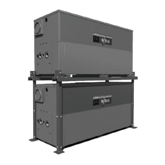
Persons not qualified shall not attempt to install this NOTE: The SureRack is designed to connect to the equipment nor attempt repairs according to these lower unit to provide lateral bracing. Raypak cannot instructions. support using a SureRack as a platform to elevate an upper unit with no lower unit. - Page 5 Figure 1. SURERACK ASSEMBLY...
- Page 6 Item 1* Item 3* Item 2* Item 6* Leg Assembly Leg Assembly Support Beams Cross Members Model X-1 Kit No. Length Length Length Length (in.) (in.) (in.) (in.) 006906 402161 42.79 399-402 006907 402162 49.79 499-502 006908 402163 56.79 074521 37.75 074520 37.75...
-
Page 7: Installation
See Figure 5. Refer to the heater I&O manual for detailed instructions (P/N: 241663 or 241664). These manuals can be found in the document library at www.raypak. Figure 3. ASSEMBLE RACK AROUND BOTTOM com. - Page 8 5. Place one leg (items 1 & 3) at each corner of the 10. Start threading the bolt into the spacer angle. boiler as shown in Figure 1 & Figure 6. The legs are 11. Do not tighten at this step. Leave spacer angle and NOT interchangeable.
- Page 9 X-2 ADD-ON LEG KIT 21. Insert 1½" bolts (item 5) with washers (item 4) (top & bottom) into the cross members. Hand tighten. See NOTE: The X-2 Add-On Leg Kit should be used if it Figure 10. is necessary to meet requirements for above-grade 22.
- Page 10 X-3 RESTRAINT BRACKET KIT NOTE: The X-3 Restraint Bracket Kit can be used stand- alone to securely anchor a single Hi Delta or Delta LTD appliance to structure. Anchor size and quantity determination is site specific, by others P/N for Sizes P/N for Sizes 302-902 992-2342...
- Page 11 UPPER FOOT RESTRAINT INSTALL THE 3/8-16 X 2” SCREW FLAT SIDE OF RESTRAINT AT THIS LOCATION ONLY, ONE FOOT FACES FORWARD ON EACH CORNER OF THE BOILER Refer to Table C and Figure 2 in this instruction for anchoring information. Figure 13.
- Page 12 NOTES Raypak, Inc., 2151 Eastman Avenue, Oxnard, CA 93030 (805) 278-5300 www.raypak.com...
Need help?
Do you have a question about the SureRack Kit and is the answer not in the manual?
Questions and answers