
Related Manuals for Prosilica GC1290C


Summary of Contents for Prosilica GC1290C
- Page 1 USER MANUAL December 3, 2007 GC1290 GC1290C Prosilica Inc. www.prosilica.com tel: 604.875.8855 fax: 604.875.8856 © 2007 Prosilica Inc. All rights reserved.
-
Page 2: Table Of Contents
Supported Features ........................3 Mechanical ..........................4 Connections ..........................5 Cleaning the Sensor........................9 Adjusting the C-mount ......................10 Camera Installation........................11 System Optimization .........................16 Trouble Shooting........................18 Addendum............................19 GC IO Schematic........................20 Isolated Trigger Schematic......................21 Non-isolated Trigger Schematic....................22 Trigger Timing Diagram ......................23 Notes on Triggering........................24 Prosilica Inc. -
Page 3: Introduction
Prosilica provides a 2 year warranty which covers the replacement and repair of all Prosilica parts which are found to be defective in the normal use of this product. Prosilica will not warranty parts which have been damaged through the obvious misuse of this product. -
Page 4: Specifications
Software Interface Standard GigE Vision Standard 1.0 Regulatory Conforms to CE, FCC † Applies to GC1290C only. †† Power consumption will increase with reduced ROI imaging and color interpolation. ††† Nominal operating voltage is 12V. Cameras have been tested at 12V. -
Page 5: Supported Features
1 to 8 pixels Vertical Binning 1 to 16 rows Pixel Formats Mono8, Mono16*, Bayer8, Bayer 16, RGB24, YUV411, YUV422, YUV444, BGR24, RGBA24, BGRA24 Sync Out Modes trigger ready, trigger input, exposing, readout, imaging, strobe, GPO *On monochrome versions only. Prosilica Inc. -
Page 6: Mechanical
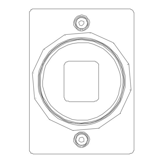
GC1290 User Manual 70-0036A-B Mechanical 4MM DEEP 4 PLCS TYP 12.4* 58.2* 42.5 39.5 45.7 All dimensions are in mm. *Add 0.3mm for color cameras due to the addition of IR blocking filter. Figure 1. GC SERIES mechanical dimensions. Prosilica Inc. -
Page 7: Connections
GC1290 User Manual 70-0036A-B Connections Figure 2. GC SERIES connection diagram. Prosilica Inc. - Page 8 To operate the camera 12V Power with suitable current capacity (see specifications) must be provided on Pin 2 and the Power Ground on Pin 1. A cable assembly providing this power can be ordered from Prosilica (Prosilica P/N 02-8003A for North America or Prosilica P/N 02-8004A for a Universal supply).
- Page 9 These signals are RS-232 compatible. These signals allow communication from the host system via the Ethernet port to a peripheral device connected to the camera. Note that these signals are not isolated and therefore careful attention should be used when designing cabling in noisy environments. Prosilica Inc.
- Page 10 LED COLOR STATUS Solid Orange Ethernet link established. Flashing Orange Ethernet activity. Item 4: Status LED 2 LED COLOR STATUS Solid Green Normal operation. Flashing once per second Boot up pending 3 quick flashes once per Camera fault. second. Prosilica Inc.
-
Page 11: Cleaning The Sensor
Repeat this process until the debris is gone. If this process fails to remove the debris, then contact Prosilica. Prosilica Inc. -
Page 12: Adjusting The C-Mount
Use an adjustable wrench to loosen locking ring. Be careful not to scratch the camera. When the locking ring is loose, unthread the ring a few turns from the camera face. A wrench suitable for this procedure can be provided by Prosilica (P/N 11-0048A). Image to Infinity Use a c-mount compatible lens that allows an infinity focus. -
Page 13: Camera Installation
Camera Installation Computer Interface The Prosilica GC Series cameras will work with any Ethernet network card; however Prosilica strongly recommends using Gigabit Ethernet components that support Jumbo Frames. A Jumbo Frame is loosely defined as a frame size greater than 1500 bytes however typical Jumbo Frames are around 9000 bytes. - Page 14 Connections icon. Double click the relevant network card listed or right-click the relevant network card and select Properties. This will open the properties window for your network card. See Figure 5. Figure 5. Network card main properties window. Prosilica Inc.
- Page 15 255. 255. 0. 0. Click OK to save changes. Note that if Windows reports a conflict with the above IP address, simply repeat the above steps and change the last digit of the IP address to a different value. Figure 6. Network card TCP/IP address. Prosilica Inc.
- Page 16 All Gigabit Ethernet cabling and connectors should be CAT5E or CAT6 compatible. Cable lengths must not exceed 100 meters. Power Connection The camera requires a 12V DC power supply that can source a minimum of 500 mA of current. See the Connections section of this document for more information. Prosilica Inc.
- Page 17 Plug in the Prosilica camera via the Gigabit Ethernet port. Plug in the power connection. Verify that the Status LED 2 is a solid green. Run the Prosilica GigE Viewer Application. It will take a few seconds for the camera to be recognized. If the camera does not appear in the Viewer list after approximately 10 seconds then try disconnecting and reconnecting the power.
-
Page 18: System Optimization
Properties. This will open the properties window for your network card. See Figure 9. Figure 9. Network card main properties window. o From the Properties window select Configure then select the Advanced tab. See Figure 10. Prosilica Inc. - Page 19 From the main properties dialog as in Figure 9, make sure that only the Internet Protocol (TCP/IP) check box is selected then click OK. The card is now optimized for use with the Prosilica camera. o Open the viewer and set the PacketSize to 8228.
-
Page 20: Trouble Shooting
Driver Issues TBD. Camera will not trigger Check cabling and connections. Verify that external trigger circuit is providing a compatible trigger signal. Use the Prosilica Viewer program in trigger mode to eliminate possible software issues. Prosilica Inc. -
Page 21: Addendum
GC1290 User Manual 70-0036A-B Addendum Prosilica Inc. -
Page 22: Gc Io Schematic
MAX3221CPWR FORCEOFF 0.1u 0.1u RS232-TXD DOUT 0.1u FORCEON LOGIC TXD 0.1u INVALID LOGIC RXD ROUT RS232-RXD VDD-3.3 TEXAS INSTRUMENTS SN74LVC2G241DCU LOGIC SY NC OUTPUT 2 SY NC OUTPUT 2 SY NC INPUT 2 LOGIC SY NC INPUT 2 Prosilica Inc. -
Page 23: Isolated Trigger Schematic
This circuit assumes a 10mA drive current (I ) from User’s trigger circuit into camera through R1. R2 is connected to the open collector of Fairchild MOCD207. The corresponding transistor emitter is connected to isolated ground. See the Fairchild MOCD207 datasheet for more detailed information. Prosilica Inc. -
Page 24: Non-Isolated Trigger Schematic
The non-isolated trigger circuit is connected to a Texas Instruments SN74LVC2G241 buffer/driver inside the camera. The required sync input current is less than 10uA and the maximum sync output current is 24mA. See the Texas Instruments SN74LVC2G241 for more detailed information. Prosilica Inc. -
Page 25: Trigger Timing Diagram
GC1290 User Manual 70-0036A-B Trigger Timing Diagram Readout Time Trigger Latency Expose Start Registered Delay Exposure Time User Trigger Logic Trigger Exposure Trigger Jitter Readout Interline Time Trigger Ready Imaging Idle Prosilica Inc. -
Page 26: Notes On Triggering
For applications requiring the shortest possible Trigger Latency and the smallest possible Trigger Jitter the User Trigger signal should be applied when Imaging is false and Idle is true. o In this case, Trigger Latency and Trigger Jitter are as indicated in the Specifications section. Prosilica Inc. - Page 27 User Trigger signal should be applied as soon as a valid Trigger Ready is detected. o In this case, Trigger Latency and Trigger Jitter can be up to 1 line time since Exposure must always begin on an Interline boundary. Prosilica Inc.
Need help?
Do you have a question about the GC1290C and is the answer not in the manual?
Questions and answers