
Summary of Contents for Belief 4W2002 12C21
- Page 1 Air parking heater Technical description, installation, operation and maintenance instructions. Product type Order No. Diesel 4W2002 12C21 Diesel 4W2002 24C21 Air heater for operating independently of the engine. Jan. 25th,2022...
- Page 2 Preface Thank you for choosing 2KW air parking heater. This instruction book describes the structures, working principles, installation and operation of the parking heater. For correct use of the heater, please read this instruction book carefully before installation and use. The instruction book shall be saved in a convenient place for later reference.
- Page 3 1 Introduction The main equipment of Model 2KW parking heater (hereinafter referred to as the heater) is a small fuel furnace controlled by a single-chip micro- processor. Its furnace body (the heat exchanger) is located in the hood-shape case, which serves as independent air passage.
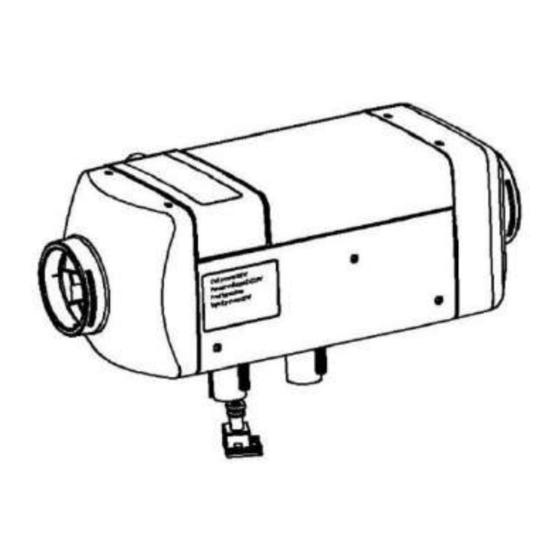
- Page 4 3 Structures and Working Principles The structures of the main heater are shown in Fig. 2 3.1 Heater Fig.3 is the diagram for structure of the heater. Heat exchanger 1 is the combustion furnace body, made of die-casting aluminum, with radiating fins around and at the rear end.
- Page 5 3.2 Hood-Shape Case 1-Junction box cover 2-Top hood-shape cover 3-Hot air outlet 4-Bottom hood-shape cover 5-Air inlet of heater 6-Air inlet/exhaust hood Fig. 4 The structure of the hood-shape case is shown in Fig. 4. It consists of the top cover 2 (The junction box cover 1 can be fixed on 2), bottom cover 4, air inlet hood 6, air inlet of heater 5 and hot air outlet 3.
- Page 6 excessive temperature of heat exchanger, abnormal of power voltage and speed of fan motor when heater operation, the heater will turn off and enter into locked status (not working of glow plug, fuel pump and fan motor, LED light flashing on control switch) for protection.
- Page 7 3.3.4 Circuit Interfaces The following circuit interfaces can be found on the controller case: Socket X1 for fan motor, Socket X2 for glow plug, Socket X3 for overheating sensor, Socket X4 for the leads to fuel pump Socket X6 for the main wire bundle. Fig.5 Please refer to Fig.
- Page 8 3.6 LCD control switch (Optional device, see Fig.7) Display set temperature Set heat starting time Set heat time Display fault information Eliminate fault code Digital display power level Fig.7 3.7 GSM remote controller (Optional device, see Fig.8) GSM remote controller is an extended function device of parking heaters which can be started and stopped through calling or sending message to the number of SIM card in the GSM...
- Page 9 4 Installations Only special-purpose parts can be used for installation of the heater. Fig. 9 is the diagram for installation. The positions and ways of fixing of various parts may vary from one automobile model to another, but the general principles must be followed in conformity with the requirements of this chapter.
- Page 10 goods), special rules must be followed in installing the heater. 4.1.5 Never place fuel tank, compression tank, fire extinguisher, clothes, paper, etc. near the heater or opposite to the hot air vent. 4.2 Installation of the Main Heater 4.2.1The main heater can be installed inside the vehicle or outside the vehicle. But when it is installed outside the vehicle a shield which can be prevent the damage (splash of stones)of external force(supplied by retailers).The heater can’t be soaked in the water or in the rain for a long time(heater should be shut off).The heater should be...
- Page 11 4.2.4 If the sickness of the installation panel<1.5mm a mounting plate may need. Between mounting plate and the car body must also be sealed (use glass glue(Fig.12). Fig 11 Fig 12 Attention: For re-installation of the heater , a new gasket must be used to replace the old one. 4.2.5Direction for installation of the heater is shown in Fig.
- Page 12 shall not be smaller than 60mm. Its material shall be capable to resist temperature of 130℃. 4.3.3 The maximum pressure drop between the air inlet side and air outlet side of the air heating system shall not be greater than 0.15kPa. 4.3.4 The hot air from the heating system shall not erupt onto such parts that are unable to resist heat.
- Page 13 4.4 Installation of Fuel Supply System The fuel supply system for the heater is as shown in Fig. 16. 1-Fuel tank 2-Fuel extractor 3-Fuel pipe connector 4-Filter 5-Fuel pipe 6-Fuel pump 7-Damper 8- Non-return value Fig.16 4.4.1 The fuel pump shall be fixed in automobile with a fuel pump clamp with protective rubber cover.
- Page 14 4.4.4 Installation of Fuel Filter A fuel filter shall be installed before the fuel inlet port. Please make sure that the fuel flow is correctly followed. Its position shall be in conformity with Fig. 18. Fuel filter should be changed after 2 years, fuel pipe joints and clamps should also be changed.
- Page 15 sucking in impurities sediment on the bottom of fuel tank. 4.4.6.2 If fuel is sucked from the fuel pipe to the engine, the fuel pipe from the fuel tank to the fuel filter shall be disconnected and re-connected with the thicker pipes of the reducing T and the thinner pipe of the reducing T shall connect the fuel pump of the heater via oil pipe fitting and fuel pipe.
- Page 17 indicator on the case, so as to identify the working conditions (operation/stop) of the heater easily. The plugs on the leads from the control switch shall be connected to the main wire bundle and make self-locking mechanism. Note to remove the knob firstly, then install the knob after fixing the screw.
- Page 18 4.6.3 Both the air inlet pipe and exhaust pipe shall come outwards and downwards from the heater (Fig. 24), otherwise a Φ4mm hole shall be b) Wrong a) Correct prepared at the bottom of the pipe for Fig.24 discharge of condensation water. If the pipe need curve, the radius cannot be smaller than 50mm.Also, the sum of Direction of running vehicle...
- Page 19 5 Methods of Operation 5.1 The heater control with three ways. (1) Use the control switch(normal configuration). (2) Use LCD control switch(optional choice). (3) Use GSM mobile phone controller(optional choice). 5.2 Use the control switch 5.2.1Power on Push air conditioner ( constant temperature) button or heating(constant power) button, then the indicator light of air conditioner(constant temperature)or heating(constant power) flash 0.3S, then lit, said controller has started work, enter the corresponding working mode.
- Page 20 5.2.5 Use any other way shut off the heater (cut off the power) directly is not allowable. 6 Treatment of Usual Troubles 6.1 During use, the heater may become unable to start normally or die out after start. Such troubles may lead to locking state. In such case, you can press the button which is lighting on then work indicator goes out.
- Page 21 Times of flashes Troubleshooting methods of LED a Check whether the fuel pipe is blocked or whether the fuel in the tank is sufficient. b Check whether the exhaust pipe is blocked. c Check whether fuel mass is appropriate. a Ditto b Ditto c Ditto d Replace the fuel pump a Abnormal voltage, if the voltage is very low, then batter y should be charged.
- Page 22 7 Precautions 7.1 After the heater is installed, in order to remove air trapped in the fuel supply system thoroughly and fill the fuel route with fuel only we Specially designed for oil pump function alone: In the Ventilation mode (fan rotation), press and hold the ventilation key does not release, first press the key on air conditioning, air conditioning light is lit, and then click the warm key, warm light is lit, all three lights lit ,...
- Page 23 At this time, the overheating sensor shall be replaced too. 7.9 The exhaust pipe of the heater for discharge of waste gas after combustion, if arranged in an area with passengers, shall be replaced with qualified one when it has worked for 10 years.
Need help?
Do you have a question about the 4W2002 12C21 and is the answer not in the manual?
Questions and answers