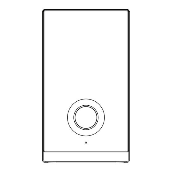
Summary of Contents for LIVINOX WH T Series
- Page 1 OPERATION MANUAL Before operating this appliance, please read these instruction completely. MADE IN MALAYSIA...
-
Page 2: Parts Identification
PARTS IDENTIFICATION 17 17 Note (*) : Pump Model Only (**) : Except for Singapore Model Terminal Block Front Cover Main PCB Board LED Indicators Water Outlet Connection Test & Reset Button TRIAC Pump Knob* Water Inlet Connection Temperature Control Knob Reed Switch Assy Stop Valve Mesh Filter... - Page 3 Provides user the ability to adjust the water temperature precisely based on their own preferences. 2. Built-in Residual Current Device (RCD) In the event of current leakage, Livinox’s highly sensitive built-in RCD will cut o both live and neutral power supply 3. Inverter DC Booster Pump In places where water pressure is inherently low, Livinox’s state of the art DC pump...
-
Page 4: Important Safety Information
IMPORTANT SAFETY INFORMATION WARNING ! Products manufactured by us are safe provided they are installed, used and maintained in good working order in accordance with our instructions and recommendations. Always refer to this manual if you have any doubt. The appliance must be earthed. Improper grounding could cause electric shock. If any of the following conditions occur, immediately switch o the mains and contact the sales agent for repair. - Page 5 HEATER UNIT INSTALLATION DIAGRAM Rubber Rubber Washer Washer Screw Fig.2 1. Select a suitable position in the bathroom. 2. Pull out the Temperature Control Knob and then remove the screw (A) at the ..ibottom of the unit. 3. Remove the Front Cover from the bottom and then lift up the front cover. 4.
- Page 6 SHOWER BRACKET INSTALLATION Fig. 4 1. Mark 2 screw points of the Shower Bracket beside the Instant Hot Shower. It is recommended that the top of the portion is in level with the top of Instant Hot Shower. 2. Use 6mm diameter drill and make the wall plug holes in depth of 34mm. 3.
- Page 7 RAIN SHOWER SET INSTALLATION PROCEDURES 3-WAY DIVERTER VALVE 3-Way Diverter Valve Rainshower Water Outlet Hand Shower Water Outlet Water Inlet 1. Do marking for the location of the lower and upper bracket. 2. Assemble the upper tube with rain shower and lower tube with divider. 3.
- Page 8 PLUMBING PROCEDURE This Electric Instant Water Heater is a single point system and the “Water Outlet” can only be fitted to the PVC Hose and Handshower set provided. NO CONTROL VALVE OR FITTING CAN BE FITTED TO THE WATER OUTLET. 1.
-
Page 9: Electrical Installation
ELECTRICAL INSTALLATION WARNING ! 1. This appliance must be EARTHED. Improper grounding could cause electrical shock. Remember to SWITCH OFF at mains before carrying out any electrical work. Refer to the previous TABLE 1 for the correct cable size. Use double coated exible cable having nominal cross-sectional area between 2.5mm². Lead the power cable from the MCB to a “ON/OFF”... - Page 10 continue from ELECTRICAL INSTALLATION METHOD OF ALIGNMENT WHEN FIXING FRONT COVER Position At O Position At O Front Cover Fig.6b Fig.6a TABLE 1 - ELECTRICAL LOADING TABLE Minimum Conductor Size (csa) Voltage Power Current On/O Fuse / (AC) (kW) Switch (A) MCB (A) mm²...
- Page 11 TEST RUN 1. Turn on the water supply and Stop Valve, the water will ow through the Handshower. Switch on the electrical supply. 3. Turn the Temperature Control Knob to ‘ON’ , the Yellow Indicator light (Power) will turn on, hot water will ow out within a few seconds. The more Temperature Control Knob being turned in clockwise direction, the hotter the shower is.
-
Page 12: Maintenance
MAINTENANCE Read the section ‘IMPORTANT SAFETY INFORMATION’ rst. TEST THE ‘RCD’ REGULARLY (This procedure is highly recommended to test at least once a month) Turn on the electricity and water supply, all LED indicators will light up. If the Temperature Control Knob is in "ON" position, the power LED will light up also. Press the RCD button, the RCD/Earth lamp should turn RED and start blinking. -
Page 13: Wiring Diagram
WIRING DIAGRAM WIRING DIAGRAM - DC PUMP MODEL Double Action Thermostat * Manual-Reset Auto-Reset Relay Power On/Off Pump Speed Control Test Power On/Off Reset Temperature Control Electronic ELCB,15mA Sensitivity On/Off Switch Relay * Manual Reset (90 C Thermostat) For Models rated 4.5kW and below, thermostat is manually resetable. - Page 14 WIRING DIAGRAM WIRING DIAGRAM - NO PUMP DPDT MODEL Double Action Thermostat * Manual-Reset Auto-Reset Relay Test Power On/Off Reset Temperature Control Electronic ELCB,15mA Sensitivity On/Off Switch Relay * Manual Reset (90 C Thermostat) For Models rated 4.5kW and below, thermostat is manually resetable.
- Page 15 WIRING DIAGRAM WIRING DIAGRAM - NO PUMP NO ELCB MODEL Double Action Thermostat Auto-Reset On/Off Switch Power On/Off Temperature Control * Manual Reset (90 C Thermostat) For Models rated 4.5kW and below, thermostat is manually resetable.
-
Page 16: Electrical Specification
ELECTRICAL SPECIFICATION 2.4kW TO 6.0kW 220/230/240Va.c. 50/60Hz 0.1 Bar (10kPa) Min. INLET WATER PRESSURE Max. INLET WATER PRESSURE 6 Bar (0.6MPa) 365 x 204 x 103 (mm) NETT WEIGHT 1.4kg (No Pump) 1.8kg (DC Pump)

Need help?
Do you have a question about the WH T Series and is the answer not in the manual?
Questions and answers