Table of Contents
Advertisement
Quick Links
Advertisement
Table of Contents

Summary of Contents for Corscience CS10803
- Page 1 Combination Sensor Manual CS10803 Seite 1 von 24...
- Page 2 Manufacturer: Corscience GmbH & Co. KG Hartmannstraße 65 91052 Erlangen Germany www.corscience.de Product Name: Combination Sensor Contact Address EU: BEE Medic LLC. Zeppelinstrasse 7 78224 Singen Germany eMail: info@ beemedic.de Website: www.beemedic.de Contact Address non-EU and EMEA: BEE Medic LLC.
-
Page 3: Table Of Contents
Contents OVERVIEW ......................5 INDICATIONS FOR USE ................6 SAFETY NOTICES ..................6 Usage ..............................6 Intended Purpose ..........................7 2.2.1 INTENDED USE ........................7 2.2.2 USER POPULATION ....................... 7 2.2.3 CONTRAINDICATIONS ......................7 2.2.4 TARGET PATIENT POPULATION – MEDICAL CONDITIONS ........7 2.2.5 ENVIRONMENT ........................ - Page 4 PLUG DIAGRAM ..................20 NOTICES ON EMC ACCORDING TO EN 60601-1-2 ....... 21 WARRANTY ..................23 COPYRIGHT NOTICE ................23 DECLARATION OF CONFORMITY ............24 Seite 4 von 24...
-
Page 5: Overview
Overview It can be useful in terms of therapy to measure not only the EEG but also other physiological parameters and to provide feedback based on them. A device that does exactly this is the Combination Sensor. It’s highly functional housing contains three different sensors with measuring amplifiers, which allow for the precise and low-noise measurement of three physiological parameters. -
Page 6: Indications For Use
1 Indications for Use The Combination Sensor is a biofeedback sensor to measure GSR, skin temperature and heart rate. GSR and skin temperature are not measured in absolute values. The purpose is to measure trends. The Combination Sensor may only be used by trained professionals who can ensure safe handling. -
Page 7: Intended Purpose
The meaning of the symbols on the label of the Combination Sensor: Conformity symbol 0482 Please dispose of the product properly, do not put into regular trash. Manufacturer Year of production QR Code Serial number Medical device 2.2 Intended Purpose 2.2.1 INTENDED USE The Combination Sensor is a biofeedback sensor to measure GSR, skin temperature and heart rate. -
Page 8: Environment
2.2.5 ENVIRONMENT The Combination Sensor may be used in professional healthcare facilities, such as physician offices. It is not intended for use in home healthcare environments or in special environments, such as heavy industry or HF surgical environments. 2.2.6 DEVICE DESCRIPTION AND PRINCIPLES OF OPERATION For device description and principles of operation, please see chapter 3. -
Page 9: Device-Related Safety Information
WARNING Entanglement or Strangulation by the cable of the Combination Sensor • The patient and the cable should always be arranged in a way that it is not possible for the patient to become entangled or strangled by the cable. 2.6 Device-related Safety Information WARNING •... - Page 10 WARNING Portable RF communications equipment (including peripherals such as antenna cables and external antennas) should be used no closer than 30 cm (12 inches) to any part of the Combination Sensor, including cables specified by the manufacturer. Otherwise, degradation of the performance of this equipment could result.
-
Page 11: Function
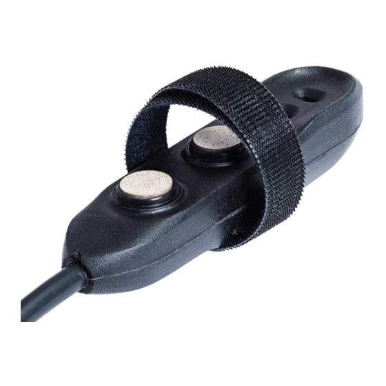
3 Function 3.1 Description Therapist computer Client screen Client feedback ® EEG NeuroAmp Combination Bio-Signals Sensor Figure 1: Usage of the Combination Sensor in a Biofeedback session The Combination Sensor consists of an arrangement of three sensors to measure Galvanic Skin Response, skin temperature and heart rate (see Figure 2). - Page 12 Light source for blood flow Temperature sensor and reflectivity measurements (not visible) Sensors for GSR Optical sensor Figure 2: Detail image of the Combination Sensor with the localization of the three individual sensors. For the sake of clarity, most of the finger strap is cropped. Figure 3: Combination Sensor is attached by the finger strap to the left index finger.
-
Page 13: Electromagnetic Compliance
Figure 4: Connection of the Combination Sensor cable to the rightmost socket on the EEG NeuroAmp®. The Combination Sensor only functions when connected to this specific socket. 3.2 Electromagnetic Compliance The Combination Sensor was tested according to the IEC 60601-1-2 and complies with: •... -
Page 14: Set-Up
4 Set-Up 4.1 Unpacking the Combination Sensor WARNING Death due to suffocation if packing material is swallowed • Store packing material out of reach of children Unpack your Combination Sensor. Please verify that the device is not damaged. If the device is damaged, please return it for a replacement. -
Page 15: Connecting The Combination Sensor To The Digitizing Unit
4.3 Connecting the Combination Sensor to the digitizing unit The Combination Sensor has a Mini-Din8 plug, which plugs directly into the EEG NeuroAmp®. Please make sure to only plug the Combination Sensor into the rightmost socket on the EEG NeuroAmp® (see Figure 4). Interfaces to other digitalization units might be added in the future. -
Page 16: Operation
Operation The Combination Sensor is controlled entirely by the Biofeedback/Neurofeedback software on the computer and powered by the EEG NeuroAmp®. No user interaction with the device is necessary. In order to attach the Combination Sensor to the finger, cut off a 10cm-long piece of the tape that comes with the sensor. -
Page 17: Interpretation Of The Measured Data
5.1 Interpretation of the measured data Figure 7: Display of the sensor data Figure 7 shows the recorded sensor data. The HRV (Heart Rate Variability - first diagram) and the Stress Index (last diagram) are calculated according to established methods described in the literature. -
Page 18: Definition Hrv
5.1.1 Definition HRV HRV is defined as the deviation of the current heart rate from a completely rhythmic sequence. The numerical value displayed as HRV corresponds to the Min / Max interval of the heart rate in a defined time slot. In general, a higher value indicates that the heart is able to change the time between two heartbeats depending on physical or psychological stress and therefore react flexibly to varying challenges. -
Page 19: Cleaning, Maintenance, Storage And Disposal
6 Cleaning, Maintenance, Storage and Disposal Great care was taken to develop and produce this device, and it should be handled with just as much care. If you follow these instructions carefully, you avoid the premature expiry of the warranty and enjoy the safe use of your product for years. 6.1 Cleaning and Maintenance For disinfecting your Combination Sensor we recommend the disinfectant wipes Incidin Wipes Premium. -
Page 20: Technical Data
Technical Data Sensors Number of sensors Skin resistance 0.2 – 100µMho, Umax 2.5V, Imax 2.5µA Heart rate Optical measurement using 940nm and 660nm Temperature range 20°- 40°C or 68°-104°F Measurement rate 62 samples/s Time constant (Temp) 60 s Interface Power Supply 5V / 5mA Plug Mini-Din8, male... -
Page 21: Notices On Emc According To En 60601-1-2
9 Notices on EMC according to EN 60601-1-2 Guidelines and Manufacturer´s Statement – Electromagnetic Emissions The Combination Sensor is intended for use in the electromagnetic environment specified below. The customer or the user of the Combination Sensor should assure that it is used in such an environment. RF emissions CISPR 11 Group 1 RF emissions CISPR 11... - Page 22 IMMUNITY to proximity fields from RF wireless communications equipment Test Band Service Modulation Maximum Distance Immunity frequency (MHz) power Test & Compliance (MHz) Level (V/m) Pulse modulation 380 - 390 Tetra 400 18 Hz GMRS 460, ± 5kHz 430 - 470 FRS 460 deviation 1 kHz sine...
-
Page 23: Warranty
10 Warranty The Combination Sensor is guaranteed to be free from defects in material and workmanship for one year from the date of purchase. In the unlikely event that repair is necessary within the warranty period, call BEE Medic to receive a Return Authorization. -
Page 24: Seite 3 Von
12 Declaration of Conformity Seite 24 von 24...
Need help?
Do you have a question about the CS10803 and is the answer not in the manual?
Questions and answers