Table of Contents
Advertisement
Quick Links
Advertisement
Table of Contents

Summary of Contents for OPTIX WRX600
-
Page 1: Contents
WRX600 SIX MOTOR CORE ALIGNMENT FIBER OPTIC FUSION SPLICER Please read this Operation Manual carefully before operating the equipment. Comply with all safety procedures and warnings in this manual. Keep this manual properly in a safe place. Issued on 2022-9-30... -
Page 2: Table Of Contents
CONTENTS CONTENTS WARNINGS AND CAUTIONS FOR SAFE OPERATION PRODUCT INTRODUCTION 1. STANDARD CONFIGURATION OF OPTICAL FIBER FUSION SPLICER 2. OPTIONAL CONFIGURATION OF OPTICAL FIBER FUSION SPLICER 3. OTHER NECESSARY ACCESSORIES FOR FUSION SPLICING OPERATION 4. DESIGNATION OF COMPONENTS OF OPTICAL FIBER FUSION SPLICER RECOMMENDATIONS AND BEST PRACTICES OF FUSION SPLICING 10-11 BASIC OPERATIONS... -
Page 3: Warnings And Cautions For Safe Operation
WARNINGS AND CAUTIONS The Optical Fiber Fusion Splicer is designed for the optical quartz glass fiber used in the communications, except which it cannot be used to splice any other substances and for other applications. Considering the user’s personal safety, here we provide the user with a lot of safety cautions,because it is possible to result in electric shock, fire and personal injury if the user improperly uses the Optical Fiber Fusion Splicer. - Page 4 WARNINGS AND CAUTIONS Do not use any chemical substances other than alcohol to clean such devices as the objective lens, the V-shaped groove, LCD screen, etc., of the Optical Fiber Fusion Splicer. Otherwise it will cause the imaging to be unclear, with stains, corrosion and damage.
-
Page 5: Product Introduction
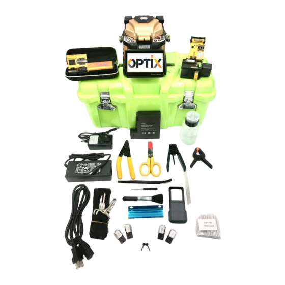
PRODUCT INTRODUCTION 1.STANDARD CONFIGURATION OF OPTICAL FIBER FUSION SPLICER Item WRX600 Core Alignment Splicer WRXCL10 Precision Cleaver with Bin WRXTS6 Thermal Stripper 900um Fiber Holders (pr) 250um Fiber Holders (pr) SOC Holder Battery Spare Electrodes Cooling Tray 10 AC Adapter (Charger) -
Page 6: Designation Of Components Of Optical Fiber Fusion Splicer
PRODUCT INTRODUCTION DESIGNATION OF COMPONENTS OF OPTICAL FIBER FUSION SPLICER... - Page 7 PRODUCT INTRODUCTION...
-
Page 8: Recommendations And Best Practices Of Fusion Splicing
RECOMMENDATIONS AND BEST PRACTICES OF FUSION SPLICING 1. How to Get Small Splicing Loss 1-1.Necessary Regular Cleaning Jobs ● Clean V-Shaped Groove ● Clean Optical Fiber Pressure Head ● Clean Objective Lens In case of cleaning Objective Lens,it is unnecessary to remove needle electrodes 1-2. - Page 9 RECOMMENDATIONS AND BEST PRACTICES OF FUSION SPLICING 2-2. Storage Battery ● Even if the storage battery is not used, its capacity will gradually decay over time, and if it is fully discharged, it may never be able to charge again. So if it will be stored for a long time, or it has been used, please charge it in time.
-
Page 10: Basic Operations
BASIC OPERATIONS 1. POWER CONNECTION OPTICAL FIBER FUSION SPLICER provide two power-supply modes: ① Storage Battery; ② AC Adapter. Please make sure that OPTICAL FIBER FUSION SPLICER shall be turned off in case of operating it. 1-1.Insertion of the Storage Battery. Insert the storage battery into the battery slot until it is properly in place. - Page 11 BASIC OPERATIONS...
-
Page 12: Maintenance Of Fusion Splicing Quality
MAINTENANCE OF FUSION SPLICING QUALITY 1. CLEANING AND CHECKING BEFORE FUSION SPLICING The following describes the maintenance checks for the key cleaning points and the important parts. 1-1.Cleaning the V-Shaped Groove If there is dust or contamination in the V-shaped groove, the Optical Fiber Pressure Head can not suppress the optical fiber correctly, resulting in high fusion splicing loss. - Page 13 MAINTENANCE OF FUSION SPLICING QUALITY ● It is recommended to clean the lens before replacing the needle electrode. 2-2. Replacing the Electrode The electrode will wear in use, and the electrode tip will be aggregated with silicon oxide, so regularly cleaning the oxide can effectively extend the life of the needle electrode.
- Page 14 MENU How to Enter and Select Menu Once the system is “ready”, press“ENTER”to enter the menu, and press the cursor controls to select Menu Main Menu includes the following six applications: Common Function, Parameter Set, System Debug Machine Info, Splice Options, Quick Check...
- Page 15 MENU 1. Menu: Common Function 1-1. Arc Calibration In order to ensure the stable fusion-splicing quality, the user should operate regularly. It is necessary to do arc test when using the Optical Fiber Fusion Splicer under the following conditions: ultra-high temperature, ultra-low temperature, very dry, very wet, electrodes degradation, fusion splicing of the heterogeneous optical fibers, cleanness, or after replacing the electrode.
- Page 16 MENU After arc, a numeric value will be displayed on the screen. If the value is within the range of 45-65, it means that the arc power is OK. If the value is less than 45, it means that the arc power is weak, if more than 65, arc power is too strong After arc, if shown weak or strong, please press , store the record , and then do an arc test again until shown...
- Page 17 MENU 1-4. Arc Force It is off when splicing normally. When turned on, the fusion splicer will splice fiber even if it is not proper to splice. 1-5. Aligning Mode - Accurate or Quick...
- Page 18 MENU 1-6. User Password Setting - To set a user password 1-7. Aligning Mode - Accurate or Quick 1-8. Cleave Arc - Over Splices the fiber with strong arc...
- Page 19 MENU 2. Menu: Parameter Set 2-1. Splice Program - Select splice program according to type of fiber or Smart to allow fusion splicer to auto detect fiber type...
- Page 20 MENU 2-2. Arc Parameter - Press to change the detailed Parameters (DEFAULT is Factory settings, cannot be changed). Not recommended except by authorized staff. Function Items Function Instructions Range PreArc time PreArc time 0-1.0 PreArc Power PreArc Power 0-250 Arc Time Splice Arc time 0-10.0 Arc Power...
- Page 21 MENU The gad when the left and right fiber finished alignment 0-50 2-3. Heat Mode - Auto or Manual AUTO mode - Place the fiber protective sleeve in the heating box, close the heating box cover and it will heat automatically MANUAL mode - Place the fiber protective sleeve in the heating box, close the heating box cover, press to start heating...
- Page 22 MENU 2-6 HEAT PARAMETER - Adjust heat time and heat temperature for each Heat program, and utilize "Sustained Heat" function Sustained Heat - Oven will stay on for four minutes in order to heat faster...
- Page 23 MENU Function Function Instructions Range Heat time Heating box working time 10-90 Sustained heat (4 mins) Sustained heat (4 mins) Turn off/turn off Heat Temperature Heat Temperature 100-250 Calibration value Sensor Calibration value Sensor Calibration Using to correct the temperature sensor deviation 2-7.
- Page 24 MENU 3. Menu “System Debug” 3-1. Sensor Status Check the status of each Sensor.
- Page 25 MENU 3-2. Stabilize Electrodes Sometimes when the outside environment changes, the Arc power will be unstable. That leads to a big splicing loss. Especially when the fusion splicer is located in a low altitude area to high altitude area, so it needs some time to stabilize Arc power.
- Page 26 MENU 3-4. Display Config-Manual According to general splicing steps to strip, cut and place optical fiber. The screen will show the following: Place fiber and press Enter. Press after placing the optical fiber. “◀”and“▶”are movements about the left and right position of optical fiber. “▲”and“▼”are movements about the up and down position of optical fiber.
- Page 27 MENU 3-5. Display Config-CCD This is a camera focus calibration. Press , and enter in the menu of “Display Config-CCD” The display will show: Press “Auto” to Self Check. After place the optical fiber and press the button 3-6. Display Config – LED Press , select “Display Config -LED”, press to adjust lightness of X-axis,...
- Page 28 MENU 3-7. Display Setting – Dust Check Check whether there is dust in the display system Press , enter Display Config – Dust Check Menu, check whether the screen shows Dust Check Success. 3-8. Motor Move Test or “Push” Test Press , enter “Motor Forward Test”,screen will show“...
- Page 29 MENU 3-9. Motor Alignment Test Press , enter Motor Alignment Test, screen will show “UP to test X-axis motor, Down to test Y-axis motor” 3-10. Motor Manual Test Prees , enter Motor Manual Test,press to select the motor Left Moto Manual Trigger Press , select L Moto Manual Trigger, fix a cleaved fiber on the left fixture, make the fiber view in the screen, press and hold...
- Page 30 MENU press to move the fiber automatically, press again to stop moving, X-axis Moto Auto Trigger Press , select X Moto Auto Trigger, fix a cleaved fiber on the left fixture, make the fiber view in the screen, press to move the fiber automatically, press again to stop moving. Y-axis Moto Auto Trigger Press , select Y Moto Auto Trigger, fix a cleaved fiber on the right fixture, make the fiber view in the screen,...
- Page 31 MENU 4. Menu: Machine Info You can check the machine serial number, software version number, firmware version number and arc count from this menu. 4-1. Machine SN Machine serial number 4-2. Software Version Machine software version number 4-3. Firmware Version Machine firmware version number 4-4.
- Page 32 MENU 5. Menu: Splice Options 5-1. Pause Stop splice process after alignment creating an aligning pause. Splice will follow through on splice after manually pressing arc button 5-2. Stretch Test or Pull Test Turn Stretch Test ON/OFF. Test the fiber splice with 2.2N of force. 5-3.
- Page 33 MENU 5-6. Auto Focus - Turn on for SMART DETECT and “accurate” aligning 5-7. Time Set 5-8 Function Setting Power Save Switch - machine shuts down automatically after set time Stand-by Time - Set time for machine shut down Image Cache Switch - ON/OFF to save splice images View Cache Image - View splice images Touch Screen Switch - Turn ON/OFF touch screen...
- Page 34 MENU 6. Menu: Quick Check 6-1. Quick Optimize Machine will test parameters including arc power, camera focus, motor alignment, and electrode stabilization . 6.2. Replace Electrode - renews arc count when replacing electrodes 6-3. Residual arc count - Counts the number of arcs for the electrodes.
-
Page 35: Questions And Troubleshooting
QUESTIONS AND TROUBLESHOOTING 1. TURNING ON POWER OF OPTICAL FIBER FUSION SPLICER AND POWER SUPPLY ● Turn ON the power switch, but the power supply does not respond. Reason: a. Power outlet is not plugged in. b. The contact of the power switch is bad. c. - Page 36 QUESTIONS AND TROUBLESHOOTING and finally there will be shown " Lay Optical Fiber Again" . Reason: a. The length of the cleaved optical fiber is unable to meet the requirements. b. There is an obstacle for the press board of the optical fiber to move forward. Solution: The length of the cleaved optical fiber should be a minimum of 10mm.
- Page 37 QUESTIONS AND TROUBLESHOOTING a. There is a failure in the detection system or there is dust on the objective lens. b. In the parameters, the value of “End-Face Setup” of the optical fiber is set too high. c. After the operations of the electrode discharge and the fusion splicing, the windproof cover is opened before the equipment has completed its detection.
-
Page 38: Heating Operations
QUESTIONS AND TROUBLESHOOTING contact your dealer to repair/maintain it or send it back to the factory for repair/maintenance. 3. HEATING OPERATION ● The optical fiber heat-shrinkable sleeve has not completely shrinked. Reason: a. The set heating time is too short. b. -
Page 39: Guarantee And Contact
GUARANTEE AND CONTACT 1. GUARANTEE 1-1.Warranty Period and Conditions If there occurs a failure in the optical fiber fusion splicer within three years starting from the date of goods delivery, we will provide a free repair/maintenance. However, we will not provide a free repair/maintenance within the Warranty Period, if there occur the following events: (1) Failure or damage caused by natural disasters;... -
Page 40: Contact
GUARANTEE AND CONTACT 2. CONTACT Please contact the manufacturer if the user needs support or services at sales@optixamerica.com located in North Babylon, NY Note: If the program has been updated and the structure has been changed, resulting in errors and the unconformity to the manual, please take the actual product as the reference standard. - Page 41 Quick Reference Guide The guide is for the basic operation. For the detailed information, please refer to the Instruction manual. 1、 Power Supply Two ways of supplying power to the fusion splicer : 1.internal battery;2. AC power supply. Please make sure that your fusion splicer is turned off before power is supplied.
Need help?
Do you have a question about the WRX600 and is the answer not in the manual?
Questions and answers