Table of Contents
Advertisement
Quick Links
INSTRUCTION AND MAINTENANCE MANUAL:
FS Shear Blender (FPX-style seal, before 8/2005)
(for pumps with motors frame sizes 140TC thru 320TC)
Архангельск
(8182)63-90-72
Ижевск
Астана
(7172)727-132
Иркутск
Астрахань
(8512)99-46-04
Казань
Барнаул
(3852)73-04-60
Калининград
Белгород
(4722)40-23-64
Калуга
Брянск
(4832)59-03-52
Кемерово
Владивосток
(423)249-28-31
Киров
Волгоград
(844)278-03-48
Краснодар
Красноярск
Вологда
(8172)26-41-59
Курск
Воронеж
(473)204-51-73
Липецк
Екатеринбург
(343)384-55-89
Киргизия
Иваново
(4932)77-34-06
(3412)26-03-58
Магнитогорск
(395)279-98-46
Москва
(843)206-01-48
Мурманск
(4012)72-03-81
Набережные Челны
(4842)92-23-67
Нижний Новгород
(3842)65-04-62
Новокузнецк
(8332)68-02-04
Новосибирск
(861)203-40-90
Омск
(3812)21-46-40
(391)204-63-61
Орел
(4862)44-53-42
(4712)77-13-04
Оренбург
(4742)52-20-81
Пенза
(8412)22-31-16
(996)312-96-26-47
Казахстан
https://fristam.nt-rt.ru/ || fmg@nt-rt.ru
(3519)55-03-13
Пермь
(495)268-04-70
Ростов-на-Дону
(8152)59-64-93
Рязань
(8552)20-53-41
Самара
(831)429-08-12
Санкт-Петербург
(3843)20-46-81
Саратов
(383)227-86-73
Севастополь
Симферополь
Смоленск
(3532)37-68-04
Сочи
Ставрополь
(772)734-952-31
Таджикистан
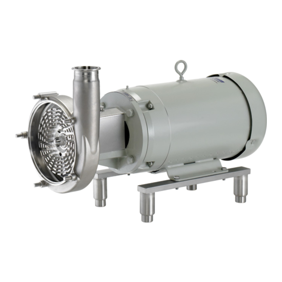
FS Series Pump
(342)205-81-47
Сургут
(863)308-18-15
Тверь
(4912)46-61-64
Томск
(846)206-03-16
Тула
(812)309-46-40
Тюмень
(845)249-38-78
Ульяновск
(8692)22-31-93
Уфа
(3652)67-13-56
Хабаровск
(4812)29-41-54
Челябинск
(862)225-72-31
Череповец
(8652)20-65-13
Ярославль
(992)427-82-92-69
1
(3462)77-98-35
(4822)63-31-35
(3822)98-41-53
(4872)74-02-29
(3452)66-21-18
(8422)24-23-59
(347)229-48-12
(4212)92-98-04
(351)202-03-61
(8202)49-02-64
(4852)69-52-93
Advertisement
Table of Contents

Related Manuals for Fristam Pumps FS Series

Summary of Contents for Fristam Pumps FS Series
- Page 1 FS Series Pump INSTRUCTION AND MAINTENANCE MANUAL: FS Shear Blender (FPX-style seal, before 8/2005) (for pumps with motors frame sizes 140TC thru 320TC) Архангельск (8182)63-90-72 Ижевск (3412)26-03-58 Магнитогорск (3519)55-03-13 Пермь (342)205-81-47 Сургут (3462)77-98-35 Астана (7172)727-132 Иркутск (395)279-98-46 Москва (495)268-04-70 Ростов-на-Дону...
- Page 2 Fristam Pumps ESCRIPTION This manual contains installation, operation, assembly, disassembly and repair instructions for the Fristam FS style pump. The FS style pump is fl ange mounted on a heavy duty cast fl ange support. This fl ange support provides an extremely sturdy method of coupling the pump head and the motor.
-
Page 3: Table Of Contents
FS Series Pump ABLE OF ONTENTS ........................4 ECHNICAL NFORMATION ..................5 ECOMMENDED REVENTIVE AINTENANCE ........................6-13 EPLACEMENT ....................6-7 ISASSEMBLY ........7 DDITIONAL ISASSEMBLY FOR OUBLE ECHANICAL EALS ....................7-9 SSEMBLY .................... 10 HEAR INGLE SSEMBLY RAWING ..............11... -
Page 4: Technical Information
Fristam Pumps ECHNICAL NFORMATION PECIFICATIONS Maximum Inlet Pressure ........................150 PSI Temperature Range ........................-40°F - 400°F ATERIALS OF ONSTRUCTION Primary Product Contact Components ..................AISI 316L Cover Gasket ........................BUNA (standard) Also available in ...........Viton, EPDM, Silicone, Chemraz, Kalrez Surface Finish for Product Contact Surfaces ..............32 Ra (standard) -
Page 5: Ecommended Reventive
FS Series Pump ecommended Reventive aintenance ecommended aintenance Visually inspect mechanical seal daily for leakage. Replace mechanical seal annually under normal duty. Replace mechanical seal as often as required under heavy duty. laStomeR nSPection Inspect all elastomers when performing pump maintenance. We recommend replacing elastomers (o- rings and gaskets) during seal, pump shaft and/or motor replacement. -
Page 6: Seal Replacement
Fristam Pumps EPLACEMENT Begin all pump maintenance by disconnecting the energy source to the pump. Observe all lock out/tag out procedures as outlines by ANSI Z244.1-1982 and OSHA 1910.147 to prevent accidental start-up and injury. OOLS FOR EPLACEMENT 15/16” socket Two 3/4”... -
Page 7: Additional
FS Series Pump the shaft (Figure 9). Discard the seal components after you remove them. l) Loosen the housing clamping bolt (4) with the two 3/4” wrenches until it is loose in the fl ange support (2). (Note: the Figure 9 clamping bolt does not have to be removed.) Now slide the... - Page 8 Fristam Pumps b) Place the fl at gasket (16) into the hub of the housingr. Make sure that it is all the way to the Figure 12 bottom and is seated evenly. c) Install the stationary seal into the housing hub with the smaller face entering the hub fi...
- Page 9 FS Series Pump o) Compress the spring assembly with two fi ngers and install the shaft key (8) into the keyway on the pump shaft (Figure 14). Figure 14 p) Slide the rotor (38) onto the pump shaft (6). The slot in the rotor hub will slide over the rotor key (8).
-
Page 10: Rawing
Fristam Pumps Figure 16: Single Seal Assembly 31 18 27 11 DESCRIPTION ROTOR NUT GASKET ROTATING SEAL O-RING ROTATING SEAL OUTSIDE SEAL DRIVER O-RING FRONT SEAL DRIVER FLAT GASKET INSIDE SEAL DRIVER O-RING STATIONARY SEAL STATIONARY SEAL O-RING SEAL SPRING... -
Page 11: Tationary Seal Assembly
FS Series Pump Figure 17: Single Silicon Carbide Stationary Seal Assembly 31 18 27 11 29 DESCRIPTION ROTATING SEAL O-RING ROTOR NUT GASKET OUTSIDE SEAL DRIVER O-RING ROTATING SEAL FLAT GASKET FRONT SEAL DRIVER INSIDE SEAL DRIVER O-RING STATIONARY SEAL - FRONT HALF... -
Page 12: Rawing
Fristam Pumps Figure 18: Double Seal Assembly 31 18 27 11 11 27 DESCRIPTION FRONT ROTATING SEAL ROTOR NUT GASKET FLAT GASKET OUTSIDE SEAL DRIVER O-RING STATIONARY SEAL FRONT SEAL DRIVER STATIONARY SEAL O-RING INSIDE SEAL DRIVER O-RING REAR ROTATING SEAL FRONT SEAL SPRING REAR SEAL DRIVER &... -
Page 13: Tationary Seal Assembly
FS Series Pump Figure 19: Double Silicon Carbide Stationary Seal Assembly 21 33 27 11 29 DESCRIPTION ROTOR NUT GASKET FRONT ROTATING SEAL OUTSIDE SEAL DRIVER O-RING FLAT GASKET STATIONARY SEAL - FRONT HALF FRONT SEAL DRIVER INSIDE SEAL DRIVER O-RING... -
Page 14: Pump Shaft And / Or Motor R Pump Disassembly
Fristam Pumps UMP SHAFT AND OTOR EPLACEMENT Begin all pump maintenance by disconnecting the energy source to the pump. Observe all lock out/tag out procedures as outlined by ANSI Z244.1-1982 and OSHA 1910.147 to prevent accidental start-up and injury. OOLS FOR... -
Page 15: Pump Assembly
FS Series Pump SSEMBLY If you have replaced the motor, clean off the motor face of the fl ange support (2). Place the fl ange sup- port onto the new motor and replace the motor bolts (26) and lock Figure 22 washers (25). -
Page 16: Fs Series Exploded View
Fristam Pumps COMPONENTS MOTOR FRAME SIZES FOR DOUBLE SEAL 143-256TC ONLY ONLY 25: FS A IGURE SSEMBLY Motor Rotor Nut Gasket Flange Support Rotor Nut Clamping Bolt Nut Pump Cover Clamping Bolt Cover Nuts Pump Shaft Lock Washer Shaft Key... - Page 17 FS Series Pump COMPONENTS FOR DOUBLE SEAL ONLY 1265000132 9/23/03 Rotor Stator Studs Acorn nuts Washer Housing bolt Inner stator o-ring Outer stator o-ring R4: 3/05...
-
Page 18: Installation
Fristam Pumps NSTALLATION NPACKING Check the contents and all wrapping when unpacking the pump. Inspect the pump carefully for any dam- age that may have occurred during shipping. Immediately report any damage to the carrier. Remove the shaft guard and rotate the pump shaft by hand to make sure the rotor rotates freely. Keep the protective caps over the pump inlet and outlet in place until you are ready to install the pump. -
Page 19: Electrical Installation
FS Series Pump shock which can cause severe damage to the pump and system. • Avoid elbows in the suction line if possible. When necessary they should be located 5 pipe diam- eters away from the pump inlet, and have a bend radius greater than 2 pipe diameters (Figure 5). -
Page 20: Nstallation Of
Fristam Pumps NSTALLATION OF ATER LUSH FOR OUBLE ECHANICAL Set up the water fl ush for the double mechanical seal as shown (Figure 6). Use only between 1-2 gal- lons per hour of water at a maximum pressure of 5 PSI. Excessive fl ow of water through the seal increases the pressure inside the seal. -
Page 21: Troubleshooting
FS Series Pump ROUBLESHOOTING Fristam pumps are relatively maintenance free, however, in the event that a problem does arise, the troubleshooting chart below should help you with most of your pump related problems. If a motor problem arises please contact your local motor repair representative. -
Page 22: Echanical
17. Total head of system higher than design head diameter pipe, use larger diameter rotor, of pump check application with Fristam Pumps. 18. Install throttling valve in line, use smaller diameter pipe, use smaller diameter rotor, 18. Total head of system lower than pump design check with Fristam Pumps. - Page 23 FS Series Pump such operation 23. Remove pump cover and clear foreign matter 23. Foreign matter in rotor 24. Provide fi rmer foundation for the pump 25. Replace shaft 24. Foundations not rigid 26. Re-establish gap of the rotor, replace rotor 25.
Need help?
Do you have a question about the FS Series and is the answer not in the manual?
Questions and answers