Table of Contents
Advertisement
Quick Links
REVISED APRIL 2020
Ares F7
FPV RACE FLIGHT CONTROLLER
Quick Reference Manual
Features
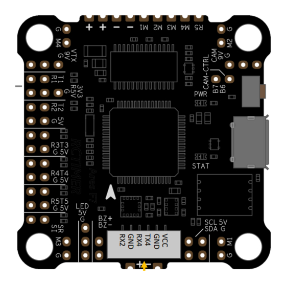
▸ STM32F722 Cotex-M7 MCU 216MHz with 512KB Flash
▸ ICM20602 6-axis Gyro & Accelerometer
▸ BMP280 Barometer
▸ SLC NAND SPI FLASH 128MB
▸ Built-in OSD
▸ Full dc-dc power rails 3.3V/0.5A, 5V/2A and 9V/1.5A
▸ Core 5V & USB power rails with advanced power mux function
▸ 9V power on/off can be controlled by transmitter
▸ Exclusive connector for Ares 60A 4IN1 ESC and DJI FPV Air Unit Module
▸ 4 default ESC signal channels and up to 6
▸ 5 UART serial ports
▸ Cam control rc filter circuit compatible with most cameras
▸ Dimensions 37x37mm and mounting hole 30.5x30.5mm
▸ Voltage 3~4S (DJI air module used) or 3~8S
1
Copyright @ 2020, RCTIMER
Advertisement
Table of Contents

Summary of Contents for RCTimer Ares F7
- Page 1 ▸ 4 default ESC signal channels and up to 6 ▸ 5 UART serial ports ▸ Cam control rc filter circuit compatible with most cameras ▸ Dimensions 37x37mm and mounting hole 30.5x30.5mm ▸ Voltage 3~4S (DJI air module used) or 3~8S Copyright @ 2020, RCTIMER...
- Page 2 Please follow the diagram on this page to connect the desired type of receiver. ◆ Smart Port S.BUS DSM/IBUS DSM 3.3V 3V3/R5V S.BUS CRSF IBUS 5V FPort/S.Port FPORT Air Module Exclusive cable in package RX1 TX1 GND R5V 3V3 TOP VIEW Copyright @ 2020, RCTIMER...
- Page 3 The 9V remains ON in the initial state, it can be controlled ON/OFF by a PINIO function through the user1 ◆ mode switch. VTX CTRL TX2/3/4/5 VIDEO VIDEO Smart Audio IRC Tramp CAM 9V GND GND 9V TVX TOP VIEW Copyright @ 2020, RCTIMER...
- Page 4 In this case, It is not necessary to use the rear half-hole pads to supply power. The telemetry output wire is connected to the RX5 by default. ◆ You can also solder wires to the 9 half-hole pads in their front, but this is not necessary. ◆ BOTTOM VIEW Copyright @ 2020, RCTIMER...
- Page 5 A 10p single plug cable included in the package use to connect 4IN1 ESC to the white connector on the back of ◇ FC in front. Refer to the previous page for connector location. TOP VIEW Copyright @ 2020, RCTIMER...
- Page 6 The IN pad of the LED strips needs to be connected to the LED output pad of the FC. ◆ Use a 5V active buzzer to connect to the BZ + and BZ- pads and be careful not to reverse them. ◆ BZ + means output 5V voltage. COMPASS TOP VIEW Copyright @ 2020, RCTIMER...
- Page 7 The current sensor that needs to be used must first know its output ratio and the signal wire is connected to ◆ the SI pad. The default ratio of Ares F7 is 366. Ares F7 is powered directly by the battery so it does not have a signal input pad. The onboard voltage divider is ◆ configured to 110.
- Page 8 Wiring Diagram ▸ Power supply Ares F7 supports 8 ~ 40V direct input voltage, due to the limitation of DJI Air module and the stability of BEC ◆ output voltage, 3 ~ 4 cells is usually recommended. Ares F7 has 3 pairs of power and ground pads onboard, In the case of using Ares 4IN1 ESC in combination, the ◆...
Need help?
Do you have a question about the Ares F7 and is the answer not in the manual?
Questions and answers