
Related Manuals for Anilam Wizard 211

Summary of Contents for Anilam Wizard 211
- Page 1 Wizard 211 Digital Readout Operations Manual WIZARD 211 INCH INCR SALES & SERVICE: A Tech Authority, Inc. 13745 Stockton Ave. Chino CA 91710 909-614-4522 sales@atechauthority.com P/N 70000421B...
- Page 2 Warranty ANILAM warrants its products to be free from defects in material and workmanship for three (3) years from date of installation. At our option, we will repair or replace any defective product upon prepaid return to our factory. This warranty applies to all products when used in a normal industrial environment.
-
Page 3: Table Of Contents
Contents Contents ..........................iii Introducing the Wizard......................1 The ANILAM Wizard 211 Keypad and Display Windows ..........2 The ANILAM Wizard 211 Back Panel................3 First-Time User Checklist .......................5 About This Manual........................7 Function Code List........................8 Beeper ............................9 Keyboard Entry Error ......................10 Presetting a Dimension ......................11 Resetting an Axis to Zero .....................12... -
Page 4: Contents
Contents (Continued) Axis Reset Only – F 16 ......................33 Parameter Settings – F 20....................34 Metric linear encoders .....................35 Inch Linear Encoders (BT or JB Linear Encoders)..........40 Beeper OFF/ON – F 21 ......................41 Display Dim OFF/ON – F 22/F 23 ..................42 Axis Designation –... -
Page 5: Introducing The Wizard
Introducing the Wizard Thank you for purchasing the ANILAM Wizard 211 Digital Readout (DRO). Review these pages carefully to learn how to properly operate your new DRO. The new DRO offers many features and capabilities never before used in conventional DRO systems. -
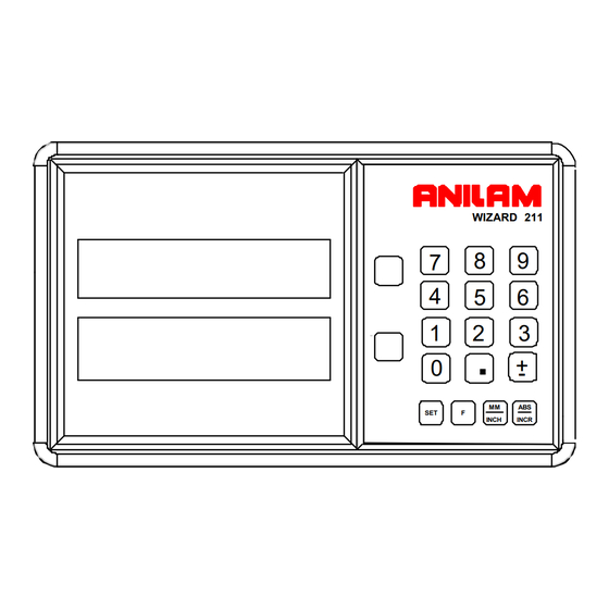
Page 6: The Anilam Wizard 211 Keypad And Display Windows
Introducing the Wizard (Continued) The ANILAM Wizard 211 Keypad and Display Windows NOTE: The Wizard 211 DRO is available in one-axis, two-axis, and three-axis models. For simplicity, the procedures in this manual describe only a two-axis model. Numeric Keys WIZARD 211... -
Page 7: The Anilam Wizard 211 Back Panel
Introducing the Wizard (Continued) The ANILAM Wizard 211 Back Panel Fuse Cover Slot Linear Encoder Connections ON/OFF Switch Power Cord Connection Ground Connection Selecting the Operating Voltage To select the operating voltage for the DRO: 1. Locate the ON/OFF switch on the back panel of the DRO and verify that the switch is in the OFF (0) position. - Page 8 Introducing the Wizard (Continued) Your Wizard’s display was designed to be easy to read: Axis Indicator Indicates Z ABS RST MM INCH Coarse Resolution Diameter Mode Absolute Mode Reset Only Axis Correction Factor Reference Indicator MM or INCH Mode Edge Sensor Approaching Zero Indicator...
-
Page 9: First-Time User Checklist
First-Time User Checklist Your new DRO has many preset values. Before you proceed, please review the following list to verify default settings. If you need to change any setting(s), refer to Parameter Settings – F Description of Setting Factory Setting Your Setting 1. - Page 10 First-Time User Checklist (Continued) For your safety, and to prevent damage to the machine, please verify the following: DRO arm and DRO are securely Yes/No mounted to the machine. 10. The DRO Input-voltage switch Yes/No on the power-entry module (back panel) is set to the correct input voltage.
-
Page 11: About This Manual
About This Manual This manual contains limited text and enlarged graphics for easy use. Actual keystrokes are represented by graphics. The format is as follows: Function Heading Function Description Example with Keystrokes Explanation of Procedures and Observations NOTE: Indicates you must use caution. -
Page 12: Function Code List
Function Code List You can access most DRO features using function codes. Function codes are codes entered by pressing the Function key (F) and then pressing the two-digit code for the feature. The following table lists the function codes available with your DRO. Code Description Page... -
Page 13: Beeper
Beeper The beeper is a standard feature on all ANILAM DROs. Use the beeper to acknowledge a keystroke. For correct keystrokes, a short tone sounds. For incorrect keystrokes, a long tone sounds. The beeper default, preset by ANILAM, is ON. -
Page 14: Keyboard Entry Error
Keyboard Entry Error If you enter an incorrect value, press the axis key again to clear the axis display. If you enter too many numbers on an axis, the DRO display reverts to zero on that axis. When this happens, enter the correct number again. -
Page 15: Presetting A Dimension
Presetting a Dimension Presetting allows you to enter a dimension into an axis display. After you have preset the dimension, you can move the machine until the axis zeros. You can also use the preset feature as a one-line recall mode if the display is set in Incremental Mode. -
Page 16: Resetting An Axis To Zero
Resetting an Axis to Zero When you reset an axis, the display for that axis reverts to zero Use the reset feature when establishing part zero (datum) or clearing the axis at each part location (making incremental moves). To reset one axis (X or Y): 1. -
Page 17: Recalling A Preset Dimension
Recalling a Preset Dimension This feature allows you to recall a preset dimension to the axis display. Use this feature when making multiple moves of the same dimension. NOTE: This feature works only in Incremental Mode. To recall a preset dimension: INCR 1. -
Page 18: Clearing A Preset Dimension
Clearing A Preset Dimension When you clear a dimension, you automatically zero the previously entered dimension in an axis. To clear preset dimensions, one axis at a time: 1. Press the desired axis key to select the axis. 2. Press To clear entered dimensions for all axes: 1. -
Page 19: Centering The Workpiece
Centering the Workpiece This feature allows you to quickly locate the centerline of the workpiece on each axis. Example: To locate the centerline of the workpiece on an axis: 1. Zero the display at one edge of the workpiece. 2. Move to the opposite edge of the workpiece and touch the other edge. 3. -
Page 20: Adding/Subtracting Values
Adding/Subtracting Values This feature allows you to add or subtract values using the axis display values. You can add/subtract a value to/from a value displayed for a machine position or for values you enter in an axis display. Example 1: The axis display indicates 3.425 inches (87 mm). To add 1.259 inches (32 mm) to this value: 1. -
Page 21: Dividing An Axis Value By 2
Dividing an Axis Value by 2 This feature allows you to divide a value on an axis display by 2. You can also divide any values entered in an axis display by 2. Example 1: The axis display indicates 7.126 inches (181 mm). To divide this value by 2: 1. -
Page 22: Inch/Metric Conversion
Inch/Metric Conversion This feature allows you to convert inch values to metric values and vice-versa on all axes. Example: Change 1.000 inch to its metric (mm) equivalent. 1. Press the desired axis key to select the axis. 2. Press The DRO displays the following: i.0000 INCH INCH... -
Page 23: Plus/Minus Key
Plus/Minus (±) Key The ± key allows you to: Change the sign of a preset value. Change the direction of travel on a linear encoder while in parameter setting. Add and subtract values. WIZARD 211 Plus/Minus Key INCH INCR... -
Page 24: Absolute/Incremental (Abs/Incr) Key
Example: If a series of six 2.00 inch (50.8 mm) incremental moves are made, change to ABS Mode to display the total distance moved, which is 12.000 inches (304.80 mm). WIZARD 211 Absolute/Incremental INCH INCR... -
Page 25: Absolute/Incremental
Absolute/Incremental To get the most out of your DRO, you must understand the two types of dimensions most commonly used in blueprints: Absolute (ABS) and Incremental (INCR). Absolute dimensions are measured from a common reference point. In Illustration A, below, the common reference or zero reference point is located on the lower left side of the part. -
Page 26: Absolute Zero Set - F 01
Absolute Zero Set – F 01 F 01 allows you to establish a part zero. The DRO clears all axes counters, both absolute and incremental, to zero. This is similar to Power ON Mode. NOTE: This feature does not clear a dimension entered in Incremental Mode. To clear a dimension entered in Incremental Mode, refer to Recalling a Preset Dimension. - Page 27 EverTrack Mode – F 02 F 02 allows you to recall any position that has been previously stored in Absolute Mode, even in case of power outage. In EverTrack Mode, the DRO can access absolute references along the linear encoder. As a result, EverTrack Mode eliminates the need for a machine home position and a battery backup system.
-
Page 28: Evertrack Tm Mode - F 02
EverTrack Mode – F 02 (Continued) 7. Press This will be the absolute part zero for the selected axis. NOTE: You can also preset a dimension as long as the DRO is in Absolute Mode. The zero position corresponding to the stored preset dimension will be stored and can be recalled using EverTrack Mode. - Page 29 EverTrack Mode – F 02 (Continued) 4. Move each machine axis to the part zero position. 5. Press This will be the absolute part zero position. NOTE: You can also preset dimensions as long as the DRO is in Absolute Mode. The zero position corresponding to the stored preset dimensions will be stored and can be recalled using EverTrack Mode.
- Page 30 EverTrack – F 02 (Continued) All Axes 1. Press to select the feature. Press to select all axes. The axis displays reset to zero and the RIs begin to blink for each axis. CAUTION: During the following step, do not change the machine axis travel direction.
-
Page 31: Setting A Correction Factor - F 03
Setting a Correction Factor – F 03 F 03 allows you to compensate for nominal linear inaccuracies due to your machine or for adding material shrinkage/expansion, as in mold work. The maximum allowable settings are ± 40%. Example: Consider a 1.325-inch (33.655 mm) travel on the display that is only 1.320-inch (33.528 mm) actual distance moved on the axis. -
Page 32: Correction Factor Off/On - F 04
Correction Factor OFF/ON – F 04 F 04 allows you to turn the Correction Factor (CF) OFF or ON selectively and store the values in memory. To turn the correction factor ON or OFF: 1. Press to select the feature. 2. -
Page 33: Radius/Diameter Per Axis - F 05
Radius/Diameter per Axis – F 05 F 05 allows you to display a specified axis in Diameter Mode. The DRO doubles axis movement and resolution In Diameter Mode. Example 1: Set an axis as a diameter. 1. Press to select the feature. 2. -
Page 34: Approaching Zero Indicator
Approaching Zero Indicator This feature indicates that the machine is within a set range and is approaching zero. The set range for the DRO is .5000 inches (12.70 mm). .0000 Approaching Zero Indicator... -
Page 35: Approaching Zero - F 06
Approaching Zero – F 06 F 06 indicates when an axis is within a set range and approaching zero, or at zero. 1. Press to select the feature. 2. Press the desired axis key to select the axis. The approaching zero indicator appears on the display. 3. -
Page 36: Last Position Save/Recall - F 10/F 11
Last Position Save/Recall – F 10/F 11 F 10 allows you to save the machine’s last position before turning OFF the machine; F 11 allows you to recall the saved position after turning ON the machine. IMPORTANT: Lock all axes of machine movement first. To select the feature and save the last position: 1. -
Page 37: Axis Reset Only - F 16
Axis Reset Only – F 16 F 16 is useful for quick positioning. Press the axis key once to zero the display in either ABS or INCR Mode. Example 1: Set X-axis as Axis Reset Only. 1. Press to select the feature. 2. - Page 38 Parameter Settings – F 20 F 20 allows you to setup encoder parameters and axis display resolutions. There are two types of resolution: Encoder Resolution the resolution of the measurement, an encoder parameter. Display Resolution the resolution of presented values in the display. You can vary the resolution of the dimensions in the linear axis displays for both INCH and MM mode.
-
Page 39: Parameter Settings - F 20
The axis designation is blinking indicating that a value can be entered. The default value for the encoder resolution is 5 µm. This value must be exact for the specific encoder used for feedback. The following table lists the encoder resolution (in microns) for common ANILAM encoders: Linear Encoder Type... - Page 40 Parameter Settings – F 20 (Continued) Refer to the previous table for the encoder resolution settings for common ANILAM encoders. NOTE: If the table does not list the encoder resolution setting for the encoder you are using and you do not know the exact encoder resolution, call ANILAM for advice.
- Page 41 MM/INCH key to MM mode only. The axis designation is blinking indicating that you can enter a value. The DRO will default the same display resolution as the encoder resolution (in this example, .005 MM). ANILAM recommends that you use the same display resolution as the encoder resolution.
- Page 42 MM/INCH key to INCH mode only. The axis designation is blinking indicating that you can enter a value. The DRO will default the same display resolution as the encoder resolution (in this example, .0002 INCH). ANILAM recommends that you use the same display resolution as the encoder resolution.
- Page 43 Parameter Settings – F 20 (Continued) To reset all parameter settings to the original factory configuration: 1. Press for approximately 5 seconds (Press F again to cancel the reset). 2. Press to reset all parameters.
-
Page 44: Inch Linear Encoders (Bt Or Jb Linear Encoders)
The axis designation is blinking indicating that a value can be entered. The default value for the encoder resolution is .0001 inch (ten thousands of an inch). This value must be exact for the specific encoder used for feedback. Refer to the previous table for the encoder resolution settings for common ANILAM encoders. -
Page 45: Beeper Off/On - F 21
Beeper OFF/ON – F 21 The beeper is a standard feature on all ANILAM DROs. Use the beeper to acknowledge a keystroke. For correct keystrokes, a short tone sounds. For incorrect keystrokes, a long tone sounds. F 21 allows you to enable/disable the beeper in the DRO. The default setting is ON. -
Page 46: Display Dim Off/On - F 22/F 23
Display Dim OFF/ON – F 22/F 23 F 22 allows you to activate Dim Mode; F 23 allows you to deactivate Dim Mode. To increase the life of the display, the DRO automatically dims if it is not used for 15 minutes (similar to a computer terminal’s screen-saver mode). -
Page 47: Axis Designation - F24
Axis Designation – F 24 F 24 allows you to assign an axis to each display you select. You can change the assignment of any axis to X, Y, Z, Z1, or W. 1. Press to select the feature. 2. Press the desired axis key to switch axis display. 3. -
Page 48: Linear Encoder Error Detect Off/On - F 40/F 41
Linear Encoder Error Detect OFF/ON – F 40/F 41 Your DRO has advanced Linear Encoder error-checking capability. This feature determines if there are any Linear Encoder miscounts or repeatability problems. F 40 allows you to turn OFF Linear Encoder Error Detect; F 41 allows you to turn ON Linear Encoder Error Detect. -
Page 49: Diagnostics - F 45
F 45 allows you to perform system diagnostic tests on the keyboard, internal EEPROM, and internal counters. If any of these tests fails, contact your local distributor or ANILAM Customer Services. You do not need to unplug the linear encoders for these tests. - Page 50 Diagnostics (Continued) Keyboard Test 4. Press to activate the keyboard test. 5. Press any key on the DRO to display the key on the DRO display. Blank Test 6. Press for 2 seconds to blank all segments of the display. 7.
-
Page 51: Troubleshooting
5. Move the axis that is not updating. 6. If the DRO displays in the axis ERROR display, contact your local distributor or ANILAM Customer Services. When you press a key, the beeper does 1. Verify that the Beeper (F 21) is not sound. enabled. - Page 52 Solution When the power is turned OFF, 1. Contact your local distributor or information in memory is lost. ANILAM Customer Services. The DRO does not retain the set parameters as they were entered. Information recalled is incorrect. The DRO does not respond when you...
-
Page 53: Index
– F 16, 33 direction of travel, 31, 36, 40 disclaimer, iii display console, illustration, 4 back panel, Wizard 211, 3 dim OFF/ON – F 22/F 23, 42 beeper, 9, 44, 47 dimming, 5 beeper OFF/ON – F 21, 41... - Page 54 Index F 05, 29 linear encoder F 06, 31 axis display, 38 F 10, 32 BT or JB, 35 F 11, 32 connections, illustration, 3 F 16, 33 error check, 47 F 20, 34 error detect OFF/ON – F 21, 41 F 40/F 41, 44 F 22, 42 metric, 35...
- Page 55 Index power recall cord, 47 a dimension, 13 cord connection, 3 a part zero position, 25 loss, 13 a preset dimension, 13 ON mode, 22 last position, 32 preset values, 5 resetting presetting, a dimension, 11 absolute zero, 13 an axis to zero, 12 RST symbol, 33 quick positioning, 33 setting, a correction factor –...
- Page 56 (716) 661-1884 +49 8669 856110 anilaminc@anilam.com +49 8669 850930 info@anilam.de ANILAM, CA 16312 Garfield Ave., Unit B Italy ANILAM Elettronica s.r.l. Paramount, CA 90723 10043 Orbassano (562) 408-3334 Strada Borgaretto 38 (562) 634-5459 Torino, Italy anilamla@anilam.com +39 011 900 2606 +39 011 900 2466 Dial “011”...
Need help?
Do you have a question about the Wizard 211 and is the answer not in the manual?
Questions and answers