
Summary of Contents for DATA FROM SKY TrafficXRoads
- Page 1 TrafficXRoads: How to start A step-by-step guide to help you get started with your TrafficXRoads unit. page 0 TrafficXRoads: Guide...
- Page 2 A step by step guide to help you get started with your smart camera. Thank you for purchasing the TrafficXRoads and joining the FLOW family of next-gen traffic analytic intelligence! You have purchased the most powerful and versatile traffic AI available –...
-
Page 3: Table Of Contents
System web interface and network settings ..............10 FLOW – connect and define traffic analytics..............14 Detection of traffic events ..................... 18 Reducing latency ......................31 More about FLOW framework ..................35 Conclusion ........................37 Technical specification ....................38 Document version: 20221103 page 2 TrafficXRoads: Guide... -
Page 4: Introduction
Introduction TrafficXRoads unit is a video analytics embedded computer designed for real-time detection tasks for dynamic control of traffic light signalling and the collection of traffic data from IP cameras. It has an industrial NVIDIA processor, the Jetson NX that runs the AI-based detection and tracking algorithm which turns any video stream into high quality trajectory data about each road user. -
Page 5: Quick Start
Start your FLOW and click on Traffic survey or FLOW device live stream tile on the launch screen Connect via IP address o Default login is “admin” and password is “admin” Add cameras, interfaces and configure the analytics page 4 TrafficXRoads: Guide... -
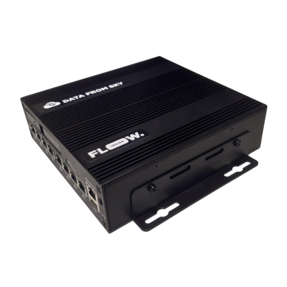
Page 6: Front Panel
HDD: HDD LED indicator. LED Indicator Fail: System Fail LED indicator. PoE ports (10/100 MbE, total 75W) for connecting to the IP cameras PoE Ports or other PoE devices. USB2.0 USB2.0 USB2.0 port. port. Power Indicator Power LED indicator. TrafficXRoads: Guide page 5... -
Page 7: Rear Panel
USB3.0 port. HDMI Port HDMI display output. RS-232 Port COM port for RS-232. RS-485 Port COM port for RS-485. Alarm IO Provides 4 alarm inputs and 4 alarm outputs. DC Power Input Connecting to the power source page 6 TrafficXRoads: Guide... -
Page 8: Carrier Board
Main Board: 170 x 179.3 x 35 mm / 6.7" x 7.1" x 1.38" Power Board: 30.1 x 98 x 25 mm / 1.19" x 3.85" x 0.98" IO Board: 45 x 98.3 x 18 mm / 1.77" x 3.87" x 0.71" TrafficXRoads: Guide page 7... -
Page 9: Mounting
Mounting TrafficXRoad is possible to screw it via L – bar or attach on DIN rails. Conection via screw Conection via DIN rails page 8 TrafficXRoads: Guide... - Page 10 Field installation Power source TrafficXRoads is powered by 12-24 DC power source. Unload device needs minimum 65W and every camera you connect use 5W – 15W extra power. We recommend you 100W power source. Device is powered by 3 wires:...
-
Page 11: System Web Interface And Network Settings
System web interface and network settings TrafficXRoads unit can be deployed in different scenarios and with different network setups. The web administration interface allows you to configure network settings, VPN and do the reboot or factory reset of the unit. By default, the unit has static IP address 192.168.50.10 and the web administration interface can be accessed using the URL:... - Page 12 For the Ethernet Interface you can enable/disable the loading of IP address from the DHCP server and set up individual static IP addresses (up to 4) and DNS servers (up to 3). We recommend using static IP addresses in real world deployments. TrafficXRoads: Guide page 11...
- Page 13 The unit also has a Wireguad or OpenVPN client VPN network. These VPN networks can be configured by the user as needed. The configuration for both VPN networks is done by uploading a text configuration file according to the requirements of the specific VPN. page 12 TrafficXRoads: Guide...
- Page 14 TrafficXRoads: Guide page 13...
-
Page 15: Flow - Connect And Define Traffic Analytics
There you should choose the correct version of FLOW Insights to match the version of the FLOW running on the TrafficXRoads device. If you have the latest version of FLOW installed on your device, you can get the latest FLOW Insights version here: http://www.datafromsky.com/download/flow/demokit/FLOW_Demokit.exe... - Page 16 Note that you should change this password when you log into FLOW insights in the user settings section. How to add the camera streams / analytics We are now communicating with the TrafficXRoads unit and you can start configuring it. First, we need to add a source camera stream. TrafficXRoads: Guide...
- Page 17 RTSP address is correct. You can connect the other camera streams that you want to analyze with the particular TrafficXRoads unit the same way. Maximum number of camera streams The unit is capable to process a certain number of FPS based on the provided/selected video analytics engine.
- Page 18 When the camera is in this position, the analytic will be running. In the moment when the camera leaves this position, no more trajectories will be received but the analytical engine will keep running. This TrafficXRoads: Guide page 17...
-
Page 19: Detection Of Traffic Events
In this document we will focus only on the selected basic tasks that can be used in detection systems for traffic control. The Definition of detection of traffic events is done in the Definition tab. page 18 TrafficXRoads: Guide... - Page 20 Next, we move the zone with the drag and drop technique into the right side panel, also referred to as workspace, which will instantiate it and the zone will start automatically filtering the trajectories from within the FLOW device cache. TrafficXRoads: Guide page 19...
- Page 21 After activating the NOW mode, you will see a number on the output of the zone that represents the current number of vehicles present in the zone. In this configuration the zone reacts to all objects that the system is able to detect. page 20 TrafficXRoads: Guide...
- Page 22 You can create any number of detection zones you like based on the needs of dynamic traffic control. All the zones can be connected to the same category filter. TrafficXRoads: Guide page 21...
- Page 23 – both data interfaces and physical interfaces (such as relay interface). The TrafficXRoads unit support multiple data interfaces including REST API, WEBHOOKs and UDP. For the data communication between the unit and the controller to work, the controller needs to support the specific data communication interface.
- Page 24 The list of the created UDP sinks can be found in the analytics and is available on the Diagnostics page. The status of the zone is communicated to the controller under the names listed in the Name row in the table. TrafficXRoads: Guide page 23...
- Page 25 IO interfaces section. A pop up window will show up with a list of supported I/O modules where you need to select the correct type of I/O module and confirm the choice by clicking on Add an interface. page 24 TrafficXRoads: Guide...
- Page 26 FLOW device will attempt to communicate with the I/O module. This action will return us to the Interfaces section where under the Status field you can tell whether the communication with the I/O module has been established succesfully. TrafficXRoads: Guide page 25...
- Page 27 By configuring the output we mean the Naming (under Name field), assigning physical relay (Output ID field) and the definition of control rule for ON/OFF (Output definition field). page 26 TrafficXRoads: Guide...
- Page 28 In the expression definition the widgets from individual defined analytics will be atomatically made available for the use. By clicking on the name of the widget you add it into the expression. The expression widget has full Javascript language support, so it is TrafficXRoads: Guide page 27...
- Page 29 Call data and Diagnostic requests from the CU. The FLOW unit can connect to its Ethernet port. By sending UDP packets in a specific format, it can change the content of the converter's responses on the SDLC bus. page 28 TrafficXRoads: Guide...
- Page 30 Command IP address - The IP address of the embedded unit. The convertor will discard all messages coming from a different IP address. Command UDP port - The port where the embedded unit will send commands for the converter and receive responses from. TrafficXRoads: Guide page 29...
- Page 31 After the correct set up of the communication interface with the SDLC unit, the configuration logic is the same as with the Relay interface. For the different input channels, you define expressions utilizing the published traffic data from widgets on dashboards of the individual analytics. page 30 TrafficXRoads: Guide...
-
Page 32: Reducing Latency
Connect the cameras directly to the unit if it is possible. Reducing processing latency in TrafficXRoads The FLOW framework enables configuration of different settings that lead to significant reductions in processing latency. - Page 33 High frequency (low tick interval) leads to higher processing load on the FLOW device and reduces reaction time. Lowest possible value is 100 ms. By default, the value is set to 333 ms. For traffic control tasks we recommend 100 ms. page 32 TrafficXRoads: Guide...
- Page 34 Processing). It concerns only the time it takes to process the image/evaluate the trajectories (including the tracker buffer). The value in the Insights -> Block section are not important for the communication with the controller, they only relate to the data transfer into the FLOW Insights configuration application. TrafficXRoads: Guide page 33...
- Page 35 Camera: ~ 50 – 150 ms Image transfer: < 10 ms (local network) TrafficXroads: ~100 ms Communication to traffic controller: < 1 ms (UDP, local network) Lower latencies are achievable with the use of industrial cameras (even as low as 50ms).
-
Page 36: More About Flow Framework
More about FLOW framework FLOW framework is a complex system that supports a variety of hardware devices. FLOW currently runs on TrafficCamera, TrafficEmbedded, TrafficXRoads, TrafficEnterprise and TrafficDrone (mobile processing unit). No matter the hardware requirements or use case you are able to work in the same system. The complete and up-to-date manual about all aspects of FLOW framework is available online at https://intercom.help/datafromsky/en/collections/2019942-flow-and-flow-insights... - Page 37 Some general guidelines that you may find useful on how to capture video can be found here: https://intercom.help/datafromsky/en/collections/2232238-general-faq In case you have not found what you have been looking for please get in touch with us using the live chat or send us email to support@datafromsky.com. page 36 TrafficXRoads: Guide...
-
Page 38: Conclusion
Inside FLOW Insights you will be notified when new FLOW version is available, however please do not update FLOW Insights without updating the TrafficXRoads unit first. If you would like to update the version of FLOW on your TrafficXRoads unit please get in touch with us at support@datafromsky.com. -
Page 39: Technical Specification
Technical specification XRoads V008 page 38 TrafficXRoads: Guide... - Page 40 Technical specification XRoads B000 TrafficXRoads: Guide page 39...
Need help?
Do you have a question about the TrafficXRoads and is the answer not in the manual?
Questions and answers