Table of Contents
Advertisement
Quick Links
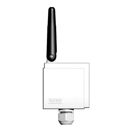
Open-To-Wireless™ Wireless Receiver
Product Description
This document describes the hardware installation procedure for the Open-to-Wireless™ Wireless Receiver. This device uses the EnOcean® protocol for
wireless communication.
The Open-to-Wireless Wireless Receiver enables Open-to-Wireless ready controllers to receive input signals from wireless battery-less sensors and
switches. The use of wireless devices minimizes impact on building structure, preserves original architecture and materials, and saves time and costs as-
sociated with re-wiring. Moreover, having a Wireless Receiver increases controller input count and makes field upgrades simple and straightforward.
The Wireless Receiver can be installed in multiple ways. For example, it can be mounted on a surface using double-sided tape or on the exterior of a
metal enclosure using a ½-inch NPT hub. However, the Wireless Receiver performs best when the antenna is elongated and away from metal objects or
surfaces more than 1" (2.5 cm) away from metal. A 6.5 ft (2 m) long cord is provided with the Wireless Receiver to connect to the controller.
This document describes the hardware installation procedures for the 902 and 868MHz Wireless Receiver models. It is recommended that you also refer
to the Open-to-Wireless Solution Application Guide for more detailed information on how to plan and install any wireless sensor and switch network.
General Installation Requirements
For proper installation and subsequent operation of the Wireless Receiver, pay special attention to the following recommendations:
£
Upon unpacking, inspect the contents of the carton for shipping damages. Do not install a damaged device.
£
The device is designed to operate under the following environmental conditions:
– Ambient temperature from 32°F to 122°F (0°C to 50°C)
– Relative humidity from 0% to 90%, non-condensing
£
Before installation, verify that local communication regulations allow the operation of wireless devices that communicate at the frequency of the
Wireless Receiver. For more information on transmission norms in different countries, refer to the Open-to-Wireless Solution Guide.
£
Ensure proper ventilation of the device and avoid areas where corroding, deteriorating or explosive vapors, fumes or gases may be present.
Any type of modification to any Distech Controls product will void the product's warranty
Take reasonable precautions to prevent electrostatic discharge to the device when installing, servicing or during operation. Discharge
accumulated static electricity by touching one's hand to a well-grounded object before working with the device.
The 868MHz model is a category 2 receiver. For the 868MHz model only:
£
Center frequency: 868.3MHz
£
Occupied frequency band: 868.0 – 868.6MHz
£
Maximum transmission power: 3dBm
For the 902MHz model only:
£
Center frequency: 902.875MHz
£
Occupied frequency band: 902.7-903.0MHz
£
Maximum transmission power: 1dBm
Figure 1:
Open-To-Wireless™ Wireless Receiver
I n s t a l l a t i o n G u i d e
Advertisement
Table of Contents

Subscribe to Our Youtube Channel
Summary of Contents for Distech Controls Open-To-Wireless Wireless Receiver
- Page 1 The Open-to-Wireless Wireless Receiver enables Open-to-Wireless ready controllers to receive input signals from wireless battery-less sensors and switches. The use of wireless devices minimizes impact on building structure, preserves original architecture and materials, and saves time and costs as- sociated with re-wiring.
- Page 2 Mounting Instructions The Wireless Receiver can be mounted on a ceiling or wall using screws or double-sided tape, or on a metal enclosure using a ½-inch NPT hub. Which- ever method is used, the Wireless Receiver should be 16” (41 cm) or more away from any network communication cables and, consequently, not too close to the controller.
- Page 3 Figure 4: Mounting the Wireless Receiver on a metal enclosure The Wireless Receiver is connected to the controller’s wireless port with the supplied 6.5 ft (2 m) cable. The Wireless Receiver’s socket is located inside the device. To locate it, open the Wireless Receiver by separating its front and back plates. Figure 5: Location of the Wireless Receiver’s socket Do not substitute with a cable from other sources.
- Page 4 Wireless Receiver Dimensions Wireless Equipment Mounting Considerations Preserving Signal Strength When installing the wireless equipment, it is important to ensure that distances and obstructions do not impede transmission. Metallic parts, such as rein- forcement in walls, machinery, office furniture, etc. are major sources of field strength dampening. Furthermore, supply areas and elevator shafts should be considered as complete transmission screens (See the next figure for radio wave screening).
- Page 5 Signal Transmission Quality Testing Even under screening conditions, Distech Controls strongly recommends that you always test the signal strength regardless of the range distance be- cause radio signals and transmission range can vary according to building and office setup. To verify the signal strength in any installation, use the RSSI feature with EC‑...
- Page 6 CEILING Both the sender and Relocate sender or Relocate sender or receiver should NOT receiver receiver be on the same axis Side View FLOOR Tx: Transmitter Rx: Receiver Figure 10: Wireless Receiver Ceiling Installation Unrelated transmitters (cell phone, GSM/DECT, WiFi, cordless phones, RFID reader) should be more than 6.5 ft (2 m) away from the receiver to avoid possible interference.
- Page 7 This example shows a typical metal relay panel/utility box installation: Antenna & receiver installed on top or side of panel Antenna & receiver installed directly on metal panel should be avoided Antenna & receiver NOT to be installed inside the panel Figure 14: Receiver Position with Metal Relay Panel Utility Box This example shows a typical fan coil unit installation:...
- Page 8 ©, Distech Controls Inc., . All rights reserved. Images are simulated. While all efforts have been made to verify the accuracy of information in this manual, Distech Controls is not responsible for damages or claims arising from the use of this manual.
Need help?
Do you have a question about the Open-To-Wireless Wireless Receiver and is the answer not in the manual?
Questions and answers