Acoustic Research AW851 - Outdoor Lantern And Wireless Speaker Manual
- Installation and operation manual (2 pages)
Advertisement
- 1 Introduction
- 2 Important Information
- 3 Important Safety Instructions
- 4 Care and Maintenance
- 5 Product Information
- 6 Recommended Installation Location
- 7 Setting Up
- 8 Tour of the Speaker System
- 9 Pairing the Speaker System
- 10 Turning the Speaker Off
- 11 Turning the Lamp On and Off
- 12 More Helpful Information
- 13 Troubleshooting
- 14 Specifications
- 15 Documents / Resources
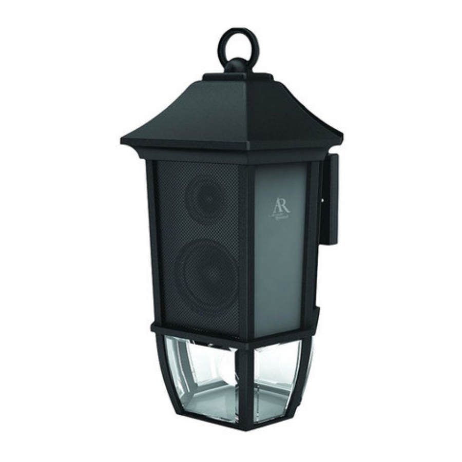
Introduction
AR's Outdoor Lantern and Wireless Speaker System puts a new twist on your outdoor lighting: sound! The AW851 eliminates the hardest part of adding speakers to your home—running and hiding hundreds of feet of speaker wire. The AR Wireless Speaker System's RF signal travels with ease through walls, fl oors, ceilings and other obstacles, delivering high-quality sound and stylish décor. With drift- and static-free reception along with outstanding range—up to 150 feet*—the possibilities for enjoying your AR Wireless Speaker System are nearly unlimited. The AR Wireless Speaker System is compatible with most audio sources, such as TVs, DVD players, VCRs, A/V receivers/ amps, stereos, computers, and portable devices (CD players, cassette players, MP3s etc.).
This manual covers various connection options and detailed operating instructions for making the AR Wireless Speaker System a valued part of your lifestyle. If, after having reviewed the instructions, you have any questions, please call toll-free 1-800-732-6866 or visit www.araccessories.com.
*Range may vary according to environment.
Important Information

RISK OF ELECTRIC SHOCK
DO NOT OPEN
To reduce the risk of electric shock, do not remove cover (or back). No user serviceable parts inside. Refer servicing to qualified service personnel.
 The Lightning flash with arrowhead symbol, with an equilateral triangle is intended to alert the user of the presence of uninsulated dangerous voltage within the product's enclosure that may be of sufficient magnitude to constitute a risk of electric shock to persons.
 The exclamation point within an equilateral triangle is intended to alert the user of the presence of important operating and maintenance (servicing) instructions in the literature accompanying the appliance.
For power rating and all applicable warning labels, see the bottom and the side of the transmitter and receiver/speaker.
Important Safety Instructions
- Read these instructions.
- Keep these instructions.
- Heed all warnings.
- Follow all instructions.
- Clean only with dry cloth.
- Do not block any ventilation openings. Install in accordance with the manufacturer's instructions.
- Do not install near any heat sources such as radiators, heat registers, stoves, or other apparatus (including amplifi ers) that produce heat.
- Protect the power cord from being walked on or pinched particularly at plugs, con ve nience re cep ta cles, and the point where they exit from the apparatus.
- Unplug this apparatus during lightning storms or when unused for long periods of time.
- Refer all servicing to qualifi ed service personnel. Servicing is required when the apparatus has been dam aged in any way, such as power-supply cord or plug is damaged, liquid has been spilled or objects have fallen into the apparatus, the ap pa ra tus has been exposed to rain or moisture, does not op er ate normally, or has been dropped.
- Only use attachments/accessories specifi ed by the manufacturer.
Care and Maintenance
- Always use a soft cloth to clean the speaker and transmitter. Never use any product containing alcohol or other solvents as they may damage the surface.
- Use caution when plugging the power transformer in an AC outlet to avoid the risk of electric shock.
- To clean the lantern/speaker: Shut off main power supply. Wipe with damp cloth or use window cleaner. Do not use abrasive cleaners.
- Bulb replacement: Replace with MAX 40W type B or Listed 13W Self-Ballasted Compact Fluorescent Lamp (candelabra-based bulb).

Do not use bulb-base adapters with this product. This product must be used with candelabra-based bulbs only.
Product Information
| Keep your sales receipt to obtain warranty parts and service and for proof of purchase. Attach it here and record the serial and model numbers in case you need them. These num bers are located on the product. Model No.: Purchase Date: Dealer/Address/Phone: |
RISK OF INJURY
- Some metal parts in the fixture may have sharp edges. To prevent cuts and scrapes, wear gloves when handling the parts.
- Account for small parts and destroy packing material, as these may be hazardous to children.
- Use flashlight or alternate light source to light work area during installation.
- Assistance may be required to support fixture during installation.
- This apparatus must be installed in accordance with all applicable installation rules.
- This device must be connected to a mains socket outlet or outlet box with a grounded and protected connection.
- To prevent injury, this apparatus must be securely attached to the wall in accordance with the installation instructions.
WIRING AND FIXTURE OPERATION
- Connect fixture to supply wires rated for at least 90°C (194°F).
- Do not use fixture on dimming circuits.
- Unit must be mounted higher than 60".
To prevent injury, this apparatus must be securely attached to the wall in accordance with the installation instructions.
Recommended Installation Location

Install your outdoor lantern and wireless speaker under eaves that extend at least 1 meter (3ft 11in) from your house and are at least 3 meters (9ft 10in) off the ground. Then make sure the bottom of the outdoor lantern and wireless speaker is at least 1.8 meters (5ft 6in) off the ground.
The outdoor lantern and wireless speaker must be mounted to a wall made of wood or concrete.
Setting Up
Unpacking
Before you start installing the Outdoor Lantern and Wireless Speaker, make sure you have the following parts in your package:

Mounting the Lantern/Wireless Speaker
Before you can use the Outdoor Lantern and Wireless Speaker, you must mount it to an outlet box.
Consult a qualified electrician in case the main supply wiring needs to be checked or if you're not certain how to install wiring. Always install wiring connections in accordance with local code, ordinances, and the National Electrical Code.
- Make sure power is off for the outlet box at the main circuit breaker.
- Remove the old fixture from the outlet box. Carefully disconnect its wiring.
![]()
- Mount the crossbar to the outlet box using the mounting screws included in this package.
- Unscrew the center screw on the crossbar and align the two side screws so that they are level with each other. Then tighten the center screw.
![]()
- Find the copper ground wire coming from the wireless speaker. Twist it together with the ground wire coming from the outlet box.
If the outlet box doesn't have a ground wire, attach the ground wire to the mounting crossbar as shown here.
![]()
- Strip 3/4" of insulation from the wire ends coming from the speaker. Use pliers to twist the speaker's stripped ends together with the wires coming from the outlet box—make sure you match black wire to black and white wire to white. Then snip the ends.
- Attach the wire connectors to the joined ends. If you'd like, you can tie the connectors and ends together with electrical tape.
![]()
- Place the wireless speaker onto the two side screws on the crossbar. Secure the speaker onto the wall with the two caps included in this package.
![]()
- Use silicon caulking to seal the top and sides between the speaker and the wall. Leave the bottom open so that moisture can drain.


Connecting the Transmitter to an Audio Source
- Plug the stereo plugs on the provided Y-adapter audio cable into the AUDIO IN jacks on the back of the transmitter (make sure to match the colors on the plugs and jacks).
- Plug the mini-plug end of the provided Y-adapter into the headphone output of your MP3 player or CD player (or audio output jack on your computer).
![]()
![]()
This product is designed to work with line level outputs or headphone outputs only. DO NOT connect it directly to speaker outputs as it will permanently damage the transmitter.
- Connect the small, round plug from the transmitter AC power adapter to the transmitter's DC IN jack. Plug the other end of the transmitter AC power adapter into any standard 120V AC wall outlet.
![]()


Note: This power unit is intended to be correctly oriented in a vertical or fl oor mount position.
Note: There is no transmitter ON/OFF switch. The transmitter is designed to be left plugged in and powered at all times. If you will not be using the AW851 for an extended period of time, unplug the transmitter AC power adapter.
| Connecting to an A/V Receiver You can also connect the transmitter to an A/V Receiver using the mini-jack to RCA adapter included.
|

Installing/Changing the Lantern Light Bulb
The Outdoor Lantern and Wireless Speaker takes a candelabra-base bulb (40W max; bulb not included). The bottom of this Outdoor Lantern and Wireless Speaker is open for easy access to the socket. For best results, use a clear (non-frosted) 40W bulb. To install or change the lantern's bulb:
- Find the light socket located on the bottom of the lantern.
- Insert the bulb and screw it into the socket.


Handle and dispose of fl uorescent bulbs per manufacturer's directions.
Tour of the Speaker System
Lantern/Speaker
Right Panel Speaker Controls

Right Side, Back
Speaker On/Off button turns the speaker on and off
Auto Scan button rescans for the transmitter's signal
Volume Up and Down buttons adjust the volume level
L/Mono/R switch determines if the speaker plays sound in mono as a stand-alone speaker, or plays the left or right track in a stereo pair with an additional AW851
Light On/Off switch turns the lantern on and off
Front Panel
Power/Linked indicator (not shown) blinks when the speaker is fi rst powered on; it turns solid blue when the speaker is tuned to the transmitter
Transmitter

SIGNAL indicator lights green when the audio is present and the transmitter is broadcasting POWER indicator lights when the transmitter is on
CHANNEL 1 2 3 lets you fi nd the best transmission frequency for your environment
DC IN jack receives the small round end of the included 12V 200mA AC power adapter
AUDIO IN (R / L) connects to your sound source using one of the connection options shown on the next pages
Pairing the Speaker System
Adjusting the Transmitter
- Turn on your audio source (for example, A/V receiver, MP3 player, stereo, etc.) and play music at a normal listening volume.
- Set the channel select switch on the back of the transmitter to one of the transmitter's three broadcast frequencies: 1, 2 or 3. If you experience poor reception or interference, try choosing a different frequency by moving the channel select switch to another position.
![]()
When the transmitter is receiving an audio signal and is ready, the SIGNAL indicator turns solid green.

Note
If the SIGNAL indicator on the transmitter does not turn on, please check the following:
- Confirm the transmitter AC power adapter is securely connected.
- Confirm the cable from the transmitter is securely connected to the audio source output (MP3 player, A/V receiver, etc.).
- Confirm the audio source is playing audio and is turned up.
Tuning the Speaker

- Press the Speaker On/Off button on the right side of the speaker to turn it on. The indicator light on the front of the speaker blinks while the speaker is tuning to the transmitter. The indicator light turns solid blue when the speaker is tuned to the transmitter—you should hear sound coming from the speaker now.
![warning]() Note: If the speaker is on a switched outlet, make sure the outlet is on.
Note: If the speaker is on a switched outlet, make sure the outlet is on.
![warning]() Note: If the speaker is not tuned or if the transmitter is not connected properly, the indicator light will continue blinking. If this occurs, please see the troubleshooting section of this manual.
Note: If the speaker is not tuned or if the transmitter is not connected properly, the indicator light will continue blinking. If this occurs, please see the troubleshooting section of this manual. - Adjust the volume on the speaker as desired.
- Set up the speaker for mono or stereo operation using the switch on the right side of the AW851 speaker.
- Monaural operation: The monaural mode (mono) is recommended when using a single AW851 by itself. For monaural operation, set the L/M/R switch to "M" on the speaker.
- Stereo operation: You need an additional AW851 speaker for the stereo option. Set the L/Mono/R switch to "L" on the speaker located to the left from the listener, and set the other speaker to the "R" position.
Notes:
A single AW851 transmitter can send its signal to more than two speakers. All you need to do is tune the speakers to the single transmitter.
The speaker automatically retunes if it loses the transmitter's signal. You can also press the Auto Scan button on the bottom of the speaker to retune the speaker at any time.
The transmitter turns off automatically if there is no audio signal present for a prolonged period.
Interference in the form of static and/or distortion can sometimes be heard. If this occurs, confi rm the transmitter/speaker adjustments and indicators. If the problem persists, refer to the Troubleshooting section of this manual.
Turning the Speaker Off
- Press Speaker On/Off button on the bottom of the speaker to turn the speaker off.
- Confi rm that the speaker is off by verifying that the indicator light on the speaker's front panel is no longer illuminated.
Turning the Lamp On and Off
To turn the lamp on: Put the Light On/Off switch on the bottom of the speaker in the on position. If the lamp is on a switched outlet, make sure the outlet is on.
To turn the lamp off: Put the Light On/Off switch on the bottom of the speaker in the off position.
More Helpful Information
About Fixed-Level Audio Outputs
A fixed-level, or line-level, audio output is considered ideal since it provides an audio signal unchanged by adjustments to the audio source volume control.
 Hint: Fixed-level audio outputs from stereo receivers/amps will typically be designated as Tape (or Record) outputs or DVR/DVD-R audio output connections.
Fixed-level outputs from TVs are usually marked as 'Constant,' 'Fixed,' or 'Select.' If they are not marked as such, they are probably variable outputs (see "About Variable-Level Audio Outputs" below). Outputs from DVD players are almost always fixed.
Hint: When connecting to the audio outputs of a DVD player, remember that the DVD player must be showing a TV channel for sound to be produced.
About Variable-Level Audio Outputs
A variable-level output, such as a headphone jack or certain RCA-type outputs, provides an audio signal that changes with the volume level set on the audio source. As the volume of the audio source is adjusted up and down, so is the audio signal strength sent to the transmitter. This can affect the quality of sound generated by the speaker, and may require an adjustment of the volume level of the audio source to produce a signal strong enough for the transmitter.
Hint: On most bookshelf-type or compact stereo systems, inserting a headphone plug into the headphone jack results in automatic cutoff of the regular, or hard-wired speakers.
Hint: Most TVs, regardless of age or price, have variable outputs. If you are unsure which of your TV audio outputs is fixed, refer to the TV instruction manual. Some TVs have outputs that can switch between variable and fixed. When given a choice, fixed is always recommended.
Troubleshooting
The following troubleshooting guide takes you through some of the more common problems associated with the installation and/or operation of a wireless system. If the problem persists, please call toll-free at 1-800-732-6866 or visit www.araccessories.com.
| Issue: | Cause and solution: |
| No sound |
|
| No sound/ distortion/ static |
|
| Bulb doesn't light |
|
| Circuit breaker trips when you turn on the lantern |
|
Specifications
Transmitter
- Omni-directional 900MHz broadcast
- Effective transmitting range: up to 150 ft. (45m)*
- Phase-locked loop circuitry (PLL)
- Automatic level control (ALC)
- 3 selectable broadcast frequencies
- Stereo audio input
*Maximum range; results may vary according to environment.
Speaker
- Push-button, auto-lock tuning
- 2-way acoustic design:
2" tweeter, 3" woofer - 5 Watt RMS internal amplifi er
- Omni-directional sound
- Frequency response: 40Hz - 15kHz
- Left/Mono/Right switch
- Operates using AC outlet box (requires installation)

Documents / Resources
References
Download manual
Here you can download full pdf version of manual, it may contain additional safety instructions, warranty information, FCC rules, etc.
Download Acoustic Research AW851 - Outdoor Lantern And Wireless Speaker Manual
Advertisement

Need help?
Do you have a question about the AW851 and is the answer not in the manual?
Questions and answers