Table of Contents
Advertisement
Quick Links
Advertisement
Table of Contents

Summary of Contents for QKM QD1
- Page 2 User Manual QD1 IO Expansion Module Modular & Economical Document Version V3.1.0 Issue Date 18/08/2020 QKM Technology (Dongguan) Co., Ltd.
- Page 3 Read this manual carefully before using QD1. Keep this manual properly for future reference. Overview This manual provides the basic information, module composition, work principle, installation and configuration guidance of QD1 products for users to fully understand and use them. Readers This manual applies to:...
- Page 4 Without the written authorization of QKM, no unit or individual shall extract or copy the contents of this document; and shall not directly or indirectly reproduce, manufacture, process and use this product and related parts.
- Page 5 Version History Version History The version history contains the accumulated information on each update of the document, and the latest version of the document includes the updates in all previous versions of the document. Version Date Content V1.0.0 18/08/2020 The first version was officially released. Document Version V3.1.0 (2020-08-18)
-
Page 7: Table Of Contents
Contents Contents Preface..........................I Version History ......................III Description of Terms ....................VIII Chapter 1 Product Overview ................... 1 1.1 Introduction of components ................2 1.1.1 Modular type ..................... 2 1.1.2 Economical type ..................3 1.2 Product dimensions .................... 4 1.2.1 Modular type ..................... - Page 8 4.2.1 Network connection ................28 4.2.2 Configuration for connection to Web Server ........... 29 4.2.3 Web Interface IO control ................. 31 4.2.4 Call QD1 instruction in GDE ..............32 4.3 Configuration for connection to PC ..............32 4.3.1 PC configuration ..................32 4.3.2 File load configuration ................
- Page 9 Contents 4.4 Dynamic library configuration ................47 Appendix A FAQ ......................49 Document Version V3.1.0 (2020-08-18)
-
Page 10: Description Of Terms
QD1 IO Expansion Module User Manual Description of Terms The special terms in this manual are described as follows: Term Description Quotient Kinematics Machine QKM Digital Input and Output Guidance Development Environment Input & output Digital intput Digital output Light Emitting Diode... -
Page 11: Chapter 1 Product Overview
IO channels to support bus expansion. QD1 supports Modbus TCP commonly used in the industry. Main controller can access and control each IO channel upon connection to QD1 with network cable. QD1 module has dual RJ45 network ports with native routing and forwarding function, and can be flexibly and freely networked with main controller via cascade communication or daisy chain topology. -
Page 12: Introduction Of Components
1.1 Introduction of components 1.1.1 Modular type The components of modular QD1 are detailed in Figure 1-4. Modular QD1 (16 In/16 Out) has the same power interface and network ports as modular QD1 (32 In/32 Out). Output Work LED (green) -
Page 13: Economical Type
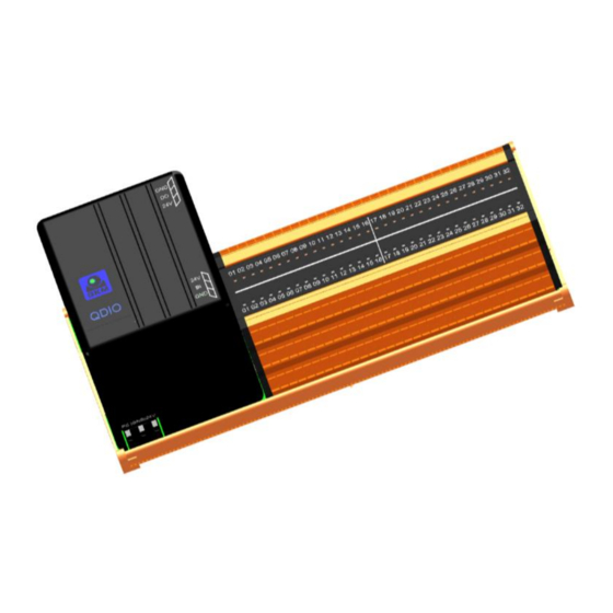
Chapter 1 Product Overview LAN1/LAN2 Communication port Figure 1-5 Back view of modular QD1 (32 In/32 Out) 1.1.2 Economical type Economical QD1 consists of a motherboard and a daughterboard with components detailed in Figure 1-6 and Figure 1-7: Power interface IO interface Fuse... -
Page 14: Product Dimensions
QD1 IO Expansion Module User Manual Figure 1-7 Daughterboard of economical QD1 1.2 Product dimensions 1.2.1 Modular type Figure 1-8 Dimensions of modular QD1 (32 In/32 Out) (unit: mm) Document Version V3.0 (2020-08-18) -
Page 15: Economical Type
Chapter 1 Product Overview Figure 1-9 Dimensions of modular QD1 (16 In/16 Out) (unit: mm) 1.2.2 Economical type Figure 1-10 Dimensions of QD1 motherboard (unit: mm) Figure 1-11 Dimensions of QD1 daughterboard (unit: mm) Document Version V3.1.0 (2020-08-18) -
Page 16: Technical Parameters
Output mode NPN mode NPN mode Output drive 200 mA (continuous) 200 mA (continuous) capability 1.3.2 Dimension parameters Table 1-2 Dimension parameters of QD1 product (unit: mm) Modular type Modular type Item Economical type (32 In/32 Out) (16 In/16 Out) Dimensions... -
Page 17: Installation Environment
Chapter 1 Product Overview 1.3.3 Installation environment Install the product in an environment that meets the following conditions to exploit /maintain its performance and use it safely. Table 1-3 QD1 working environment parameters Installation Remark environment Working 0℃ ~ +55℃... -
Page 18: Chapter 2 Work Principle
2.1 Communication networking QD1 supports Modbus TCP protocol communication. Main controller can access and control each IO channel upon connection to QD1 with network cable; QD1 module has dual RJ45 ports and native routing & forwarding function for free forwarding at 10/100 M network, and can flexibly communicate with main controller via cascade communication or daisy chain topology. -
Page 19: Modular Type
Chapter 2 Work Principle 2.1.1 Modular type 16- or 32-channel DO 16- or 32-channel DI Figure 2-1 Modular QD1 networking diagram 2.1.2 Economical type Unlimited expansion Figure 2-2 Economical QD1 networking diagram Document Version V3.1.0 (2020-08-18) -
Page 20: Definition Of Io Pins
QD1 IO Expansion Module User Manual 2.2 Definition of IO pins 2.2.1 Modular type Figure 2-3 Modular QD1 interfaces of 32 In/32 Out (top view) Figure 2-4 Modular QD1 interfaces of 16 In/16 Out (top view) Document Version V3.0 (2020-08-18) -
Page 21: Economical Type
Chapter 2 Work Principle Table 2-1 Description of modular QD1 interfaces Interface Module Signal Function 32 In/32 Digital signal input 24 V DI 00~32 expansion 01~32 power 24 V supply interface 16 In/16 Digital signal input Common DI 00~16 expansion 01~16... - Page 22 24V power +24V ground supply Power 24V power +24V ground supply Do not connect an external power source to 0 V or 24 V port on the terminal block of economical QD1 to avoid burn out. Document Version V3.0 (2020-08-18)
-
Page 23: Digital Input (Di)
Chapter 2 Work Principle 2.3 Digital input (DI) 2.3.1 Modular type Modular QD1 supports 32- or 16-channel optocoupler-isolated digital input, and the input circuit diagram is shown in Figure 2-6. Controller User port Optocoupler-isolated DI Figure 2-6 Input circuit diagram of modular QD1 2.3.2 Economical type... -
Page 24: Digital Output (Do)
Figure 2-7 Input circuit diagram of economical QD1 2.4 Digital output (DO) 2.4.1 Modular type Modular QD1 supports 32- or 16-channel optocoupler-isolated digital output. Each channel has a rated output current of 200 mA, and the output circuit diagram is shown in Figure 2-8:... -
Page 25: Description Of Leds
Each channel has a rated output current of 200 mA, and the output circuit diagram is shown in Figure 2-9. Controller User port Optocoupler-isolated DO Figure 2-9 Output circuit diagram of economical QD1 2.5 Description of LEDs 2.5.1 Modular QD1 Work LED (Green) -
Page 26: Economical Qd1
QD1 IO Expansion Module User Manual Table 2-3 Description of modular QD1 LEDs Color Function Status description Work LED "NO" indicates the module works Green Work LED normally. (LED1) "NO" indicates that communication connection been established. Green "Flashing" indicates communication Communication is being performed (100 Mbit/s). - Page 27 Chapter 2 Work Principle Table 2-4 Description of QD1 LEDs Color Function Status description "NO" indicates the module works LED1 Green Work LED normally. "NO" indicates 3.3 V power supply LED2 Yellow Power LED works normally. "NO" indicates the module fails.
-
Page 28: Chapter 3 Product Installation
3.2.1 Installation of guide rail Step 1 Install the fixed buckle at one end of QD1 onto the guide rail. Step 2 Press down on the other end of QD1 to fix it to the guide rail, as shown in Figure 3-1:... - Page 29 Chapter 3 Product Installation Section 2.1. 2. Insert the RJ45 cable into the communication port of QD1, as shown in Figure 3-2: Communication port Figure 3-2 Installation of modular QD1 network cable Install the network cable according to configuration scenario and with reference to Section 2.1 Communication networking.
-
Page 30: Installation Of Power Wire
Step 1 Use a screwdriver to press down on the power interface and hold it. Step 2 Connect the DC power wire to the power interface of QD1. Step 3 Release the power interface and check whether the connection is firm, as... -
Page 31: Installation Of Daughterboards
Figure 3-5 Motherboard installation diagram (unit: mm) 3.3.2 Installation of daughterboards The single board of economical QD1 has 16 (input) * 16 (output) channels. One QD1 motherboard supports installation of up to 7 daughterboards. Upon expansion, it supports 32, 48, 64... 112 IO channels, which can flexibly meet users’... -
Page 32: Installation Of Communication Cable
3.3.3 Installation of communication cable Step 1 Installation of network cable 1. Install a communication cable according to Section 2.1 Communication networking. 2. Insert the communication cable into the RJ45 port of QD1, as shown in Figure 3-8: Document Version V3.0 (2020-08-18) - Page 33 Threading assembly Figure 3-9 Production of IO connector ⚫ If the QD1 product you choose to buy is not equipped with a standard IO plug, you can produce an IO plug by welding in this way. ⚫ When connecting IO signal wires to the connector by welding, the connector should match the motherboard/daughterboard of economical QD1 symmetrically.
-
Page 34: Installation Of Power Wire
Step 1 Use a screwdriver to press down on the power interface and hold it. Step 2 Connect 24 V d.c. power wire to the power interface of QD1. Step 3 Release the power interface and check whether the connection is firm, as... -
Page 35: Check After Installation
Chapter 3 Product Installation 3.4 Check after installation Check whether QD1 is installed correctly before configuration for normal use. To ensure safe and stable operation, please perform the following checks: ⚫ Check whether all fixing screws are tightened. ⚫ Check whether power wire is connected properly and firmly, and whether its positive and negative poles are connected in reverse. -
Page 36: Chapter 4 Configuration Before Use
4.1 Initialization configuration 4.1.1 IP address configuration Step 1 Connect QD1 to 24 V d.c. power supply. If the power LED is always on, it indicates that power is normally supplied to the module. Step 2 Connect PC to QD1 with network cable, and run the IPconfig.exe on the Figure 4-1 Run the IPconfig.exe... - Page 37 Chapter 4 Product Installation If you cannot view the IP address of the module after clicking the <Scan> button, click the <Settings> button to make configuration changes as shown below, and click the <OK> button. Then click the <Scan> button again.
-
Page 38: Ip Address Check
Prerequisites: GDE installed on computer; personnel familiar with operations on GDE. 4.2.1 Network connection QD1 can be quickly configured to connect with QKM robot controller. Connect QD1 to LAN where robot controller is located with network cable, which can be achieved via industrial switches, routers, etc. -
Page 39: Configuration For Connection To Web Server
Chapter 4 Product Installation 4.2.2 Configuration for connection to Web Server Step 1 Open webpage with IE browser. Enter the IP address (e.g. 192.168.01) of robot or controller in the address bar. If network connection is normal, click to enter the interface as shown in Figure 4-6. Figure 4-6 Open Web Server Step 2 Open <Administrator>, <Control Panel>... - Page 40 Step 2~Step 3 to configure Data ID 583 in Node2 Modbus TCP. ⚫ If configured for single motherboard of QD1, the QD1 motherboard supports a maximum of 16 IO channels, then modify its value to "192.168.2.247, 1:B, 16, 10101, 1:B, 16, 101".
-
Page 41: Web Interface Io Control
4.2.3 Web Interface IO control After configuring connection to Web Server, open <Control Panel>, <Remote I/O> and <RIO 1> in sequence, and the IO control of QD1 is displayed on the IO control panel of Web Interface. Document Version V3.1.0 (2020-08-18) -
Page 42: Call Qd1 Instruction In Gde
Visual Studio development environment. 4.3.1 PC configuration QD1 can be controlled via multiple terminals. Users can control QD1 via PC/host computer in addition to QKM robot. Install Visual Studio 2015 before configuring PC. The requirements for hardware installation are shown in Table 4-2 Requirements for hardware configuration: Document Version V3.0 (2020-08-18) -
Page 43: File Load Configuration
The following provide instructions for use based on win10/64-bit operating system, taking the creation of a console application as an example. Step 1 Connect PC to QD1 with network cable, as shown in Figure 4-10: Figure 4-10 Connect PC to QD1 Step 2 Open Visual Studio 2015 on your computer via “Blend.exe”... - Page 44 QD1 IO Expansion Module User Manual Figure 4-11 Open Visual Studio It may not open Win32 Console Application based on Win10 system, if you open Visual Studio 2015 directly via the icon. Please follow the step to run VS 2015.
- Page 45 Chapter 4 Product Installation Figure 4-12 Open Visual Studio 2. Click <Visual C++> in the New Project page and select Win32 Console Application, then modify the project name and click <OK>, as shown in Figure 4-13. Document Version V3.1.0 (2020-08-18)
- Page 46 QD1 IO Expansion Module User Manual Figure 4-13 Create Win32 Console Application Document Version V3.0 (2020-08-18)
- Page 47 Chapter 4 Product Installation 3. After clicking <Next>, Select Console Application and uncheck empty project, as shown in Figure 4-14. Figure 4-14 Application Settings If select empty project, you might not find the directory of C++ in property pages. Step 4 Add paths to include files and library files. 1.
- Page 48 QD1 IO Expansion Module User Manual Figure 4-15 Add paths to include files 2. Select all platforms. Figure 4-16 Select platforms 3. Then go back to property pages, click <VC++ Directories>, <include Document Version V3.0 (2020-08-18)
- Page 49 Chapter 4 Product Installation Directories> and <edit...> in sequence. Add paths to include files. After adding paths to include files, it will be shown in directory page. Figure 4-17 Add a path to include files 4. Go back to the property pages, click <VC++Directories>, <Library Directories>...
- Page 50 QD1 IO Expansion Module User Manual Step 5 Add paths to additional include files and set precompiled headers. 1. Go back to the property pages again, click the directory of <C/C++>, <General>, <Additional Include Directories> and <Edit...> in sequence, select paths to additional include files and confirm, as shown in Figure 4-19.
- Page 51 Chapter 4 Product Installation Step 6 Click <Linker>, <General>, <Additional Library Directories>, <Edit> in sequence, select paths to additional library files, as shown in Figure 4-21. Figure 4-21 Add a path to additional library files Document Version V3.1.0 (2020-08-18)
- Page 52 QD1 IO Expansion Module User Manual Step 7 Click <Linker>, <Input>, <Additional Dependencies>, and <Edit...> in sequence. Fill in modbus.lib, click <OK> and <Apply> as shown in Figure 4-22. Figure 4-22 Fill in modbus.lib Document Version V3.0 (2020-08-18)
- Page 53 Chapter 4 Product Installation Step 8 Search sysWOW64 folder on your computer, then copy Modbus.dll to the folder. ⚫ If you cannot find sysWOW64 folder, please search system32 on your computer, click <Windows> to return to upper level folder and you will find sysWOW64 folder. ⚫...
- Page 54 QD1 IO Expansion Module User Manual This library function is compiled based on libmodbus (open source library) function transplantation; more, visit http://libmodbus.org/. Configuration of key functions: Step 1 Create a new libmodbus environment. Use the modbus device linked by tcp and apply the modbus_new_tcp () function. If the new creation is successful, a struct modbus_t pointer will be returned.
- Page 55 Chapter 4 Product Installation Example: uint8_t bits[MAX_IO] = {0}; int ret, i; ret=modbus_read_bits(ctx,MODBUS_COIL_ADDR,MODBUS_COI L_LEN, bits); if (ret < 0) {fprintf(stderr, “%s\n”, modbus_strerror(errno)); } else {printf(“BITS COILS: \n”),for (i = 0; i < ret; i++) {printf(“[%d] = %d\n”, i, bits[i]); } } int modbus_read_input_bits(modbus_t *ctx, int addr, int nb, uint8_t *dest);...
- Page 56 { fprintf(stderr, “%s\n”, modbus_strerror(errno)); } int modbus_write_bit(modbus_t *ctx, int addr, int status); Write single IO/coil with function code of 0x05. This function can be used to perform write operations to QD1 slave stations. This function returns 0 on success and -1 on failure. Example: ret = modbus_write_bit(ctx, 5, TRUE);...
- Page 57 Heartbeat Package: A self-defined command word that periodically informs the other party of its own status between client and server, which is sent at a certain time interval (the time interval required by QD1 is within 60S), similar to heartbeat, so it's called heartbeat package.
- Page 58 QD1 IO Expansion Module User Manual You can create a thread for management. Example: #include <stdio.h> #include <string.h> #include <stdlib.h> #include <time.h> #include <winsock2.h> #include <windows.h> #include <process.h> #include "modbus.h" /* This can be any input, just to keep connection alive */...
- Page 59 Chapter 4 Product Installation /* Establish the connection over TCP */ ctx = modbus_new_tcp(MODBUS_SERVER_IP, MODBUS_SERVER_PORT); /* Create and start the backend thread */ hThread = (HANDLE)_beginthreadex(NULL, 0, &HeartBeat, ctx, 0, NULL); /* You can implement your own functions here... */ /* Free the connection and disable the thread */ modbus_close(ctx);...
- Page 61 Appendix A FAQ Appendix A FAQ This manual proposes solutions to some common problems during QD1 operation for better use of QD1 products by users: Q: Why is the yellow LED2 of economical QD1 not lit? A: Check whether the 24V power supply is properly connected and normally supplies power.
- Page 62 QD1 IO Expansion Module User Manual A1: Check the configured IP address to ensure that the IP addresses of robot and QD1 are on the same network segment. A2: Check whether the value of Date ID 582 in Setup → Parameter Database →...