Table of Contents
Advertisement
Quick Links
04/2023
500384H
WLAN-Box
Montage- und Betriebsanleitung | Installation and operating instructions
Produktbeschreibung
Die WLAN-Box dient zur drahtlosen Steuerung von
Produkten mit einer HAUTAU-Busschnittstelle per WLAN-
Funk s ignal. Die Steuerung erfolgt durch mobile End g eräte
über eine Direkt v erbindung zur WLAN-Box oder über
b auseitigeWLAN- R outer.ZurSteuerungund K onfiguration
der Produkte wird das optional erhältliche HAUTAU
C onfigToolbenötigt.
Inhaltsverzeichnis
Merkmale ................................................................................................. 3
Gewährleistung,Entsorgung ............................................................ 3
ZertifikateundErklärungen .............................................................. 3
AnwendungsbeispieleundLeitungsverlegeplan ....................... 4
Geräteübersicht ..................................................................................... 5
LeitungslängenundQuerschnitte ................................................... 6
HinweisefürHAUTAU-Bus ............................................................... 6
Montage der WLAN-Box ................................................................... 6
Anschlussplan ......................................................................................... 7
OptischeSignaleundTastenbelegung ........................................ 10
WLAN-Anmeldung .............................................................................. 11
Funktionsbeschreibung ..................................................................... 11
Technische Daten ................................................................................ 12
Originalanleitung | Original instructions
zur drahtlosen Steuerung von Produkten mit HAUTAU-Busschnittstelle
forwirelesscontrolofproductswithHAUTAUbusinterface
Product description
TheWLAN-Boxistobeusedforwirelesscontrolof p roducts
with a HAUTAU bus interface via WLAN radio signal.
The c ontrol will be effected by means of mobile t erminals
via a direct connection to the WLAN-Box or via on-site
WLAN r outers.Forcontrolandconfigurationoftheproducts,
theoptionalavailableHAUTAUConfigToolisrequired.
Table of content
Seite
Importantsafetyinstructions,Installationinformation .......... 2
Features .................................................................................................... 3
Warranty,Disposal................................................................................ 3
Certificatesanddeclarations ............................................................. 3
Application examples and wiring diagram ................................... 4
Equipmentoverview ............................................................................ 5
Wire lengths and cross-sections ...................................................... 6
InformationforHAUTAUbus ........................................................... 6
InstallationoftheWLAN-Box .......................................................... 6
Terminal connection diagram ........................................................... 7
Opticalsignalsandassignmentofkeys ...................................... 10
WLAN log-in .......................................................................................... 11
Functional description ........................................................................ 11
Technical data ....................................................................................... 12
DE | EN
page
Advertisement
Table of Contents

Summary of Contents for Maco HAUTAU WLAN-Box
-
Page 1: Table Of Contents
04/2023 500384H WLAN-Box zur drahtlosen Steuerung von Produkten mit HAUTAU-Busschnittstelle forwirelesscontrolofproductswithHAUTAUbusinterface DE | EN Montage- und Betriebsanleitung | Installation and operating instructions Produktbeschreibung Product description Die WLAN-Box dient zur drahtlosen Steuerung von TheWLAN-Boxistobeusedforwirelesscontrolof p roducts Produkten mit einer HAUTAU-Busschnittstelle per WLAN- with... -
Page 2: Wichtigesicherheitsanweisungen,Installationshinweise
WARNUNG: WARNING: Wichtige Sicherheits anweisungen! Important safety instructions! ACHTUNG! ATTENTION! Für die Sicherheit von Personen ist es wichtig, die The safety of personnel requires that the following folgenden Anweisungen zu befolgen. Falsche Montage instructions be observed. Incorrect installation can lead kann zu schweren Verletzungen oder zum Tod führen! to severe injury or to death! Die WLAN-Box entspricht dem aktuellen Stand... -
Page 3: Merkmale
Merkmale Features -zumEinbauineineUnter-Putz-Dose(UP) -forinstallationinaflushhousing - zur Steuerung von max. 31 Teilnehmern mit HAUTAU-Bus- - f orcontrolofmax.31participantswithHAUTAUbusinterface Schnittstelle - c ontrolandconfigurationbymeansofWLAN - S teuerungundKonfigurationperWLAN (WirelessLocalAreaNetwork) (WirelessLocalAreaNetwork) - s afedataexchangebymeansofWPAencryption - sicherer Datenaustausch per WPA Verschlüsselung (Wi-FiProtectedAccess) (Wi-FiProtectedAccess) - L ogonaton-siteroutersbymeansofWPS - A nmeldunganbauseitigeRouterperWPS (Wi-FiProtectedSetup) (Wi-FiProtectedSetup) -opticalsignalforfeedbackforoperationandconfiguration... -
Page 4: Anwendungsbeispiele Und Leitungsverlegeplan
Anwendungsbeispiele und Application examples and wiring diagram Leitungsverlegeplan Anwendungsbeispiel für 24 V DC-Antriebe (z. B. SKA 20 comfort drive) mit Direkt verbindung Application example for 24 V DC drives (e. g. SKA 20 comfort drive) with direct connection Betriebsspannung + 24 V DC 3 x 0,8 mm²... -
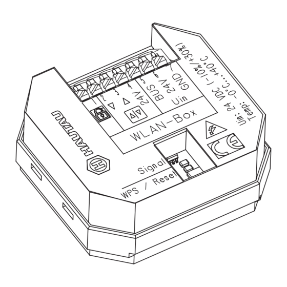
Page 5: Geräteübersicht
Anwendungsbeispiele und Application examples and Leitungsverlegeplan (Forts.) wiring diagram (cont‘d) Anwendungsbeispiel für 230 V AC-Antriebe (z. B. PRIMAT-E kompakt 195) mit Anbindung an bauseitigen WLAN-Router Application example for 230 V AC drives (e. g. PRIMAT-E kompakt 195) with connection to on-site WLAN router NYM 3 x 1,5 mm²... -
Page 6: Leitungslängen Und Querschnitte
Leitungslängen und Querschnitte Wire lengths and cross-sections Hinweise für 24 V Antriebe Information for 24 V drives DiemaximalenLeitungslängenvonderEnergiequellebiszur Themaximumwirelengthsfromtheenergysourceuntilthe letztenAbzweigdosesindgemäßdenverwendetenAder- last j unctionboxaretobeobservedacc.totheusedcable querschnittenundder m aximalenStromaufnahmejeAntriebs- cross- sections and the maximum current consumption per gruppe einzuhalten. drive group. Leitungsquerschnitt [mm²] Cable cross-section [mm²] Berechnungsformel: Calculation formula:... -
Page 7: Anschlussplan
Anschlussplan Terminal connection diagram Anschlussplan für 24 V DC Antriebe, Terminal connection for 24 V DC drives, Typ SKA 20 comfort drive und PRIMAT-S kompakt 195 version SKA 20 comfort drive and PRIMAT-S kompakt 195 Verriegelung Lüftungstaster SKA 20 comfort drive / PRIMAT-S kompakt 195 Locking Ventilation pushbutton +24 V DC... - Page 8 Anschlussplan (Forts.) Terminal connection diagram (cont‘d) Anschlussplan in Kombination eines Regenmelders Terminal connection in combination with a rain sensor REM/H 10 Lüftungstaster Regenmelder Ventilation pushbutton Rain sensor SKA 20 comfort drive / PRIMAT-S kompakt 195 1 2 3 4 1 2 3 4 5 +24 V DC 24 V DC Ö...
- Page 9 Anschlussplan (Forts.) Terminal connection diagram (cont‘d) Anschlussplan für mehrere 230 V AC Antriebe, Terminal connection diagram for several 230 V AC drive, Typ PRIMAT-E kompakt 195 version PRIMAT-E kompakt 195 230 V AC PRIMAT-E kompakt 195 PRIMAT-E kompakt 195 PRIMAT-E kompakt 195 Anschluss eines optionalen Lüftungstasters und eines 1 2 3 4...
-
Page 10: Optische Signale Und Tastenbelegung
Optische Signale und Tastenbelegung Optical signals and assignment of keys Optische Anzeige „Signal“ und Taste „WPS / Reset“ Opticaldisplay„Signal“andbutton„WPS/Reset“ Taste / Button Anzeige /Display Funktion / Function LED blinkt WLAN-Box in Betrieb LEDblinks WLAN-Box in operation kurz gedrückt (< 1 s) LED an WPS-Anmeldung pressedshortly(<1sec.) -
Page 11: Wlan-Anmeldung
WLAN-Anmeldung WLAN log-in DieWLAN-Boxmussbetriebsfertigmontiertundaneiner TheWLANboxmustbemountedreadyforuseandconnec- Energieversorgung24VDCangeschlossensein.AmSmart- tedtoapowersupply24VDC.Onsmartphoneortabletthe phoneoderTabletistdieSuchenachneuenWLAN-Netz- searchfornewWLANnetworksistobeswitchedon.Aftera werkeneinzuschalten.NachkurzerZeitwirddieWLAN-Box shorttimetheWLANboxwillbeidentifiedbyitsname. mit ihrem Namen erkannt. Example: Beispiel: Secured TheWLANkeyfortheinitialconnectionisincludedwit- ImNamenderWLAN-BoxistderWLAN-Schlüsselfür hinthenameoftheWLANbox,accordingtotheexample dieerstmaligeVerbindungenthalten,gemäßBeispiel „H0000198“.Aftersuccessfulconnection,theWLANkey „H0000198“.NacherfolgreicherVerbindungistder hastobechangedbymeansoftheHAUTAUConfigApp. WLAN-SchlüsselmittelsderHAUTAUConfigAppzuändern. Funktionsbeschreibung Functional description DieFunktionensindabhängigvonderVersionder ThefunctionsdependontheversionoftheWLAN-Box WLAN-BoxFirmware,derArtderverwendetenProdukte firmware,thekindoftheusedproductswithHAUTAUinter- mit HAUTAUSchnittstelleundderVersionvomHAUTAU faceandtheversionoftheHAUTAUConfigTool. ConfigTool. Toensuretheoperation,thesoftwareapplication(App)of UmdenBetriebzugewährleisten,wirddieSoftware- theHAUTAUConfigToolisrequired. Applikation(App)vomHAUTAUConfigToolbenötigt. Beschreibung der Eingänge in Verbindung mit dem Betrieb von Antrieben Description of the inputs in connection with the operation of drives Klemme... -
Page 12: Technische Daten
Technische Daten Technical data Betriebsversorgung Operating supply Versorgungsspannung 24 V DC (-10 % / + 30 %) Supply voltage 24 V DC (-10 % / + 30 %) Welligkeit ≤ 20% bezogen auf die Ripple ≤ 20% related to nominal Nennspannung voltage Leistungsaufnahme im...